Table of Contents
Advertisement
Quick Links
Advertisement
Table of Contents

Related Manuals for Partner PT-6210-E


Summary of Contents for Partner PT-6210-E
- Page 1 All in one POS Terminal PT-6210-E User Manual...
-
Page 3: Declaration Of Conformity
Copyright This publication, including all photographs, illustrations and software, is protected under international copyright laws, with all rights reserved. Neither this manual, nor any of the material contained herein, may be reproduced without written consent of the author. Disclaimer The information in this document is subject to change without notice. The manufacturer makes no representations or warranties with respect to the contents hereof and specifically disclaims any implied warranties of merchantability or fitness for any particular purpose. -
Page 4: About This Manual
PT-6210-E serviced, and technical specifications. Safety information Before installing and using the PT-6210-E POS, take note of the following precautions: • Read all instructions carefully. • Do not place the unit on an unstable surface, cart, or stand. -
Page 5: Table Of Contents
TABLE OF CONTENTS CHAPTER 1 GETTING STARTED ..........1 Unpacking the machine .................1 Checking the package contents ..............2 Identifying components .................3 Connecting peripheral devices ...............6 Connecting a cash drawer ................7 Powering the machine on and off ..............8 Installing the thermal paper roll ..............9 Using the feed button ...................10 Clearing a thermal printer paper jam............11 CHAPTER 2 BIOS SETUP ............ - Page 6 Upgrading the hard drive................37 APPENDIX .................. 39 Troubleshooting ...................39 Tips for Troubleshooting ................39 The Power-On Self Test ................39 Beep Errors at POST ...................39 Beep Message Errors at POST ..............40 General Problems ..................41 Having the PT-6210-E Serviced ..............42 Specifications ....................43 Paper type ....................44...
-
Page 7: Chapter 1 Getting Started
CHAPTER 1 GETTING STARTED This chapter describes the procedures from unpacking the PT-6210-E POS, to powering it on. The following topics are described. • Unpacking the machine on page 1 • Checking the package contents on page 2 • Identifying components on page 3 • Connecting peripheral devices on page 6... -
Page 8: Checking The Package Contents
Checking the package contents After you unpack the device check that the following items are included. Driver CD with drivers and PT-6210-E the user manual PDF file. Adapter Power Cable 3” thermal paper roll If any item is missing or appears damaged, contact your dealer immediately. -
Page 9: Identifying Components
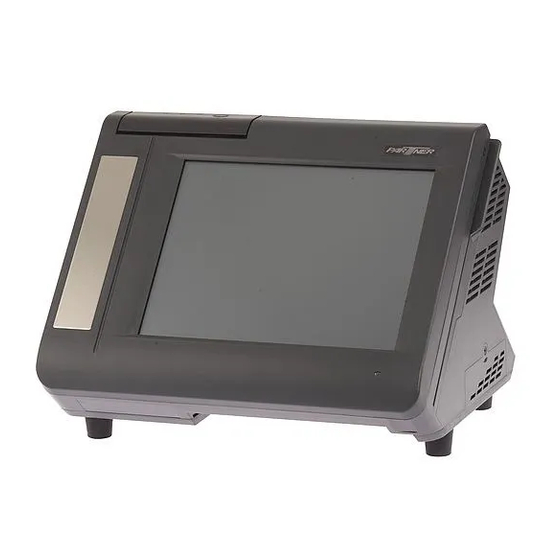
Identifying components This section describes the parts and connectors on the machine. Front-right view Figure 1.2 Front-right view Component Description Power Button 10.4-inch TFT LCD; 5-wire Resistive touch IO Panel LED Power Indicator Tripple-track MSR... -
Page 10: Rear View
Rear view Figure 1.3 Rear view Component Description 2x20 VFD customer display 80mm thermal receipt printer with cutter and control board Printer paper exit Roller gear door Printer cover handle Feed button C H A P T E R 1 G E T T I N G S T A R T E D... - Page 11 I/O connectors Figure 1.4 I/O connectors Connector Description COM4 port COM3 port COM2 port LAN port (RJ-45) PS/2 keyboard port 12V power connector RJ-11 cash drawer port VGA port COM1 port USB ports...
-
Page 12: Connecting Peripheral Devices
Connecting peripheral devices Peripheral devices such as a printer or scanner can be connected to the machine. Refer to the user manual of the device you are connecting for instructions on installing drivers where needed. MR HS AA CD SD RD TR ADSL modem or router Adapter Keyboard... -
Page 13: Connecting A Cash Drawer
Connecting a cash drawer Refer to the following to connect a cash drawer. The cash drawer RJ-11 connector is DC+24V. Ensure the cash drawer to be connected matches this power specification. IMPORTANT 1. Locate the I/O panel that is at the bottom of the machine. -
Page 14: Powering The Machine On And Off
Powering the machine on and off Refer to the following to power on and off the machine. 1. Locate the I/O panel that is at the bottom of the machine. 2. Connect the adapter to the power cable, and then insert the power plug into an electrical outlet (AC100 - 240 V). -
Page 15: Installing The Thermal Paper Roll
Installing the thermal paper roll Refer to the following to install the thermal paper roll. 1. Open the printer cover. 2. Insert the thermal paper roll as shown on the picture. 3. Pull a portion of the paper over the printer output part. -
Page 16: Using The Feed Button
Using the feed button Figure 1.8 The feed button Refer to the following to use the feed button. • Press the feed button once and one line paper is fed. • Hold on to the feed button and it keeps feeding paper. It will stop when you release it. • Hold on to the feed button before you power up the system. -
Page 17: Clearing A Thermal Printer Paper Jam
Clearing a thermal printer paper jam To clear a thermal printer paper jam 1. Remove the small cover from the top case of the thermal printer. 2. Try rotating the roller gear manu- ally to free the paper. - Page 18 C H A P T E R 1 G E T T I N G S T A R T E D...
-
Page 19: Chapter 2 Bios Setup
CHAPTER 2 BIOS SETUP The primary function of the BIOS (Basic Input and Output System) is to identify and initiate component hardware. The BIOS parameters are stored in non-volatile BIOS memory (CMOS). CMOS contents don’t get erased when the computer is turned off. The following topics are described in this chapter. • About the Setup Utility on page 13 • Standard CMOS features on page 16 • Advanced BIOS Features on page 18... -
Page 20: Entering The Setup Utility
Entering the Setup Utility When you power on the system, BIOS enters the Power-On Self Test (POST) routines. POST is a series of built-in diagnostics performed by the BIOS. After the POST routines are completed, the following message appears: Press DEL to enter SETUP Press the delete key <Delete>... -
Page 21: Using Bios
Using BIOS When you start the Setup Utility, the main menu appears. The main menu of the Setup Utility displays a list of the options that are available. A highlight indicates which option is currently selected. Use the cursor arrow keys to move the highlight to other options. -
Page 22: Standard Cmos Features
Standard CMOS features Selecting Standard CMOS Features on the main menu displays the following menu: Phoenix - AwardBIOS CMOS Setup Utility Standard CMOS Features Date (mm:dd:yy) Mon, Jul 6 2010 Item Help Time (hh:mm:ss) 8 : 33 : 14 ► IDE Channel 0 Master [ None] ►... - Page 23 IDE Channel 0/1 Master/Slave This field is used to configure the IDE hard drive installed in the system. Move the cursor to highlight the IDE Primary/Secondary Master/Slave fields and press <Enter>. The IDE Primary Master submenu opens: Phoenix - AwardBIOS CMOS Setup Utility IDE Channel 0 Master IDE HDD Auto-Detection [Press Enter] Item Help IDE Channel 0 Master [Auto] Access Mode [Auto] Capacity 80 GB Cylinder 38309 Figure 2.3 IDE Primary Head Master submenu Precomp...
-
Page 24: Advanced Bios Features
Advanced BIOS Features Selecting Advanced BIOS Features on the main menu opens up this screen: Phoenix - AwardBIOS CMOS Setup Utility Advanced BIOS Features ► Hard Disk Boot Priority [Press Enter] Item Help ► Network Boot Priority [Press Enter] First Boot Device [USB-ZIP] Second Boot Device [USB-CDROM]... -
Page 25: Hard Disk Boot Priority
Hard Disk Boot Priority Selecting Hard Disk Boot Priority opens up this screen. Phoenix - AwardBIOS CMOS Setup Utility Hard Disk Boot Priority Ch0 M. : ST380815AS Item Help 2. Bootable Add-in Cards Figure 2.5 Hard Disk Boot Priority menu ↑↓→←:Move Enter:Select +/-/PU/PD:Value F10:Save ESC:Exit F1:General Help F5:Previous Values F6:Fail-Safe Defaults... -
Page 26: Network Boot Priority
Network Boot Priority Selecting Network Boot Priority opens up this screen. Phoenix - AwardBIOS CMOS Setup Utility Network Boot Priority Legacy Lan Card Item Help Figure 2.6 Network Boot Priority menu ↑↓→←:Move Enter:Select +/-/PU/PD:Value F10:Save ESC:Exit F1:General Help F5:Previous Values F6:Fail-Safe Defaults F7:Optimized Defaults Network Boot Priority... -
Page 27: Advanced Chipset Features
Advanced Chipset Features This option displays critical timing parameters of the mainboard. Leave the items on this menu at their default settings unless you are very familiar with the technical specifications of the system hardware. If you change the values incorrectly, you may introduce fatal errors or recurring instability into the system. Phoenix - AwardBIOS CMOS Setup Utility Advanced Chipset Features DRAM Timing Selectable [By SPD]... -
Page 28: Pci Express Boot Port Func
► PCI Express Boot Port Func Use this item to control the PCI-E ports on the mainboard. Select the item and press <Enter> to open the following menu: Phoenix - AwardBIOS CMOS Setup Utility PCI Express Root Port Func PCI Express Port 1 [Auto] Item Help PCI Express Port 2... -
Page 29: Integrated Peripherals
Integrated Peripherals This option defines the operation of peripheral components on the system’s input/output ports. Phoenix - AwardBIOS CMOS Setup Utility Integrated Peripherals ► OnChip IDE Device [Press Enter] Item Help ► SuperIO Device [Press Enter] Onboard Lan Boot ROM [Disabled] Com1 With Voltage [None] Com2 With Voltage [None] Com3 With Voltage [None] Com4 With Voltage [None]... -
Page 30: Onchip Ide Device
► OnChip IDE Device Use this item to enable or disable the PCI IDE channels that are integrated on the mainboard. Select the item and press <Enter> to open the following menu: Phoenix - AwardBIOS CMOS Setup Utility OnChip IDE Device IDE HDD Block Mode [Enabled] Item Help... - Page 31 *** On-Chip Serial ATA Setting *** The following items allow you to configure the settings about On-Chip Serial ATA. On-Chip Serial ATA This feature allows users to select the SATA function modes. Setting at Disabled will disable SATA controller. Set at Auto will allow the BIOS to arrange it. Setting Combined Mode will make PATA and SATA combined. Max.
-
Page 32: Superio Device
► SuperIO Device Use this item to change settings for I/O devices. Select the item and press <Enter> to open the following menu: Phoenix - AwardBIOS CMOS Setup Utility SuperIO Device Onboard Serial Port 1 [3F8/IRQ4] Item Help Onboard Serial Port 2 [2F8/IRQ3] PWRON After PWR-Fail [Off]... -
Page 33: Usb Device Setting
► USB Device Setting Use this item to change settings for USB devices. Select the item and press <Enter> to open the following menu: Phoenix - AwardBIOS CMOS Setup Utility USB Device Setting USB 1.0 Controller [Enabled] Item Help USB 2.0 Controller [Enabled] USB Operation Mode [High Speed]... -
Page 34: Power Management Setup
Power Management Setup Use these items to control system power management. Modern operating systems take care of much of the power management. This mainboard supports ACPI (Advanced Configuration and Power Interface). Phoenix - AwardBIOS CMOS Setup Utility Power Management Setup Soft-Off by PWR-BTTN [Instant-Off] Item Help ** Reload Global Timer Events ** Figure 2.13 Power Management Setup menu ↑↓→←:Move Enter:Select +/-/PU/PD:Value F10:Save ESC:Exit F1:General Help... -
Page 35: Pnp/Pci Configurations
PnP/PCI Configurations This option configures how PnP (Plug and Play) and PCI expansion cards operate in the system. Both the ISA and PCI buses on the mainboard use system IRQs (Interrupt ReQuests) and DMAs (Direct Memory Access). You must set up the IRQ and DMA assignments correctly through the PnP/PCI Configurations menu; otherwise, the mainboard will not work properly. Selecting “PnP/PCI Configurations” on the main menu displays this menu: Phoenix - AwardBIOS CMOS Setup Utility PnP/PCI Configurations Reset Configuration Data [Disabled] Item Help ► IRQ Resources [Press Enter] INT Pin 1 Assignment Auto... -
Page 36: Irq Resources
► IRQ Resources This menu can only be accessed when the Resources Controlled by menu is set to Manual. In the IRQ Resources sub-menu, if you change any of the IRQ assignations to Legacy ISA, then that Interrupt Request Line is reserved for a legacy ISA expansion card. Press <Esc> to close the IRQ Resources sub-menu. Phoenix - AwardBIOS CMOS Setup Utility IRQ Resources IRQ-3 assigned to... -
Page 37: Pc Health Status
PC Health Status On mainboards that support hardware monitoring, this item lets you monitor the parameters for critical voltages, and critical temperatures. Several fields are for information only and are not configurable. Phoenix - AwardBIOS CMOS Setup Utility PC Health Status CPU Warning Temperature [Disabled] Item Help Current System Temp. 32ºC/ 89ºF Current CPU1 Temperature 46ºC/ 114ºF Current CPUFAN Speed 5625 RPM... -
Page 38: Frequency/Voltage Control
Frequency/Voltage Control Use these items to control system frequency and voltage. Phoenix - AwardBIOS CMOS Setup Utility Frequency/Voltage Control Spread Spectrum [Enabled] Item Help Figure 2.17 Frequency/ Voltage Control menu ↑↓→←:Move Enter:Select +/-/PU/PD:Value F10:Save ESC:Exit F1:General Help F5:Previous Values F6:Fail-Safe Defaults F7:Optimized Defaults Spread Spectrum When the motherboard clock generator pulses, the extreme values (spikes) of the pulses creates EMI... -
Page 39: Other Bios Options
Other BIOS Options This section covers the other options that are available from the main menu: Phoenix - AwardBIOS CMOS Setup Utility ► Standard CMOS Feature ► Frequency/Voltage Control ► Advanced BIOS Features Load Fail-Safe Defaults ► Advanced Chipset features Load Optimized Defaults ►... -
Page 40: Exit Without Saving
Set Supervisor and User Passwords These items can be used to install a password. A Supervisor password takes precedence over a User password, and the Supervisor can limit the activities of a User. To install a password, follow these steps: 1. -
Page 41: Chapter 3 Upgrading Components
CHAPTER 3 UPGRADING COMPONENTS This chapter describes how to upgrade components for the PT-6210-E. The following topics are described. • Safety and precautions on page 35 • Before you begin on page 36 • Upgrading the hard drive on page 37 Safety and precautions Computer components and electronic circuit boards can be damaged by discharges of static electricity. -
Page 42: Before You Begin
Before you begin Make sure you have a stable, clean working environment. Dust and dirt can get into components and may cause mal-function. Adequate lighting and proper tools can prevent you from accidentally damaging the internal components. Most of the electrical and mechanical connections can be disconnected by using your fingers. It is recommended that you do not use needle-nosed pliers to disconnect connectors as these can damage the soft metal or plastic parts of the connectors. -
Page 43: Upgrading The Hard Drive
Upgrading the hard drive Refer to the following to remove and replace the hard drive. 1. Turn off the machine properly through the operating system. 2. Disconnect the power cord from the power outlet. 3. Remove the one screw 4. Pull out the hard drive tray. 5. - Page 44 C H A P T E R 3 U P G R A D I N G C O M P O N E N T S...
-
Page 45: Appendix
If failure is detected in an area other than the mainboard (such as the keyboard or an adapter card), an error message is displayed on the screen and testing is stopped. If your system does not successfully complete the POST, but displays a blank screen, have the PT-6210-E serviced. -
Page 46: Beep Message Errors At Post
Replace the battery. FAILED The battery may be weak. Replace the battery. CMOS CHECKSUM ERROR The CMOS may be corrupt. Have the PT-6210-E serviced. HARD DISK(S) FAIL (80) HDD reset failed. Have the PT-6210-E serviced. HDD controller diagnostics HARD DISK(S) FAIL (40) Have the PT-6210-E serviced. -
Page 47: General Problems
Refer to the following general problems you may encounter. PROBLEM SOLUTION The display screen is dark. Make sure that the PT-6210-E is not in suspend mode. An incorrect date and time are displayed. Correct the date and time using the DOS DATE and TIME commands or the options in the Setup Utility. (You can also set the date and time in... -
Page 48: Having The Pt-6210-E Serviced
Having the PT-6210-E Serviced If you are unable to solve the problem, you should have the terminal serviced. Pack the terminal in the original carton. (See “Unpacking the PT-6210-E” on page 1.) Include a description of the problem and a checklist of the steps you took when trying to fix the problem. The information may be useful to the service personnel. Return the terminal to the place you purchased it. A P P E N D I X... -
Page 49: Specifications
Specifications Intel Atom N270 @ 1.6GHz/512K L2 cache Chipset Intel 945GSE + ICH7M Memory System ships with DDR2 1GB std, support up to 2GB 10.4” TFT-LCD Resolution 1024x768 Touch 5-wire Resistive touch LCD brightness 250 nit (w/o touch) 10/100/1000Mbps onboard Ethernet controller Storage SATA 3.5” hard drive or optional SATA SSD 4 * COM ports... -
Page 50: Paper Type
Paper type Thermal roll paper (single sheet) Original paper No. P350 KSP Original paper No. TF50KS-E NIPPON PAPER INDUSTRIES CO., LTD. Original paper No. AF50KS-E JUJO THERMAL Certified paper Original paper No. PD150R OJI PAPER MFG. CO., LTD. Original paper No. PD160R OJI PAPER MFG. CO., LTD. Original paper No.
Need help?
Do you have a question about the PT-6210-E and is the answer not in the manual?
Questions and answers