Table of Contents
Advertisement
Advertisement
Table of Contents

Related Manuals for Partner PT-6212-EB


Summary of Contents for Partner PT-6212-EB
- Page 1 All in one POS Terminal PT-6212-EB Service Manual...
-
Page 3: Declaration Of Conformity
Copyright This publication, including all photographs, illustrations and software, is protected under international copyright laws, with all rights reserved. Neither this manual, nor any of the material contained herein, may be reproduced without written consent of the author. Disclaimer The information in this document is subject to change without notice. The manufacturer makes no representa- tions or warranties with respect to the contents hereof and specifically disclaims any implied warranties of merchantability or fitness for any particular purpose. -
Page 4: About This Manual
About this manual The service manual provides service information for the PT-6212-EB. This manual is designed to help train service personnel to locate and fix failing parts on the machine. This manual consists of the following sections: Chapter 1 Getting Started: This section covers unpacking and checking the package contents, and identifying components. -
Page 5: Table Of Contents
TABLE OF CONTENTS CHAPTER 1 GETTING STARTED ..........1 Unpacking the machine .................1 Identifying components .................2 Connector pin define ..................5 CHAPTER 2 BIOS SETUP ............9 About the Setup Utility ...................9 Entering the Setup Utility ................10 BIOS navigation keys ................10 Using BIOS .....................11 Main Screen ....................12 Advanced Settings ..................13... - Page 6 Hard drive.....................60 Customer Display ..................61 Speaker ......................61 LCD Panel ....................62 Inverter ......................62 Memory ......................63 Battery ......................63 APPENDIX PART LIST AND SPECIFICATION ......65 Part list for PT-6212-EB main parts..............66 Part list for PT-6212-EB printer parts ............68 Specifications ....................69 Paper type ....................70...
- Page 7 Figure 1.1 Unpacking the machine ............... 1 Figure 1.2 Front-right view ................2 Figure 1.3 Rear view ..................3 Figure 1.4 PT-6212-EB I/O connectors ............4 Figure 2.1 Main BIOS screen ..............10 Figure 2.2 Main Screen ................12 Figure 2.3 Advanced Settings Screen ............13 Figure 2.4 IDE Configuration sub-menu............
-
Page 9: Chapter 1 Getting Started
CHAPTER 1 GETTING STARTED This chapter describes how to unpack and identifying components on the device. The following topics are described. • Unpacking the machine on page 1 • Identifying components on page 2 • Connector pin define on page 5 Unpacking the machine It is a good idea to save the packaging materials and shipping box in case that machine needs to be returned for service. -
Page 10: Identifying Components
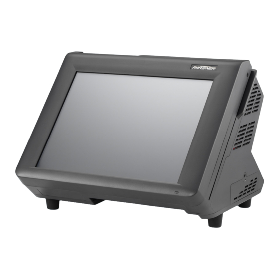
Identifying components This section describes the parts and connectors on the machine. Front-right view Figure 1.2 Front-right view Component Description Power Button 12.1-inch TFT LCD; 5-wire Resistive touch IO Panel LED Power Indicator Tripple-track MSR C H A P T E R 1 G E T T I N G S T A R T E D... -
Page 11: Figure 1.3 Rear View
Rear view Figure 1.3 Rear view Component Description 2x20 VFD customer display 80mm thermal receipt printer with cutter and control board Printer paper exit Roller gear door Printer cover handle Feed button... -
Page 12: Figure 1.4 Pt-6212-Eb I/O Connectors
I/O connectors Figure 1.4 PT-6212-EB I/O connectors Connector Description PS/2 keyboard port COM4 port LAN port (RJ-45) COM2 port COM3 port 12V power connector RJ-11 cash drawer port USB ports COM1 port VGA port C H A P T E R 1 G E T T I N G S T A R T E D... -
Page 13: Connector Pin Define
Connector pin define This section describes the connectors pin define. COM connector pin define Signal Signal SOUT VGA connector pin define Signal Signal Signal AGND Green AGND DDC DAT Blue AGND Horizontal Sync Vertical Sync DDC CLK USB connector pin define Signal USB Vcc USB -... - Page 14 RJ-11 Cash Drawer connector pin define Signal CASEOPEN2 CASH1 CASEOPEN1 CASH2 DC 12V input connector pin define Signal PS/2 connector pin define Signal Keyboard Data Keyboard Clock C H A P T E R 1 G E T T I N G S T A R T E D...
- Page 15 LAN connector pin define Signal Signal TXA+ TXC- TXA- TXB- TXB+ TXD+ TXC+ TXD- Parallel connector pin define Signal Signal Signal Strob# Acknowledge# Data 0 Busy Data 1 Paper Empty# Data 2 Printer Select Data 3 Auto Form Feed# Data 4 Error# Data 5 Initialize#...
- Page 16 DC 12V output connector pin define Signal +12V SATA connector pin define Signal Signal SATA_RX- SATA_TX+ SATA_RX+ SATA_TX- C H A P T E R 1 G E T T I N G S T A R T E D...
-
Page 17: Chapter 2 Bios Setup
CHAPTER 2 BIOS SETUP The primary function of the BIOS (Basic Input and Output System) is to identify and initiate component hardware. The BIOS parameters are stored in non-volatile BIOS memory (CMOS). CMOS contents don’t get erased when the computer is turned off. The following topics are described in this chapter. •... -
Page 18: Entering The Setup Utility
Entering the Setup Utility When you power on the system, BIOS enters the Power-On Self Test (POST) routines. POST is a series of built-in diagnostics performed by the BIOS. After the POST routines are completed, the following message appears: Press DEL to run Setup Press the delete key <Delete>... -
Page 19: Using Bios
Using BIOS When you start the Setup Utility, the main screen appears. The main screen of the Setup Utility displays a list of the options that are available. A highlight indicates which option is currently selected. Use the cursor arrow keys to move the highlight to other options. -
Page 20: Main Screen
Main Screen This screen includes System BIOS Information, Processor, System memory and displays the System Time and System Date. Figure 2.2 Main Screen System Overview This screen displays System BIOS Information, Processor, System memory, System Time and System Date. System Time/ System Date The System Time and System Date items show the current date and time held by the machine. -
Page 21: Advanced Settings
Advanced Settings This setup screen includes sub-menus for IDE Configuration, USB Configuration, ACPI Configurations, MPS Configurations, Super IO Configurations and Hardware Health Configuration. Figure 2.3 Advanced Settings Screen Spread Spectrum When the motherboard clock generator pulses, the extreme values (spikes) of the pulses creates EMI (Electromagnetic Interference). -
Page 22: Ide Configuration
IDE Configuration Figure 2.4 IDE Configuration sub-menu Hard Disk Write Protect This item will be effective only if the device is accessed through BIOS. C H A P T E R 2 B I O S S E T U P... -
Page 23: Primary/ Secondary Ide Master
Primary/ Secondary IDE Master Figure 2.5 Primary/ Secondary IDE Master sub-menu Type Select [Auto] to automatically detect hard disk drive. If auto detection is successful, the BIOS Setup automatically fills in the correct values for the remaining fields on this sub-menu. If the auto detection fails, it may due to that the hard disk is too old or too new. -
Page 24: Mps Configuration
MPS Configuration Figure 2.6 MPS Configuration sub-menu MPS Revision This item allows user to select the version of the Multi-Processor Specification (MPS). C H A P T E R 2 B I O S S E T U P... -
Page 25: Superio Configuration
SuperIO Configuration Figure 2.7 SuperIO Configuration sub-menu Parallel Port Address This item allows user to select the I/O address for the parallel port. Parallel Port Mode This item allows user to select the parallel port mode. EPP Version This item allows user to select the version of EPP. ECP Mode DMA Channel These items are used to assign the DMA channel for the ECP mode. -
Page 26: Hardware Health Configuration
Hardware Health Configuration Figure 2.8 Hardware Health Configuration sub- menu H/W Health Function This function is used to enable/ disable the Hardware Health Event Monitoring, that gives you an overview of the Temperature, fan speed and voltage information. Chassis Intrusion This function allows you to enable/ disable chassis intrusion, that can latch a chassis intrusion event even when the system is turned off, as long as battery or standby power is still present. -
Page 27: Acpi Configuration
ACPI Configuration Figure 2.9 ACPI Settings sub-menu Suspend mode Use this item to define how the system suspends. In the default, S1(POS), the suspend mode is equivalent to a software power down. If you select S3(STR), the suspend mode is a suspend to RAM - the system shuts down with the exception of a refresh current to the system memory. -
Page 28: Usb Configuration
USB Configuration Figure 2.10 USB Configuration sub-menu Legacy USB Support When enabled, the BIOS will enable legacy support for USB keyboards, mice and floppy drives. You will be able to use these USB devices even with operating systems that do not support USB. USB 2.0 Controller Mode This item is used to select the speed mode of USB 2.0 controller. -
Page 29: Boot Settings Configuration
Boot Settings Configuration This screen allow you to configure the boot options. Figure 2.11 Boot Settings screen Typematic Rate This item allows you to specify the typematic rate. -
Page 30: Boot Device Priority
Boot Device Priority Use this screen to specify the order in which the system checks for the device to boot from. Figure 2.12 Boot Device Priority sub-menu 1st Boot Device Set the boot device options to determine the sequence in which the computer checks which device to boot from. -
Page 31: Hard Disk Drives
Hard Disk Drives Use this screen to view the hard disk drives in the system. Figure 2.13 Hard Disk Drives sub-menu 1st Drive Use this item to view the hard disk drives in the system. -
Page 32: Boot Settings Configuration
Boot Settings Configuration Figure 2.14 Boot Settings Configuration sub-menu Quick Boot Enabling this setting will cause the BIOS power-on self test routine to skip some of its tests during booting for faster system boot. Bootup Num-Lock This setting is to set the Num Lock status when the system is powered on. Setting to [On] will turn on the Num Lock key when the system is powered on. -
Page 33: Chipset Settings
Chipset Settings This screen allow you to configure the North Bridge and South Bridge chipset options. Figure 2.15 Chipset Settings screen... -
Page 34: North Bridge Chipset Configuration
North Bridge Chipset Configuration Figure 2.16 North Bridge Chipset Configuration sub-menu DRAM Frequency This item specify the DRAM frequency of the system. Configure DRAM Timing By SPD Choose Enabled, will automatically configure the DRAM Timing depending on the “DRAM Frequency” selection. -
Page 35: South Bridge Chipset Configuration
South Bridge Chipset Configuration Figure 2.17 South Bridge Chipset Configuration sub-menu USB 2.0 Controller The USB 2.0 Controller item allows USB 2.0 functionality. Audio HDA Controller This item allows the High Definition Audio interface integrated in the Southbridge functionality. SMBUS Controller This item allows SMBUS controller to monitor the system temperature and voltage. -
Page 36: Security Settings
Security Settings This screen allows you to configure the system security settings. Figure 2.18 Security Settings screen Supervisor/ User Password Indicates whether a supervisor/ user password has been set. If the password has been installed, Installed displays. If not, Not Installed displays. Change Supervisor/ User Password These items can be used to install a password. -
Page 37: Exit Menu
Exit Menu This screen allows you to load the optimal or failsafe default values, and save or discard changes. Figure 2.19 Exit Menu screen Save Changes and Exit Highlight this item and press <Enter> to save the changes that you have made in the Setup Utility and exit the Setup Utility. -
Page 38: Load Failsafe Defaults
Load Failsafe Defaults This option opens a dialog box that lets you load fail-safe defaults for all appropriate items in the Setup Utility. The fail-safe defaults place no great demands on the system and are generally stable. If the system is not functioning correctly, try loading the fail-safe defaults as a first step in getting the system working properly again. -
Page 39: Chapter 3 Installing Drivers And Software
Use an external CD-ROM drive to install the drivers or copy the drivers to a USB flash drive and then plug to the machine. When you insert the CD ROM the following screen appears. Check PT-6212-EB that is listed under the “Install Terminal Drivers” and “Install Device Drivers” menus. -
Page 40: Intel Chipset Driver
The Intel Chipset Device Software updates the Windows INF files so that the Intel chipset is correctly configured. Follow these instructions to install the chipset software : 1. Browse to the \PT-6212-EB Driver\winxp\ folder. 2. Double-click Infinst.exe. The following screen appears. Click Next to continue. - Page 41 4. Browse the ReadMe Information, then click Next. 5. The Intel Chipset Software Utility files are installed to the system. When prompted to restart, select Yes, I want to restart my computer now. Then click Finish to restart the system.
-
Page 42: Intel Chipset Graphics Driver
Intel Chipset Graphics Driver Refer to the following to install the graphics drivers. 1. Browse to the \PT-6212-EB Driver\winxp\Graphics\ folder. 2. Double-click Setup.exe. The following screen appears. Read the release version, and then click Next. 3. Read the license agreement, then click Yes. - Page 43 4. Browse the ReadMe Information, then click Next. 5. When installation is completed, select Yes, I want to restart my computer now. Then click Finish to restart the system.
-
Page 44: Lan Driver
LAN Driver Refer to the following to install the LAN drivers. 1. Browse to the \PT-6212-EB Driver\winxp\Lan folder. 2. Double-click the setup.exe. The following screen appears. Click Next to continue. 3. Click Install to begin installation. C H A P T E R 3 I N S T A L L I N G D R I V E R S A N D S O F T W A R E... - Page 45 4. When installation is completed, click Finish.
-
Page 46: Audio Driver
Audio Driver Refer to the following to install the audio drivers. 1. Browse to the \PT-6212-EB Driver\winxp\Audio folder. 2. Double-click the Setup.exe. The following screen appears. Click Next to continue. 3. When installation is completed, select Yes, I want to restart my computer now. Then click Finish to restart the system. -
Page 47: Touch Screen Driver
Touch Screen Driver Refer to the following to install the touch screen driver. 1. Browse to the \PT-6212-EB Driver\winxp\eGalax Touch\All_In_One_2k_XP_Vista_5.6.0.6806\ folder. 2. Double-click setup.exe. The following screen appears. Click Next to continue. 3. Check the box for Install PS/2 interface drive and then click Next to continue. - Page 48 4. System will give you a warning, click Ok to continue. 5. Uncheck the box for Install RS232 interface drive and then click Next to continue. 6. Check the box for None and then click Next to continue. C H A P T E R 3 I N S T A L L I N G D R I V E R S A N D S O F T W A R E...
- Page 49 7. System will give you a warning, click Ok to continue. 8. Uncheck the box for Support Mulit-Monitor System and then click Next to continue. 9. Click Next to continue.
- Page 50 10. Click Next to continue. 11. Click Yes, I want to restart my computer now and then click Finish. C H A P T E R 3 I N S T A L L I N G D R I V E R S A N D S O F T W A R E...
-
Page 51: Calibrating The Touchscreen
Calibrating the touchscreen Follow these instructions to calibrate the touchscreen using the TouchKit application: 1. Launch the eGalaxTouch application from the Windows desktop by clicking on Start > Programs > eGalax Touch > Configure Utility. 2. Select the Tools page. 3. - Page 52 4. Use your finger to touch the blinking X Symbol on the screen until stop blinking. 5. Click OK to complete the 4 points calibration. You may also use this application to adjust the touch settings. NOTE C H A P T E R 3 I N S T A L L I N G D R I V E R S A N D S O F T W A R E...
-
Page 53: Chapter 4 Locating The Problem
CHAPTER 4 LOCATING THE PROBLEM Refer to this section to locate the problem with the machine. The following topics are described. • General checkout guidelines on the page 41 • Cash drawer checkout on the page 41 • LCD symptoms on the page 42 •... -
Page 54: Lcd Symptoms
Figure 4.1 Connecting a cash drawer Cashdrawer 2. Turn on the machine . Refer to the following to prevent incorrect cash drawer status detection by the system: Port I/O Port Address Condition Note Cashdrawer A High(1) → Close If Bit is set to Low to open the Control port cash drawer, after it must be set Low(0) →... -
Page 55: Touch Screen Symptoms
Touch screen symptoms Symptom Corrective Procedure • Touchscreen does not 1. Install and run the touchscreen calibration program from the driver function • No virtual mouse 2. Reseat the panel cable. • Cursor doesn’t follow when 3. Reseat the touchscreen board-to-touch panel cable. touching the screen 4. -
Page 56: Usb Symptoms
USB symptoms Symptom Corrective Procedure • USB device does not function 1. Check that the USB device is detected in Windows Device Manager. 2. Reinstall the USB device driver. 3. Replace the mainboard. Peripheral-device symptoms Symptom Corrective Procedure • USB ports do not work 1. -
Page 57: Mainboard Jumper
Mainboard jumper JLV2 JLV1 JCMOS Figure 4.2 PT-6212-EB mainboard jumper Jumper Setting Description 1-2 closed (default) Normal JCMOS 2-3 closed Clear CMOS 1-2 closed 3-4 closed (default) (COM3) 5-6 closed 1-2 closed 3-4 closed (default) (COM4) 5-6 closed... -
Page 58: Mainboard Connectors
PS/2 port parallel port COM port Figure 4.3 PT-6212-EB mainboard connectors C H A P T E R 4 L O C A T I N G T H E P R O B L E M... -
Page 59: Thermal Printer Control Board Connectors
Thermal printer control board connectors connector to mainboard connector to thermal printer Figure 4.5 Thermal printer control board connectors Inverter connectors connector to mainboard connector to connector to Figure 4.4 Inverter connectors... - Page 60 C H A P T E R 4 L O C A T I N G T H E P R O B L E M...
-
Page 61: Chapter 5 Replacing Field Replaceable Units (Frus)
After replacing optional devices, make sure all screws, springs, or other small parts are in place and are not left loose inside the case. Metallic parts or metal flakes can cause electrical shorts. Only qualified personnel should perform repairs on the PT-6212-EB. Damage due to unauthorized servicing is not covered by the warranty. -
Page 62: Before You Begin
CAUTION Before you begin Make sure you have a stable, clean working environment. Dust and dirt can get into the PT-6212-EB com- ponents and may cause malfunction. Adequate lighting and proper tools can prevent you from accidentally damaging the internal components. Most of the electrical and mechanical connections can be disconnected by using your fingers. -
Page 63: Front Panel
Front Panel 1. Remove the two screws. 2. Open the front panel. Before proceeding, remove the following FRUs. • “Front Panel” on page 55. 1. Disconnect the cables. 2. Remove the screw. 3. Slide up and remove the MSR. -
Page 64: Thermal Printer
Thermal Printer 1. Open the printer cover. 2. Find the screw in the center of the printer. 3. Remove the screw. 4. Disconnect the cables. 5. Remove the printer. C H A P T E R 5 R E P L A C I N G F I E L D R E P L A C E A B L E U N I T S ( F R U s ) -
Page 65: Heatsink
Heatsink Before proceeding, remove the following FRUs. • “Front Panel” on page 55. 1. Remove the two screws from the heatsink bracket. 2. Remove the other two screws from the heatsink bracket. 3. Remove the heatsink bracket set. 4. Remove the six screws from the heatsink. -
Page 66: Thermal Printer Control Board
5. Remove the heatsink. CAUTION To avoid the heat sink clearance issue. When you replace the heat sink, check the thermal pads should be stuck between the contact surface of Thermal pads the heat sink and chips. Thermal printer control board Before proceeding, remove the following FRUs. -
Page 67: Mainboard
Mainboard Before proceeding, remove the following FRUs. • “Front Panel” on page 55. • “Heatsink” on page 57. 1. Disconnect the cables on the mainboard. 2. Remove the three screws from the mainboard tray. 3. Remove the mainboard tray. 4. Remove the screws from the mainboard I/O panel. -
Page 68: Hard Drive
Hard drive 1. Remove the screw. 2. Pull out the hard drive tray. 3. Disconnect the power cable and data cable from the hard drive. 4. Remove the four screws, then remove the hard drive out from the tray. C H A P T E R 5 R E P L A C I N G F I E L D R E P L A C E A B L E U N I T S ( F R U s ) -
Page 69: Customer Display
Customer Display 1. Remove the screw. 2. Disconnect the cables from the mainboard. 3. Slide out the customer display. Speaker Before proceeding, remove the following FRUs. • “Front Panel” on page 55. • “Heatsink” on page 57. • “Mainboard” on page 59. 1. -
Page 70: Lcd Panel
LCD Panel Before proceeding, remove the following FRUs. • “Front Panel” on page 1. Disconnect the cable on the mainboard. 2. Remove the screws from the LCD back cover. 3. Remove the back cover. 4. Disconnect the cable from the inverter. 5. -
Page 71: Memory
Memory Before proceeding, remove the following FRUs. • “Front Panel” on page 55. 1. Open the clips. 2. Pull out the memory module. Battery Before proceeding, remove the following FRUs. • “Front Panel” on page 55. 1. Open the hock. 2. - Page 72 C H A P T E R 5 R E P L A C I N G F I E L D R E P L A C E A B L E U N I T S ( F R U s )
-
Page 73: Appendix Part List And Specification
APPENDIX PART LIST AND SPECIFICATION Figure 6.1 Exploded diagram main parts... -
Page 74: Part List For Pt-6212-Eb Main Parts
Part list for PT-6212-EB main parts DESCRIPTION ITEM NO DESCRIPTION ITEM NO Front Bezel 25000500H1306 Speaker Bracket 21004500H602E Touch panel 2619040100006 Speaker 1370800000003 Heatsink Module LCD Panel 2614551121003 6605500H39000 Heatsink Bracket LCD Bracket 21004500H1013 21004500H2015 Heatsink Bracket Inverter 2614571121001 21004500H2011... -
Page 75: Figure 6.2 Exploded Diagram Printer Parts
Figure 6.2 Exploded diagram printer parts... -
Page 76: Part List For Pt-6212-Eb Printer Parts
Part list for PT-6212-EB printer parts DESCRIPTION ITEM NO Print Top 25000500H2302 Top Bracket 21004500H2005 Print Cover 25000500H2301 Feed Button 25003500H1303 Feed Button Base 25003500H1304 Feed Button PCB 700500H601015 Cut Cover 25003500H2302 Thermal Printer 2108010000105 Printer Base 25002500H2303 Control Board... -
Page 77: Specifications
Specifications Item PT-6212-EB-181S PT-6212-EB-182D Intel® Atom™ processor D425 (512K Intel® Atom™ processor D525 (1M CPU Type L2 Cache, 1.80 GHz, single core ) L2 Cache, 1.80 GHz, dual core ) 12” TFT color LCD, resolution 1024 x 768 Touch 5-wire Resistive touch... -
Page 78: Paper Type
Paper type Thermal roll paper (single sheet) Original paper No. P350 KSP Original paper No. TF50KS-E NIPPON PAPER INDUSTRIES CO., LTD. Original paper No. AF50KS-E JUJO THERMAL Certified paper Original paper No. PD150R OJI PAPER MFG. CO., LTD. Original paper No. PD160R OJI PAPER MFG. CO., LTD. Original paper No.
Need help?
Do you have a question about the PT-6212-EB and is the answer not in the manual?
Questions and answers