Table of Contents
Advertisement
Advertisement
Table of Contents

Subscribe to Our Youtube Channel
Related Manuals for Partner SP-1000-BZ


Summary of Contents for Partner SP-1000-BZ
- Page 1 POS Terminal SP-1000-BZ User Manual...
-
Page 3: Declaration Of Conformity
Copyright This publication, including all photographs, illustrations and software, is protected under international copyright laws, with all rights reserved. Neither this manual, nor any of the material contained herein, may be reproduced without written consent of the author. Disclaimer The information in this document is subject to change without notice. The manufacturer makes no representations or warranties with respect to the contents hereof and specifically disclaims any implied warranties of merchantability or fitness for any particular purpose. -
Page 4: About This Manual
SP-1000-BZ serviced, and technical specifications. Safety information Before installing and using the SP-1000-BZ, take note of the following precautions: • Read all instructions carefully. • Do not place the unit on an unstable surface, cart, or stand. -
Page 5: Table Of Contents
Identifying components .................3 Connecting peripheral devices ...............6 Connecting a cash drawer ................7 Powering the machine on and off ..............8 Mounting the SP-1000-BZ on the wall ............9 CHAPTER 2 BIOS SETUP ............11 About the Setup Utility .................11 Entering the Setup Utility ................12 BIOS navigation keys ................12... - Page 6 Before you begin ..................36 Upgrading the hard drive................37 APPENDIX .................. 39 Troubleshooting ...................39 Tips for Troubleshooting ................39 The Power-On Self Test ................39 Beep Errors at POST ...................39 Beep Message Errors at POST ..............40 General Problems ..................41 Having the SP-1000-BZ Serviced ...............42 Specifications ....................43...
-
Page 7: Chapter 1 Getting Started
CHAPTER 1 GETTING STARTED This chapter describes the procedures from unpacking the SP-1000-BZ, to powering it on. The following topics are described. • Unpacking the machine on page 1 • Checking the package contents on page 2 • Identifying components on page 3 • Connecting peripheral devices on page 6... -
Page 8: Checking The Package Contents
Checking the package contents After you unpack the device check that the following items are included. Driver CD with drivers and the user manual PDF file. SP-1000-BZ Adapter Power Cable If any item is missing or appears damaged, contact your dealer immediately. -
Page 9: Identifying Components
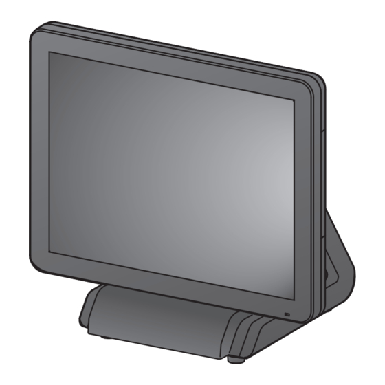
Identifying components This section describes the parts and connectors on the machine. Front-right view Figure 1.2 Front-right view Component Description 15-inch TFT LCD LED Power Indicator IO Panel HDD/ Adapter Compartment Power Button... -
Page 10: Rear View
Rear view Figure 1.3 Rear view Component Description MSR (optional) Slot HDD Compartment (for wall mounting) VFD Customer Display (optional) Slot Cable Compartment Do not block the air vents. No obstructions in 5 cm from the vents. CAUTION C H A P T E R 1 G E T T I N G S T A R T E D... - Page 11 I/O connectors Figure 1.4 SP-1000-BZ I/O connectors Connector Description COM 4 port VGA port COM 1 port USB ports RJ11 cash drawer port DC 12V input connector DC 12V output connector (for PM-116) Microphone jack Audio output jack COM 3 port...
-
Page 12: Connecting Peripheral Devices
Connecting peripheral devices Peripheral devices such as a printer or scanner can be connected to the machine. Refer to the user manual of the device you are connecting for instructions on installing drivers where needed. Adapter USB Compliant devices Cashdrawer PM-116 Monitor MR HS AA CD... -
Page 13: Connecting A Cash Drawer
Connecting a cash drawer Refer to the following to connect a cash drawer. The cash drawer RJ-11 connector is DC+24V. Ensure the cash drawer to be connected matches this power specification. IMPORTANT 1. Flip up the LCD panel, you can find the I/O panel is at the bottom of the LCD panel. -
Page 14: Powering The Machine On And Off
1. Locate the I/O panel that is at the bottom of the machine. 2. Connect the power cable to the DC- IN connector located on the right side of the SP-1000-BZ I/O panel. 3. Plug the power cable into an electrical outlet. Using adap- tor higher than 12V/7.5A may... -
Page 15: Mounting The Sp-1000-Bz On The Wall
Mounting the SP-1000-BZ on the wall The SP-1000-BZ can be attached to a wall mount (optional). 1. Turn off the power, and disconnect all power and peripheral cables. 2. Flip up the LCD panel. 3. Remove the screw that secure the base to the SP-1000-BZ. - Page 16 7. Align the mounting holes in the back of the SP-1000-BZ with the hooks on the wall mount bracket. 8. Insert the hooks on the wall mount bracket into the mounting holes in...
-
Page 17: Chapter 2 Bios Setup
CHAPTER 2 BIOS SETUP The primary function of the BIOS (Basic Input and Output System) is to identify and initiate component hardware. The BIOS parameters are stored in non-volatile BIOS memory (CMOS). CMOS contents don’t get erased when the computer is turned off. The following topics are described in this chapter. • About the Setup Utility on page 11 • Main Screen on page 14 • Advanced Settings on page 15... -
Page 18: Entering The Setup Utility
Entering the Setup Utility When you power on the system, BIOS enters the Power-On Self Test (POST) routines. POST is a series of built-in diagnostics performed by the BIOS. After the POST routines are completed, the following message appears: Press DEL to run Setup Press the delete key <Delete>... -
Page 19: Using Bios
Using BIOS When you start the Setup Utility, the main screen appears. The main screen of the Setup Utility displays a list of the options that are available. A highlight indicates which option is currently selected. Use the cursor arrow keys to move the highlight to other options. -
Page 20: Main Screen
Main Screen This screen includes System BIOS Information, Processor, System memory and displays the System Time and System Date. Figure 2.2 Main Screen System Overview This screen displays System BIOS Information, Processor, System memory, System Time and System Date. System Time/ System Date The System Time and System Date items show the current date and time held by the machine. -
Page 21: Advanced Settings
Advanced Settings This setup screen includes sub-menus for IDE Configuration, USB Configuration, ACPI Configurations, MPS Configurations, Super IO Configurations and Hardware Health Configuration. Figure 2.3 Advanced Settings Screen Spread Spectrum When the motherboard clock generator pulses, the extreme values (spikes) of the pulses creates EMI (Electromagnetic Interference). The Spread Spectrum function reduces the EMI generated by modulating the pulses so that the spikes of the pulses are reduced to flatter curves. If you do not have any EMI problem, leave the setting at Disabled for optimal system stability and performance. -
Page 22: Ide Configuration
IDE Configuration Figure 2.4 IDE Configuration sub-menu Hard Disk Write Protect This item will be effective only if the device is accessed through BIOS. C H A P T E R 2 B I O S S E T U P... -
Page 23: Primary/ Secondary Ide Master
Primary/ Secondary IDE Master Figure 2.5 Primary/ Secondary IDE Master sub-menu Type Select [Auto] to automatically detect hard disk drive. If auto detection is successful, the BIOS Setup automatically fills in the correct values for the remaining fields on this sub-menu. If the auto detection fails, it may due to that the hard disk is too old or too new. If the hard disk was already formatted on an older system, the BIOS Setup may detect incorrect parameters. -
Page 24: Cpu Configuration
CPU Configuration Figure 2.6 CPU Configuration sub-menu Max CPUID Value Limit When enabled, the processor will limit the maximum CPUID input value to 03h when queried, even if the processor supports a higher CPUID input value. When disabled, the processor will return the actual maximum CPUID input value of the processor when queried. -
Page 25: Mps Configuration
MPS Configuration Figure 2.7 MPS Configuration sub-menu MPS Revision This item allows user to select the version of the Multi-Processor Specification (MPS). -
Page 26: Superio Configuration
SuperIO Configuration Figure 2.8 SuperIO Configuration sub-menu Parallel Port Address This item allows user to select the I/O address for the parallel port. Parallel Port Mode This item allows user to select the parallel port mode. EPP Version This item allows user to select the version of EPP. ECP Mode DMA Channel These items are used to assign the DMA channel for the ECP mode. -
Page 27: Hardware Health Configuration
Hardware Health Configuration Figure 2.9 Hardware Health Configuration sub- menu H/W Health Function This function is used to enable/ disable the Hardware Health Event Monitoring, that gives you an overview of the Temperature, fan speed and voltage information. Chassis Intrusion This function allows you to enable/ disable chassis intrusion, that can latch a chassis intrusion event even when the system is turned off, as long as battery or standby power is still present. -
Page 28: Acpi Configuration
ACPI Configuration Figure 2.10 ACPI Settings sub-menu Suspend mode Use this item to define how the system suspends. In the default, S1(POS), the suspend mode is equivalent to a software power down. If you select S3(STR), the suspend mode is a suspend to RAM - the system shuts down with the exception of a refresh current to the system memory. ACPI APIC support This item allows user to enable or disable the APIC (Advanced Programmable Interrupt Controller) function. -
Page 29: Usb Configuration
USB Configuration Figure 2.11 USB Configuration sub-menu Legacy USB Support When enabled, the BIOS will enable legacy support for USB keyboards, mice and floppy drives. You will be able to use these USB devices even with operating systems that do not support USB. USB 2.0 Controller Mode This item is used to select the speed mode of USB 2.0 controller. BIOS EHCI Hand-Off This item allows you to enable support for operating systems without an EHCI hand-off feature. -
Page 30: Boot Settings Configuration
Boot Settings Configuration This screen allow you to configure the boot options. Figure 2.12 Boot Settings screen Typematic Rate This item allows you to specify the typematic rate. C H A P T E R 2 B I O S S E T U P... -
Page 31: Boot Device Priority
Boot Device Priority Use this screen to specify the order in which the system checks for the device to boot from. Figure 2.13 Boot Device Priority sub-menu 1st Boot Device Set the boot device options to determine the sequence in which the computer checks which device to boot from. -
Page 32: Hard Disk Drives
Hard Disk Drives Use this screen to view the hard disk drives in the system. Figure 2.14 Hard Disk Drives sub-menu 1st Drive Use this item to view the hard disk drives in the system. C H A P T E R 2 B I O S S E T U P... -
Page 33: Boot Settings Configuration
Boot Settings Configuration Figure 2.15 Boot Settings Configuration sub-menu Quick Boot Enabling this setting will cause the BIOS power-on self test routine to skip some of its tests during booting for faster system boot. Bootup Num-Lock This setting is to set the Num Lock status when the system is powered on. Setting to [On] will turn on the Num Lock key when the system is powered on. -
Page 34: Chipset Settings
Chipset Settings This screen allow you to configure the North Bridge and South Bridge chipset options. Figure 2.16 Chipset Settings screen C H A P T E R 2 B I O S S E T U P... -
Page 35: North Bridge Chipset Configuration
North Bridge Chipset Configuration Figure 2.17 North Bridge Chipset Configuration sub-menu DRAM Frequency This item specify the DRAM frequency of the system. Configure DRAM Timing By SPD Choose Enabled, will automatically configure the DRAM Timing depending on the “DRAM Frequency” selection. Choose Disabled, to customize the setup. Internal Graphics Mode Select This feature controls the amount of system memory that is allocated to the integrated graphic process when the system boot up. -
Page 36: South Bridge Chipset Configuration
South Bridge Chipset Configuration Figure 2.18 South Bridge Chipset Configuration sub-menu USB 2.0 Controller The USB 2.0 Controller item allows USB 2.0 functionality. Audio HDA Controller This item allows the High Definition Audio interface integrated in the Southbridge functionality. SMBUS Controller This item allows SMBUS controller to monitor the system temperature and voltage. Mini PCIE Port This item allows you to enable/ disable the Mini PCIe port. -
Page 37: Security Settings
Security Settings This screen allows you to configure the system security settings. Figure 2.19 Security Settings screen Supervisor/ User Password Indicates whether a supervisor/ user password has been set. If the password has been installed, Installed displays. If not, Not Installed displays. Change Supervisor/ User Password These items can be used to install a password. A Supervisor password takes precedence over a User password, and the Supervisor can limit the activities of a User. -
Page 38: Exit Menu
Exit Menu This screen allows you to load the optimal or failsafe default values, and save or discard changes. Figure 2.20 Exit Menu screen Save Changes and Exit Highlight this item and press <Enter> to save the changes that you have made in the Setup Utility and exit the Setup Utility. - Page 39 Load Failsafe Defaults This option opens a dialog box that lets you load fail-safe defaults for all appropriate items in the Setup Utility. The fail-safe defaults place no great demands on the system and are generally stable. If the system is not functioning correctly, try loading the fail-safe defaults as a first step in getting the system working properly again. If you only want to load fail-safe defaults for a specific option, select and display that option, and then press <F8>.
- Page 40 C H A P T E R 2 B I O S S E T U P...
-
Page 41: Chapter 3 Upgrading Components
CHAPTER 3 UPGRADING COMPONENTS This chapter describes how to upgrade components for the SP-1000-BZ. The following topics are described. • Safety and precautions on page 35 • Before you begin on page 36 • Upgrading the hard drive on page 37 Safety and precautions Computer components and electronic circuit boards can be damaged by discharges of static electricity. -
Page 42: Before You Begin
Before you begin Make sure you have a stable, clean working environment. Dust and dirt can get into components and may cause malfunction. Adequate lighting and proper tools can prevent you from accidentally damaging the internal components. Most of the electrical and mechanical connections can be disconnected by using your fingers. It is recommended that you do not use needle-nosed pliers to disconnect connectors as these can damage the soft metal or plastic parts of the connectors. -
Page 43: Upgrading The Hard Drive
Upgrading the hard drive Refer to the following to remove and replace the hard drive. 1. Turn off the device properly through the operating system. 2. Disconnect the power cord from the power outlet. 3. Remove the screw from the hard drive compartment cover. - Page 44 C H A P T E R 3 U P G R A D I N G C O M P O N E N T S...
-
Page 45: Appendix
If failure is detected in an area other than the mainboard (such as the keyboard or an adapter card), an error message is displayed on the screen and testing is stopped. If your system does not successfully complete the POST, but displays a blank screen, have the SP-1000-BZ serviced. -
Page 46: Beep Message Errors At Post
Replace the battery. FAILED The battery may be weak. Replace the battery. CMOS CHECKSUM ERROR The CMOS may be corrupt. Have the SP-1000-BZ serviced. HARD DISK(S) FAIL (80) HDD reset failed. Have the SP-1000-BZ serviced. HDD controller diagnostics HARD DISK(S) FAIL (40) Have the SP-1000-BZ serviced. -
Page 47: General Problems
Refer to the following general problems you may encounter. PROBLEM SOLUTION The display screen is dark. Make sure that the SP-1000-BZ is not in suspend mode. An incorrect date and time are displayed. Correct the date and time using the DOS DATE and TIME commands or the options in the Setup Utility. (You can also set the date and time in... -
Page 48: Having The Sp-1000-Bz Serviced
Having the SP-1000-BZ Serviced If you are unable to solve the problem, you should have the terminal serviced. Pack the terminal in the original carton. (See “Unpacking the SP-1000-BZ” on page 1.) Include a description of the problem and a checklist of the steps you took when trying to fix the problem. The information may be useful to the service personnel. -
Page 49: Specifications
Specifications Item SP-1000-BZ CPU Type Intel Atom™ processor D525 (1M L2 Cache, 1.80 GHz, dual core ) ® 15” Active TFT color LCD, resolution 1024 x 768 Touch 5-wire Resistive touch (PS2 interface) Memory 204pin DDR3 SO-DIMM 2GB (2 DIMM Sockets up to 4 GB) Ethernet IEEE 802.3 10/100/1000 BASE-T Gigabit Ethernet... - Page 50 3 tracks magnetic reader Optional Peripherals Customer display module (2 x 20 VFD) Operation Windows 7, Windows XP, Linux (ubuntu) , POSReady 2009, POSReady 7 System Power Supply AC100~240V/DC12V, 7.5A, 90 watt power adaptor Dimensions 360mm (W) x 240mm (D) x 360mm (H) Operating 0°C ~ +40°C Temp...
Need help?
Do you have a question about the SP-1000-BZ and is the answer not in the manual?
Questions and answers