Table of Contents
Advertisement
Advertisement
Table of Contents

Subscribe to Our Youtube Channel
Related Manuals for Partner PT-6212


Summary of Contents for Partner PT-6212
- Page 1 All in one POS Terminal PT-6212 Service Manual...
-
Page 3: Declaration Of Conformity
Copyright This publication, including all photographs, illustrations and software, is protected under international copyright laws, with all rights reserved. Neither this manual, nor any of the material contained herein, may be reproduced without written consent of the author. Disclaimer The information in this document is subject to change without notice. The manufacturer makes no representa- tions or warranties with respect to the contents hereof and specifically disclaims any implied warranties of merchantability or fitness for any particular purpose. -
Page 4: Safety Information
About this manual The service manual provides service information for the PT-6212. This manual is designed to help train service personnel to locate and fix failing parts on the machine. This manual consists of the following sections: Chapter 1 Getting Started: This section covers unpacking and checking the package contents, and identifying components. -
Page 5: Table Of Contents
TABLE OF CONTENTS CHAPTER 1 GETTING STARTED ..........1 Unpacking the machine .................1 Identifying components .................2 CHAPTER 2 BIOS SETUP ............5 About the Setup Utility ...................5 Entering the Setup Utility ................6 BIOS navigation keys ................6 Using BIOS ....................7 Standard CMOS features ................8 Advanced BIOS Features ................10 CPU Feature ....................12 Hard Disk Boot Priority .................13... - Page 6 MSR ......................53 Mainboard ....................54 Hard drive.....................55 Thermal Printer ....................56 Customer Display ..................57 Speaker ......................57 LCD Panel ....................58 Inverter ......................58 Touch Panel ....................59 Memory ......................59 Battery ......................59 APPENDIX PART LIST AND SPECIFICATION ......61 Part list for Charcoal PT-6212 ..............63 Specifications ....................64...
- Page 7 Figure 1.1 Unpacking the machine ............1 Figure 1.2 Front-right view ..............2 Figure 1.3 Rear view ................3 Figure 1.4 PT-6212 I/O connectors ............4 Figure 2.1 Main BIOS menu..............6 Figure 2.2 Standard CMOS Features menu ........... 8 Figure 2.3 IDE Primary Master submenu ..........
-
Page 9: Chapter 1 Getting Started
CHAPTER 1 GETTING STARTED This chapter describes how to unpack and identifying components on the device. The following topics are described. • Unpacking the machine on page • Identifying components on page Unpacking the machine It is a good idea to save the packaging materials and shipping box in case that machine needs to be returned for service. -
Page 10: Identifying Components
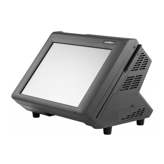
Identifying components This section describes the parts and connectors on the machine. Front-right view Figure 1.2 Front-right view Component Description Power Button 12.1-inch TFT LCD; 5-wire Resistive touch IO Panel LED Power Indicator Triple-track MSR C H A P T E R 1 G E T T I N G S T A R T E D... -
Page 11: Figure 1.3 Rear View
Rear view Figure 1.3 Rear view Component Description 2x20 VFD customer display Printer paper exit 80mm thermal receipt printer Printer button... -
Page 12: Figure 1.4 Pt-6212 I/O Connectors
I/O connectors Figure 1.4 PT-6212 I/O connectors Connector Description COM4 port COM3 port COM2 port LAN port (RJ-45) 12V power connector PS/2 keyboard port RJ-11 cash drawer port VGA port COM1 port USB ports C H A P T E R 1 G E T T I N G S T A R T E D... -
Page 13: Chapter 2 Bios Setup
CHAPTER 2 BIOS SETUP The primary function of the BIOS (Basic Input and Output System) is to identify and initiate component hardware. The BIOS parameters are stored in non-volatile BIOS memory (CMOS). CMOS contents don’t get erased when the computer is turned off. The following topics are described in this chapter. •... -
Page 14: Entering The Setup Utility
Entering the Setup Utility When you power on the system, BIOS enters the Power-On Self Test (POST) routines. POST is a series of built-in diagnostics performed by the BIOS. After the POST routines are completed, the following message appears: Press DEL to enter SETUP Press the delete key <Delete>... -
Page 15: Using Bios
Using BIOS When you start the Setup Utility, the main menu appears. The main menu of the Setup Utility displays a list of the options that are available. A highlight indicates which option is currently selected. Use the cursor arrow keys to move the highlight to other options. -
Page 16: Standard Cmos Features
Standard CMOS features Selecting Standard CMOS Features on the main menu displays the following menu: Phoenix - AwardBIOS CMOS Setup Utility Standard CMOS Features Date (mm:dd:yy) Mon, Jul 6 2009 Item Help Time (hh:mm:ss) 8 : 33 : 14 IDE Channel 0 Master [ None] ►... -
Page 17: Figure 2.3 Ide Primary Master Submenu
IDE Channel 0/2/3 Master/Slave This field is used to configure the IDE hard drive installed in the system. Move the cursor to highlight the IDE Primary/Secondary Master/Slave fields and press <Enter>. The IDE Primary Master submenu opens: Phoenix - AwardBIOS CMOS Setup Utility IDE Channel 0 Master IDE HDD Auto-Detection [Press Enter]... -
Page 18: Advanced Bios Features
Advanced BIOS Features Selecting Advanced BIOS Features on the main menu opens up this screen: Phoenix - AwardBIOS CMOS Setup Utility Advanced BIOS Features CPU Feature [Press Enter] Item Help ► Hard Disk Boot Priority [Press Enter] ► Virus Warning [Disabled] First Boot Device [USB-ZIP]... - Page 19 APIC Mode This item is used to activate the ACPI (Advanced Configuration and Power Management Interface) Mode. ACPI is a power management specification that makes hardware sta- tus information available to the operating system. ACPI enables a PC to turn its peripherals on and off for improved power management. It also allows the PC to be turned on and off by external devices, so that IMPORTANT mouse or keyboard activity wakes up the machine.
-
Page 20: Cpu Feature
CPU Feature Selecting CPU Feature opens up this screen. Phoenix - AwardBIOS CMOS Setup Utility CPU Feature Delay Prior to Thermal [16 Min] Item Help Thermal Management Thermal Monitor 1 Execute Disable Bit [Enabled] Figure 2.5 CPU Feature submenu ↑↓→←:Move Enter:Select +/-/PU/PD:Value F10:Save ESC:Exit F1:General Help F5:Previous Values F6:Fail-Safe Defaults F7:Optimized Defaults... -
Page 21: Hard Disk Boot Priority
Hard Disk Boot Priority Selecting Hard Disk Boot Priority opens up this screen. Phoenix - AwardBIOS CMOS Setup Utility Hard Disk Boot Priority Ch2 M. : ST380815AS Item Help 2. Bootable Add-in Cards Figure 2.6 Hard Disk Boot Priority menu ↑↓→←:Move Enter:Select +/-/PU/PD:Value F10:Save ESC:Exit F1:General Help F5:Previous Values F6:Fail-Safe Defaults... -
Page 22: Advanced Chipset Features
Advanced Chipset Features This option displays critical timing parameters of the mainboard. Leave the items on this menu at their default settings unless you are very familiar with the technical specifications of the system hardware. If you change the values incorrectly, you may introduce fatal errors or recurring instability into the system. Phoenix - AwardBIOS CMOS Setup Utility Advanced Chipset Features DRAM Timing Selectable... - Page 23 System/Video BIOS Cacheable These items allow the video and/or system to be cached in memory for faster execution. We recommend that you leave these items at the default value. ** VGA Setting ** The following items allow you to configure the settings about On-Chip VGA. On-Chip Frame Buffer Size This item is used to select the video frame buffer size.
-
Page 24: Integrated Peripherals
Integrated Peripherals This option defines the operation of peripheral components on the system’s input/output ports. Phoenix - AwardBIOS CMOS Setup Utility Integrated Peripherals OnChip IDE Device [Press Enter] Item Help ► Onboard Device [Press Enter] ► SuperIO Device [Press Enter] ►... -
Page 25: Onchip Ide Device
► OnChip IDE Device Use this item to enable or disable the PCI IDE channels that are integrated on the mainboard. Select the item and press <Enter> to open the following menu: Phoenix - AwardBIOS CMOS Setup Utility OnChip IDE Device IDE HDD Block Mode [Enabled] Item Help... - Page 26 *** On-Chip Serial ATA Setting *** The following items allow you to configure the settings about On-Chip Serial ATA. SATA Mode This feature allows users to select SATA mode. On-Chip Serial ATA This feature allows users to select the SATA function modes. Setting at Disabled will disable SATA controller. Set at Auto will allow the BIOS to arrange it.
-
Page 27: Onboard Device
► Onboard Device Use this item to enable or disable the PCI devices that are integrated on the mainboard. Select the item and press <Enter> to open the following menu: Phoenix - AwardBIOS CMOS Setup Utility Onboard Device USB Controller [Enabled] Item Help USB 2.0 Controller... -
Page 28: Superio Device
► SuperIO Device Use this item to change settings for I/O devices. Select the item and press <Enter> to open the following menu: Phoenix - AwardBIOS CMOS Setup Utility SuperIO Device Onboard Serial Port 1 [3F8/IRQ4] Item Help Onboard Serial Port 2 [2F8/IRQ3] Figure 2.11 SuperIO Device... -
Page 29: Power Management Setup
Power Management Setup Use these items to control system power management. Modern operating systems take care of much of the power management. This mainboard supports ACPI (Advanced Configuration and Power Interface). Phoenix - AwardBIOS CMOS Setup Utility Power Management Setup ACPI Function [Enabled] Item Help... - Page 30 Power On by Ring Use this item to enable modem activity to wakeup the system from a power saving mode. Resume by Alarm When set to Enabled, the following two fields become available and you can set the date (day of the month), hour, minute and second to turn on your system.
-
Page 31: Pnp/Pci Configurations
PnP/PCI Configurations This option configures how PnP (Plug and Play) and PCI expansion cards operate in the system. Both the ISA and PCI buses on the mainboard use system IRQs (Interrupt ReQuests) and DMAs (Direct Memory Access). You must set up the IRQ and DMA assignments correctly through the PnP/PCI Configurations menu; otherwise, the mainboard will not work properly. -
Page 32: Irq Resources
► IRQ Resources This menu can only be accessed when the Resources Controlled by menu is set to Manual. In the IRQ Resources sub-menu, if you change any of the IRQ assignations to Legacy ISA, then that Interrupt Request Line is reserved for a legacy ISA expansion card. Press <Esc> to close the IRQ Resources sub-menu. Phoenix - AwardBIOS CMOS Setup Utility IRQ Resources IRQ-3 assigned to... -
Page 33: Pc Health Status
PC Health Status On mainboards that support hardware monitoring, this item lets you monitor the parameters for critical voltages, and critical temperatures. Several fields are for information only and are not configurable. Phoenix - AwardBIOS CMOS Setup Utility PC Health Status CPU Warning Temperature [Disabled] Item Help... -
Page 34: Frequency/Voltage Control
Frequency/Voltage Control Use these items to control system frequency and voltage. Phoenix - AwardBIOS CMOS Setup Utility Frequency/Voltage Control Spread Spectrum [Enabled] Item Help Figure 2.16 Frequency/ Voltage Control menu ↑↓→←:Move Enter:Select +/-/PU/PD:Value F10:Save ESC:Exit F1:General Help F5:Previous Values F6:Fail-Safe Defaults F7:Optimized Defaults Spread Spectrum When the motherboard clock generator pulses, the extreme values (spikes) of the pulses creates EMI... -
Page 35: Other Bios Options
Other BIOS Options This section covers the other options that are available from the main menu: Phoenix - AwardBIOS CMOS Setup Utility Standard CMOS Feature Frequency/Voltage Control ► ► Advanced BIOS Features Load Fail-Safe Defaults ► Advanced Chipset features Load Optimized Defaults ►... - Page 36 Set Supervisor and User Passwords These items can be used to install a password. A Supervisor password takes precedence over a User password, and the Supervisor can limit the activities of a User. To install a password, follow these steps: 1.
-
Page 37: Chapter 3 Installing Drivers And Software
Use an external CD-ROM drive to install the drivers or copy the drivers to a USB flash drive and then plug to the machine. When you insert the CD ROM the following screen appears. Check PT-6212 that is listed under the “Install Terminal Drivers” and “Install Device Drivers” menus. -
Page 38: Intel Chipset Driver
Intel Chipset Driver The Intel Chipset Software Utility updates the Windows XP/2000 INF files so that the Intel chipset is correctly configured. Follow these instructions to install the chipset software : Browse to the \DRIVER\chipset\Intel\Inf folder. Next to continue. Double-click setup.exe. The following screen appears. Click Yes. - Page 39 Browse the ReadMe Information, then click Next. The Intel Chipset Software Utility files are installed to the system. When prompted to restart, select Yes, I want to restart my computer now. Then click Finish to restart the system.
-
Page 40: Intel Chipset Graphics Driver
Intel Chipset Graphics Driver This utility installs the Intel Extreme Graphics 2 drivers for Windows XP/2000. To install the drivers. Browse to the \DRIVER\VGA\intel\Win2K_XP folder. Double-click the executable file. The following screen appears. Read the release version, and then click Next. Next to continue. - Page 41 Yes to begin installation. Read the License Agreement, then click When installation is completed, select Yes, I want to restart my computer now. Then click Finish to restart the system.
-
Page 42: Via Audio Driver
VIA Audio Driver Refer to the following to install the VIA Vinyl Audio Driver. Browse to the \DRIVER\SOUND\VIA folder. Double-click SETUP.exe. The following screen appears. Select Install/Update and then click Next to continue. Check all the options and then click Next. - Page 43 Next to continue. Click Next to continue Click...
-
Page 44: Lan Driver
Select Yes, I want to restart my computer now and then click Finish. LAN Driver The network driver support Windows XP/2000. Refer to the following to install the drivers. Browse to the \DRIVER\LAN\RealTek folder. Double-click the executable file. The following screen appears. Click Next to continue. - Page 45 Install to begin installation. Click When installation is completed, click Finish.
-
Page 46: Touch Screen Driver
Touch Screen Driver Refer to the following to install the touch screen driver. Browse to the \DRIVER\Touch\eGalax folder. Double-click setup.exe. The following screen appears. Click Next to continue. Install PS/2 interface drive and then click Next to continue. Check the box for C H A P T E R 3 I N S T A L L I N G D R I V E R S A N D S O F T W A R E... - Page 47 Ok to continue. System will give you a warning, click None and then click Next to continue. Check the box for Uncheck the box for Support Mulit-Monitor System and then click Next to continue.
- Page 48 Next to continue. Click Click Next to continue. C H A P T E R 3 I N S T A L L I N G D R I V E R S A N D S O F T W A R E...
-
Page 49: Calibrating The Touchscreen
Yes, I want to restart my computer now and then click Finish. Click Calibrating the touchscreen Follow these instructions to calibrate the touchscreen using the TouchKit application: Start > Programs > TouchKit Launch the TouchKit application from the Windows desktop by clicking on >... - Page 50 4 Points Calibrattion button. Click the Use your finger to touch the blinking X Symbol on the screen until stop blinking. Click OK to complate the 4 points calibration. You may also use this application to adjust the touch settings. NOTE C H A P T E R 3 I N S T A L L I N G D R I V E R S A N D S O F T W A R E...
-
Page 51: Chapter 4 Locating The Problem
CHAPTER 4 LOCATING THE PROBLEM Refer to this section to locate the problem with the machine. The following topics are described. • General checkout guidelines on the page 4 • Cash drawer checkout on the page 4 • LCD symptoms on the page 4 •... -
Page 52: Lcd Symptoms
Figure 4.1 Connecting a cash drawer Cashdrawer Turn on the machine . Refer to the following to prevent incorrect cash drawer status detection by the system: Port I/O Port Address Condition Note Cashdrawer A High(1) → Close If Bit is set to Low to open the Control port cash drawer, after it must be set Low(0) →... -
Page 53: Touch Screen Symptoms
Touch screen symptoms Symptom Corrective Procedure • Touchscreen does not Install and run the touchscreen calibration program from the driver function • No virtual mouse Reseat the panel cable. • Cursor doesn’t follow when Reseat the touchscreen board-to-touch panel cable. touching the screen Replace the touch control board. -
Page 54: Usb Symptoms
USB symptoms Symptom Corrective Procedure • USB device does not function Check that the USB device is detected in Windows Device Manager. Reinstall the USB device driver. Replace the mainboard. Peripheral-device symptoms Symptom Corrective Procedure • USB ports do not work Reseat the I/O cable. -
Page 55: Mainboard Jumper Settings
Mainboard jumper settings Before replacing the mainboard, ensure that the problem is not due to an incorrect jumper setting or a loose connection. Setting a jumper The mainboard jumpers are to set system configuration options. When setting the jumpers be sure the shunts (jumper caps) are placed on the correct pins. -
Page 56: Mainboard Jumpers
Mainboard jumpers Figure 4.2 PT-6212 mainboard jumpers Jumper Setting Description Clear CMOS 2-3 (Default) Normal 1-2 (Default) Keyboard Power Vcc Keyboard Power Vcc SB COM3 Power Vcc COM3 Power Vcc12V COM4 Power for RI COM4 Power for Vcc COM3 Power for RI... -
Page 57: Mainboard Connectors
SATA connector to thermal printer battery connector to connect to speaker HDD power connector to connector to power button connect to touch panel connector to connector to connector to COM4 LCD panel inverter Figure 4.3 PT-6212 mainboard connectors... -
Page 58: Inverter Connectors
Inverter connectors connector to mainboard connector to Figure 4.4 Inverter connectors C H A P T E R 4 L O C A T I N G T H E P R O B L E M... -
Page 59: Chapter 5 Replacing Field Replaceable Units (Frus)
After replacing optional devices, make sure all screws, springs, or other small parts are in place and are not left loose inside the case. Metallic parts or metal flakes can cause electrical shorts. Only qualified personnel should perform repairs on the PT-6212. Damage due to unauthorized servicing is not covered by the warranty. -
Page 60: Before You Begin
CAUTION Before you begin Make sure you have a stable, clean working environment. Dust and dirt can get into the PT-6212 components and may cause malfunction. Adequate lighting and proper tools can prevent you from accidentally damaging the internal components. Most of the electrical and mechanical connections can be disconnected by using your fingers. -
Page 61: Front Panel
Front Panel Remove the three screws. Open the front panel. Before proceeding, remove the following FRUs. • “Front Panel” on page 55. Disconnect the cables. Remove the screw. Slide up and remove the MSR. -
Page 62: Mainboard
Mainboard Before proceeding, remove the following FRUs. • “Front Panel” on page 55. Disconnect the cables on the mainboard. Remove the three screws from the mainboard tray. Remove the mainboard tray. Remove the 6 screws from the mainboard. Remove the screws from the mainboard I/O panel. -
Page 63: Hard Drive
Hard drive Remove the screw. Pull out the hard drive tray. Disconnect the power cable and data cable from the hard drive. Remove the four screws, then remove the hard drive out from the tray. -
Page 64: Thermal Printer
Thermal Printer Press the release and open the printer cover. Find the screw in the center of the printer. Remove the screw. Disconnect the cables. Remove the printer. C H A P T E R 5 R E P L A C I N G F I E L D R E P L A C E A B L E U N I T S ( F R U s ) -
Page 65: Customer Display
Customer Display Remove the screw. Disconnect the cables from the mainboard. Slide out the customer display. Speaker Before proceeding, remove the following FRUs. • “Front Panel” on page 55. • “Mainboard” on page 56. Disconnect the cables on the mainboard. Remove the three screws from the speaker bracket. -
Page 66: Lcd Panel
LCD Panel Before proceeding, remove the following FRUs. • “Front Panel” on page 55. Disconnect the cable on the mainboard. Remove the seven screws from the LCD panel tray. Remove the tray. Disconnect the cable from the inverter. Remove the four screws. Remove the LCD panel. -
Page 67: Touch Panel
Touch Panel Before proceeding, remove the following FRUs. • “Front Panel” on page 55. • “LCD Panel” on page 60. Remove the touch panel. Remove the 4 waterproof sticks. Memory Before proceeding, remove the following FRUs. • “Front Panel” on page 55. Pop out the two silver latches holding the memory module into place. - Page 68 C H A P T E R 5 R E P L A C I N G F I E L D R E P L A C E A B L E U N I T S ( F R U s )
-
Page 69: Appendix Part List And Specification
APPENDIX PART LIST AND SPECIFICATION Figure 6.1 Exploded diagram main parts... -
Page 70: Figure 6.2 Exploded Diagram Printer Parts
Figure 6.2 Exploded diagram printer parts A P P E N D I X... -
Page 71: Part List For Charcoal Pt-6212
Part list for Charcoal PT-6212 DESCRIPTION ITEM NO DESCRIPTION ITEM NO Link Body 25003500H1300 Display windowVFD 25073500H6000 Logo 21004500H6000 MSR bracket 21004500H6004 Front bezel 25000500H1300 Main Body plastic 25000500H6307 LCD bracket (1) 21004500H6002 Print 770500H640000 25003500H6001 Speaker bracket 21004500H6005 Touch Panel... -
Page 72: Specifications
Specifications 12.1” TFT-LCD, resolution is 1024 x 768 Touch 5-wire Resistive touch (PS/2 interface) Intel Celeron-M Processor @ 1GHz, FSB 400MHz, fanless design Chipset NB - Intel 910GMLE SB - Intel ICH6-M Memory 200-pin DDR2 SO-DIMM x 2 , Systme ships with 1G as the standard BIOS Award System BIOS, 4M bits flash ROM Graphics...
Need help?
Do you have a question about the PT-6212 and is the answer not in the manual?
Questions and answers