Table of Contents
Advertisement
Quick Links
Advertisement
Table of Contents

Related Manuals for Partner PT-5700


Summary of Contents for Partner PT-5700
- Page 1 PT-5700 User manual...
-
Page 3: Declaration Of Conformity
Copyright This publication, including all photographs, illustrations and software, is protected under international copyright laws, with all rights reserved. Neither this manual, nor any of the material contained herein, may be reproduced without writ- ten consent of the author. Disclaimer The information in this document is subject to change without notice. - Page 4 Chapter 2 Upgrading Components: Chapter 3 BIOS Setup Utility: Appendix: Safety information Before installing and using the PT-5700 POS, take note of the following precautions: • Read all instructions carefully. • Do not place the unit on an unstable surface, cart, or stand.
-
Page 5: Revision History
The USB ports can be damaged if care is not taken when connecting devices. Ensure USB devices are correctly inserted. Plugging a phone line into the LAN port (RJ-45 connector) can damage the con- nector. Take care to only plug an RJ-45 connector into the LAN port. CAUTION Revision history Version 1.0, June 2007... -
Page 7: Table Of Contents
Adjusting display angles ... 8 Setup considerations ... 9 Connecting peripheral devices ... 9 Connecting a cash drawer ... 10 Powering the PT-5700 on and off ... 10 Chapter 2 Upgrading Components ...13 Safety and precautions ... 13 Before you begin ... 14 Installing a hard disk drive (HDD) ... - Page 8 Load Fail-Safe Defaults Option ... 42 Load Optimized Defaults Option ... 42 Set Supervisor and User Passwords Options ... 43 Save & Exit Setup Option ... 43 Exit Without Saving ... 43 Appendix ...45 Troubleshooting ... 45 Tips for Troubleshooting ... 45 The Power-On Self Test ...
- Page 9 Figure 1.1 Unpacking the PT-5700 ...1 Figure 1.2 Front-right view of PT-5700 ...3 Figure 1.3 Rear-right view of PT-5700 ...4 Figure 1.4 Connectors with cables disconnected ...5 Figure 1.5 Adjusting the display...8 Figure 1.6 Adjusting the customer display ...8 Figure 1.7 Connecting peripheral devices ...9...
- Page 10 viii...
-
Page 11: Chapter 1 Getting Started
The PT-5700 and cable accessories are packed in a cardboard carton with foam padding for protection during shipping. Figure 1.1 Unpacking the PT-5700 Carefully unpack the PT-5700 and keep the packing materials. If you need to ship the PT-5700 in the future, repack it as shown in Figure 1.1. HAPTER... -
Page 12: Checking The Package Contents
Checking the package contents After you unpack the PT-5700 check that the following items are included. PT-5700 ( CD ROM SOME UNITS SHIP WITH CUSTOMER WITH DRIVERS OWER CABLE AND ADAPTER DISPLAY AND INSTALLED AND USER MANUAL PDF PT-5700 USTOMER DISPLAY... -
Page 13: Identifying Components
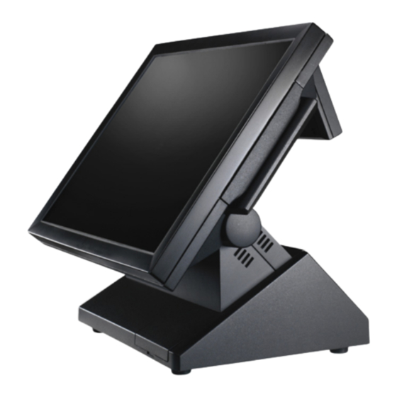
Identifying components This section describes the parts and connectors on the PT-5700. Front-right view Front-right view of PT-5700 Figure 1.2 15-inch TFT LCD touch screen Power LED Power button/USB cover There are two USB connectors under the power button/USB cover and two more USB connectors on the rear of the PT-5700. -
Page 14: Rear-Right View
Rear-right view Figure 1.3 Rear-right view of PT-5700 Customer display cover Magnetic card reader cover Rear cover Rear cover latches Chapter 1 Getting Started ESCRIPTION... -
Page 15: Rear Connectors
Rear connectors Figure 1.4 shows the connectors on the rear of the PT-5700. You must remove the rear cover to access the connectors. See “Removing the rear cover” on page 6. Figure 1.4 Connectors with cables disconnected RJ-45 connector PS/2 mouse connector... -
Page 16: Removing The Rear Cover
Plugging a phone line into the LAN port (RJ-45 connector) can damage the con- nector. Take care to only plug an RJ-45 connector into the LAN port. CAUTION Removing the rear cover Refer to the following to remove the rear cover. Rotate the display until it’s perpendicular. -
Page 17: Attaching The Customer Display
Attaching the customer display The PT-5700 may ship with a customer display attached. If you ordered the display separately, refer to the following to attach it. Remove the rear cover. See “Removing the rear cover” on page 6. Remove the screw. -
Page 18: Adjusting Display Angles
Connect the customer display cable. Align the grooves on the customer display bracket and slide the customer display firmly into place. Secure the display with the two supplied screws. Adjusting display angles The main display can be tilted back from an upright perpendicular position to about 45 degrees as shown in Figure 1.5.The customer display can be tilted as shown in Figure 1.6. -
Page 19: Setup Considerations
Connecting peripheral devices Peripheral devices such as a printer or scanner can be connected to the PT-5700. Refer to the user manual of the device you are connecting for instructions on installing drivers where needed. (Remove the rear cover to access the connec- tors. -
Page 20: Connecting A Cash Drawer
IMPORTANT Remove the rear cover. (See “Removing the rear cover” on page 6.) Connect the RJ-11 cable from the cash drawer to the RJ-11 connector on the PT-5700 as shown in Figure 1.8. Figure 1.8 Connecting a cash drawer Turn on the PT-5700. - Page 21 (B). The power LED (A) turns on. To turn off the PT-5700, shut down the operating system: the main power turns off automatically. You may need to use the main power button to turn off the power, for example if the operating system you are using does not support power down by the OS or if the system crashes or hangs.
- Page 22 Chapter 1 Getting Started...
-
Page 23: Upgrading Components
This chapter describes how to upgrade components for the PT-5700. The following topics are described. • “Safety and precautions” • “Before you begin” on page 14 • “Installing a hard disk drive (HDD)” on page 14 • “Installing a CompactFlash card” on page 15 Safety and precautions Computer components and electronic circuit boards can be damaged by discharges of static electricity. -
Page 24: Chapter 2 Upgrading Components
To prevent scratching the case of the PT-5700, make sure the worktop surface is clean and flat. CAUTION Installing a hard disk drive (HDD) Refer to the following to install a HDD. -
Page 25: Installing A Compactflash Card
The CompactFlash card reader uses an IDE (Integrated Drive Electronics) interface and only supports storage cards. Plug and play is not supported so cards have to be installed before you turn the PT-5700 on. After installing a Compact- Flash card, replace the cover to prevent the card being accidently removed while power is on. - Page 26 Chapter 2 Upgrading Components...
-
Page 27: Chapter 3 Bios Setup Utility
The BIOS (Basic Input and Output System) Setup Utility displays the system's configuration status and provides options to set system parameters. The parameters are stored in battery-backed-up CMOS RAM that saves this informa- tion even when the power is turned off. When the system is turned back on, the system is configured with the values found in CMOS.The following topics are described in this chapter. -
Page 28: Entering The Setup Utility
Entering the Setup Utility When you power on the system, BIOS enters the Power-On Self Test (POST) routines. POST is a series of built-in diagnostics performed by the BIOS. After the POST routines are completed, the following message appears: Press the delete key <Delete> to access the Award BIOS Setup Utility: Figure 3.1 Main BIOS menu BIOS navigation keys... -
Page 29: Using Bios
Date and Time The Date and Time items show the current date and time held by the PT-5700. If you are running a Windows OS, these items are automatically updated whenever you make changes to the Windows Date and Time Properties utility. -
Page 30: Figure 3.3 Ide Primary Master Submenu
Figure 3.3 IDE Primary Master Submenu IDE HDD Auto-Detection Press Enter while this item is highlighted if you want the Setup Utility to automatically detect and configure a hard disk drive on the IDE channel. If you are setting up a new hard disk drive that supports LBA mode, more than one line will appear in the parameter box. -
Page 31: Access Mode
Access Mode This item defines special ways that can be used to access IDE hard disks such as LBA (Large Block Addressing). Leave this value at Auto and the system will automatically decide the fastest way to access the hard disk drive. Press <Esc>... -
Page 32: Virus Warning
CPU Feature • Delay Prior to Thermal -The Delay Prior To Thermal BIOS feature controls the activation of the Thermal Monitor's automatic mode. It allows you to determine when the CPU's Thermal Monitor should be activated in automatic mode after the system boots. For example, with the default value of 16 Minutes, the BIOS activates the Thermal Monitor in automatic mode 16 minutes after the system starts booting up. -
Page 33: Advanced Chipset Features
Security Option If you have installed password protection, this item defines if the password is required at system start up, or if it is only required when a user tries to enter the Setup Utility. The default setting is Setup. MPS Version Control for OS This specifies the version of the Multiprocessor Specification (MPS) to be used. -
Page 34: Init Display First
DRAM Clock/Drive Control (See “DRAM Clock/Drive Control” on page 24.) AGP & P2P Bridge Control (See “AGP & P2P Bridge Control” on page 27.) CPU & PCI Bus Control (See “CPU & PCI Bus Control” on page 27.) Memory Hole This item can be used to reserve memory space for some ISA expansion cards that require it. - Page 35 DRAM Clock This item enables you to manually set the DRAM Clock to 200 MHz. We recommend that you leave this item at the default value. The default value is By SPD. DRAM Timing Set this to the default value to enable the system to automatically set the SDRAM timing by SPD (Serial Presence Detect).
- Page 36 RDSAIT selection Set RDSAIT to 03 (Default value:03) Press <Esc> to return to the Advanced Chipset Features menu. Chapter 3 BIOS Setup Utility...
-
Page 37: Agp & P2P Bridge Control
Select Display Device If you connect an external display to the PT-5700, you can use this setting to turn off LCD and only use the external display. To use dual displays this must be set to CRT+LCD. The Default setting is CRT+LCD. -
Page 38: Figure 3.7 Cpu & Pci Bus Control Menu
Figure 3.7 CPU & PCI Bus Control menu PCI Master 0 WS Write When enabled, writes to the PCI bus are executed with zero wait states. The default setting is Enabled. PCI Delay Transaction The mainboard’s chipset has an embedded 32-bit post write buffer to support delay transactions cycles. Select Enabled to support compliance with PCI specification version 2.1. -
Page 39: Integrated Peripherals
Integrated Peripherals This option defines the operation of peripheral components on the system's input/output ports. Figure 3.8 Integrated Peripherals menu VIA OnChip IDE Device (See “VIA OnChip IDE Device” on page 31.) VIA OnChip PCI Device (See “VIA OnChip PCI Device” on page 32.) SuperIO Device (See “SuperIO Device”... - Page 40 Serial Port 4 Use IRQ This option is used to assign the interrupt request (IRQ) for the onboard serial port 4 (COM4). The default setting is IRQ 5. COM4 With Voltage COM ports can be set to supply both data and power to the peripherals that connect to them. Check if the device you connect needs power from the COM port or if it has its own power supply.
-
Page 41: Via Onchip Ide Device
VIA OnChip IDE Device Use this item to enable or disable the PCI IDE channels that are integrated on the mainboard. Select the item and press <Enter> to open the following menu: Figure 3.9 VIA OnChip IDE Device menu On-Chip SATA Use these items to enable or disable the PCI IDE channels that are integrated on the mainboard. -
Page 42: Via Onchip Pci Device
Primary/Secondary Master/Slave UltraDMA Each IDE channel supports a master device and a slave device. This mainboard supports UltraDMA technology, which provides faster access to IDE devices. If you install a device that supports UltraDMA, change the appropriate item on this list to Auto. You may have to install the UltraDMA driver supplied with this mainboard in order to use an UltraDMA device. -
Page 43: Usb Keyboard Support
ON: Set on to USB emulation. (Default value) USB Keyboard Support Enable this item if you plan to use a keyboard connected through the USB port in a legacy operating system (such as DOS) that does not support Plug and Play. The default setting is Enabled. Press <Esc>... -
Page 44: Power Management Setup Option
UR2 Duplex Mode You can select Half or Full, The default setting is Full. Onboard Parallel Port This option is used to assign the I/O address and IRQ for the onboard parallel port. The default setting is 378/IRQ7. Parallel Port Mode Enables you to set the data transfer protocol for the parallel port. -
Page 45: Acpi Function
NOTE PT-5700. ACPI Suspend Type Use this item to define how the system suspends. In the default, S1(POS), the suspend mode is equivalent to a software power down. -
Page 46: Figure 3.13 Irq/Event Activity Detect Menu
Off: Disabled this function. (Default value) On: Set AC Loss auto restart. Former-Sts: Set AC Loss to former-Sts. IRQ/Event Activity Detect This item opens a submenu that enables you to set events that will resume the system from a power saving mode. Select the item and press <Enter>... - Page 47 LPT & COM When this item is enabled, the system will restart the power-saving timeout counters when any activity is detected on the serial ports, or the parallel port. The default setting is LPT/COM. HDD & FDD When this item is enabled, the system will restart the power-saving timeout counters when any activity is detected on the hard disk drive or the floppy diskette drive.
-
Page 48: Pnp/Pci Configurations
Figure 3.14 IRQs Activity Monitoring menu This menu enables you to set IRQs that will resume the system from a power saving mode. Set any IRQ to Enabled to allow activity at the IRQ to wake up the system from a power saving mode. PnP/PCI Configurations This option configures how PnP (Plug and Play) and PCI expansion cards operate in the system. -
Page 49: Reset Configuration Data
PNP OS Installed Setting this option to Yes allows the PnP OS (instead of BIOS) to assign the system resources such as IRQ and I/O address to the ISA PnP device. The default setting is No. Reset Configuration Data If you enable this item and restart the system, any PnP configuration data stored in the BIOS Setup is cleared from memory. -
Page 50: Pc Health Status
PC Health Status On mainboards that support hardware monitoring, this item lets you monitor the parameters for critical voltages, and critical temperatures. These fields are display only. Figure 3.16 PC Health Status menu Press <Esc> to return to the main menu. Chapter 3 BIOS Setup Utility... -
Page 51: Frequency/Voltage Control
Frequency/Voltage Control This item enables you to set the clock speed and system bus for the system. The clock speed and system bus are deter- mined by the kind of processor you have installed in the system. Figure 3.17 Frequency/Voltage Control menu CPU Clock Ratio The CPU clock ratio setting defines how fast the CPU clock runs relative to the bus speed. -
Page 52: Other Bios Options
Other BIOS Options This section covers the other options that are available from the main menu: Load Fail-Safe Defaults Option This option opens a dialog box that lets you load fail-safe defaults for all appropriate items in the Setup Utility. Follow these instructions: 1. -
Page 53: Set Supervisor And User Passwords Options
Set Supervisor and User Passwords Options These items can be used to install a password. A Supervisor password takes precedence over a User password, and the Supervisor can limit the activities of a User. To install a password, follow these steps: 1. - Page 54 Chapter 3 BIOS Setup Utility...
-
Page 55: Appendix
If failure is detected in an area other than the mainboard (such as the keyboard or an adapter card), an error message is displayed on the screen and testing is stopped. If your system does not successfully complete the POST, but displays a blank screen, have the PT-5700 serviced. Beep Errors at POST There are two kinds of beep codes in the BIOS. -
Page 56: Beep Message Errors At Post
The memory card is not correctly installed or is damaged. OLUTION Replace the battery. Replace the battery. Have the PT-5700 serviced. Have the PT-5700 serviced. Have the PT-5700 serviced. Have the PT-5700 serviced. Have the PT-5700 serviced. Have the PT-5700 serviced. -
Page 57: General Problems
If the same problem occurs, replace the mouse or keyboard. Check that the AC adapter is connected to the PT-5700 and the power cord is plugged into a working electrical outlet. Check that the power is on. (Press the power switch again for confirmation.) -
Page 58: Having The Projector Serviced
If you are unable to solve the problem, you should have the projector serviced. Pack the projector in the original car- ton. (See “Unpacking the PT-5700” on page 1.) Include a description of the problem and a checklist of the steps you took when trying to fix the problem. -
Page 59: Specifications
Specifications Processor Memory Chipset BIOS Onboard graphics On-Board Ethernet On-Board Audio ESCRIPTION Supports VIA Eden family CPU, NANO BGA 1000 / 400 MHz One 200-pin DDR2 SO-DIMM socket North Bridge supports up to 1.0GB DDR2/533 RAM* *Size of memory depends on memory module technology. 1GB is the maximub size of DDR2 RAM CN700 NB –... - Page 60 I/O support/connectors Environment Power Adapter Appendix ESCRIPTION COM 3 PRINTER AUDIO OUT COM 4 AUDIO IN One 15-pin D-sub Connector for CRT Display on I/O board. One RJ-45 port with 2xUSB ports connector. LAN connector has Activity and Link LEDs. BIOS support for boot from LAN, USB-FDD, HDD or USB-CD-ROM.
Need help?
Do you have a question about the PT-5700 and is the answer not in the manual?
Questions and answers