Advertisement
Quick Links
1.
Warnings
Connect the power supply and the display-/output device according to the safety
regulations for electrical equipment. The supply voltage must not exceed the specified
limits.
> Risk of injury, damage to or destruction of the sensor
Avoid shocks and impacts to the sensor. Avoid constant exposure of the sensor to dust
and splashes of water. Avoid exposure of sensor to aggressive materials (detergents,
cooling emulsions).
> Damage to or destruction of the sensor
Read the detailed operation instructions before operating the sensor.
These instructions are available online at www.micro-epsilon.com.
2.
Notes on CE Marking
The following apply to the scanCONTROL 2900/2950-xx/BL:
- EU Directive 2014/30/EU
- EU Directive 2011/65/EU
The sensor is designed for use in industrial environments.
The sensor satisfies the requirements if the guidelines in the operation instructions are
maintained in installation and operation.
3.
Proper Environment
- Protection class:
- Temperature range:
ƒ Operation:
ƒ Storage:
- Humidity:
scanCONTROL 2900/2950BL
Assembly Instructions
scanCONTROL
IP65
0 ... +45 °C (+32 ... +113 °F), for free circulation of air
-20 ... +70 °C (-4 ... +158 °F)
5 - 95 % (non-condensing)
2900/2950BL
Page 1
Advertisement

Related Manuals for MICRO-EPSILON scanCONTROL 29 0 Series


Summary of Contents for MICRO-EPSILON scanCONTROL 29 0 Series
- Page 1 > Damage to or destruction of the sensor Read the detailed operation instructions before operating the sensor. These instructions are available online at www.micro-epsilon.com. Notes on CE Marking The following apply to the scanCONTROL 2900/2950-xx/BL: - EU Directive 2014/30/EU - EU Directive 2011/65/EU The sensor is designed for use in industrial environments.
-
Page 2: Laser Safety
Laser Safety The scanCONTROL 2900/2950-xx/BL sensors operate with a semiconductor laser with a wavelength of 405 nm (visible/blue). Operation of the laser is indicated visually by the LED on the sensor, see operating instructions, Chap. 3.3. When operating the scanCONTROL 29xx sensors, the relevant regulations according to IEC 60825, Part 1 of 05/2014 and the applicable accident prevention regulations must be followed. -
Page 3: Unpacking, Included In Delivery
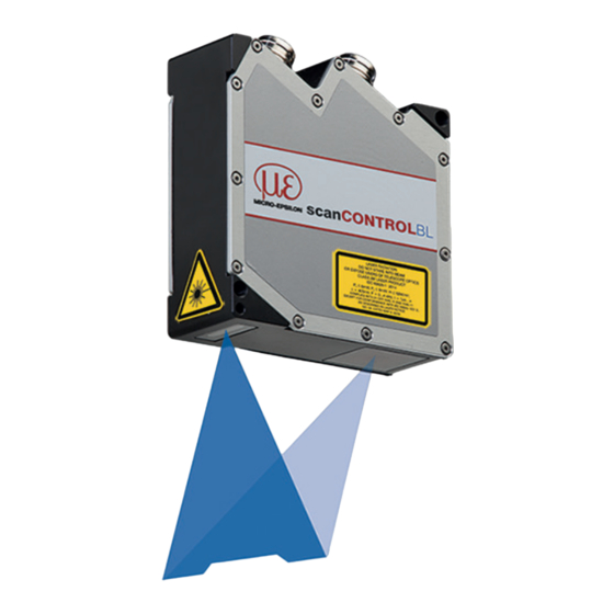
scanCONTROL Fig. 1 Sensor with laser labels Unpacking, Included in Delivery - 1 scanCONTROL 2900/2950-xx/BL sensor with integrated controller - 1 PCR3000-5 multifunction cable, length 5 m; for power supply, trigger and RS422; screw connector and free cable ends - Calibration protocol / assembly instructions - 2 Protective caps scanCONTROL 2900/2950BL Page 3... - Page 4 Connections, LED Indication 1 Ethernet port 2 Multifunction port (Power supply, I/O) Multifunction Port Designation Sensor con- Cable color Notes nector pin PCR3000-x + 11 V - 30 V DC (rated value 24 V); max. 5 W Blue +Laser on/off White Available with SI option -Laser on/off...
- Page 5 RS422, Synchronization The RS422 connection (Pin 11 and 12 of the multifunction port) can be used in either of the following configurations: - RS422 (half-duplex): Load user modes and sensor control, sensor control and transmission of measurement results (Modbus RTU or ASCII format) - Synchronization/triggering: Synchronization or triggering using switching signals Trigger, Encoder, Mode Switching The switching inputs of the multifunction port can either be used for encoder input,...
- Page 6 > Damage to the sensor and /or Ethernet card! - A fixed IP address can be assigned. Use the sensorTOOL program to make specify the sensor settings described above. The program is available online at https://www.micro-epsilon.de/service/download/soft- ware. scanCONTROL 2900/2950BL Page 6...
- Page 7 LED Indication LED Laser on LED state Green: Laser on Green: Measurement active Green, flashes long Data transmission is active Green, flashes short Controller accesses Red, flashes Error code The state LED indicates different error states by flashing. If no flashing occurs for several seconds, no error has occurred. For a detailed description of the error codes, please refer to the operating instructions, Chap.
-
Page 8: Additional Information
Tools operating instructions. You will find details about the individual programs in the respective operating instruc- tions or in the operating instructions of this sensor, Chap. 6.2. You will find the operating instructions online at www.micro-epsilon.com. scanCONTROL 2900/2950BL Page 8... - Page 9 Mount the sensor according to the installation instructions. Install the software. You will find the software online on the product website of the sensor or in the download area: https://www.micro-epsilon. de/2D_3D/laser-scanner/Software/ downloads/. Follow the dialog instructions through the installation process: A.
- Page 10 First Profile Now start the scanCONTROL Configuration Tools software. Click on Display Profiles in the main window. If the software shows the error message No scanCONTROL found in the status line, please check the Ethernet connection between scanCONTROL and PC. On the left side you can adjust the settings for your measurement task.
- Page 11 scanCONTROL 2900/2950BL Page 11...
- Page 12 MICRO-EPSILON Messtechnik GmbH & Co. KG Koenigbacher Str. 15 94496 Ortenburg / Germany, Tel. +49 (0) 85 42/1 68-0 Your local contact: www.micro-epsilon.com/contact/worldwide/ X9771299.204-A032011HDR...
Need help?
Do you have a question about the scanCONTROL 29 0 Series and is the answer not in the manual?
Questions and answers