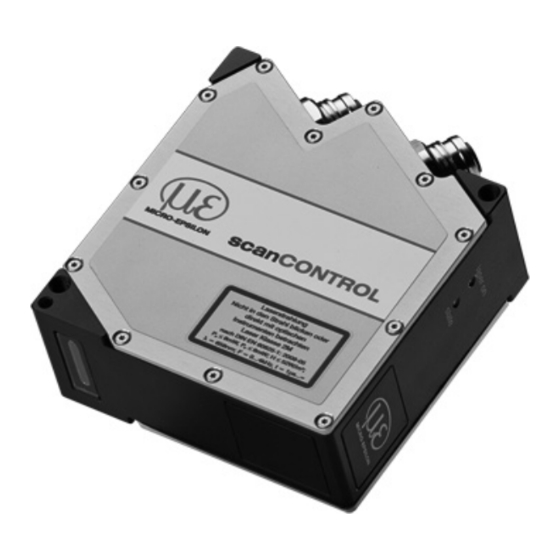
MICRO-EPSILON scanCONTROL 2900 Assembly Instructions Manual
Hide thumbs
Also See for scanCONTROL 2900:
- Assembly instructions manual (12 pages) ,
- Assembly instructions manual (12 pages)
Table of Contents
Advertisement
Quick Links
1.
Warnings
Connect the power supply and the display-/output device in accordance with the
safety regulations for electrical equipment. The power supply must not exceed the
specified limits.
> Danger of injury, damage or destruction of the sensor
Avoid shock and vibration to the sensor. Avoid continuous exposure to dust and spray
on the sensor. Avoid exposure to aggressive materials (e. g. washing agent, penetra-
ting liquids or similar) on the sensor.
> Damage to or destruction of the sensor
Read the detailed instruction manual before operating the sensor. You will find this
manual on the provided CD or online at www.micro-epsilon.com.
2.
Notes on CE Identification
The following applies to the scanCONTROL 2900/2950BL:
- EU directive 2014/30/EU
- EU directive 2011/65/EG, "RoHS" category 9
The sensor is designed for use in industry and satisfies the requirements.
The sensor fulfills the specifications of the EMC requirements, if the instructions in the
manual are followed.
3.
Proper Environment
- Protection class:
- Operating temperature: 0 to +45 °C (+32 to +113 °F), by free circulation of air
- Storage temperature:
- Humidity:
4.
Scope of Delivery of scanCONTROL 2900/2950BL
- 1 Sensor scanCONTROL 2900/2950BL with integrated controller
- 1 Multifunction cable PC2600/2900-5, length 5 m; for power supply, trigger and
RS422; Escha screw connector and free cable ends
- Sensor acceptance report / assembly instructions
- 2 protective caps
- scanCONTROL Demo-CD with drivers, programs and documentation
Assembly Instructions
scanCONTROL
IP 65
-20 to +70 °C ( -4 to +158 °F)
5 - 95 % (non condensing)
2900/2950BL
Advertisement
Table of Contents

Summary of Contents for MICRO-EPSILON scanCONTROL 2900
-
Page 1: Assembly Instructions
> Damage to or destruction of the sensor Read the detailed instruction manual before operating the sensor. You will find this manual on the provided CD or online at www.micro-epsilon.com. Notes on CE Identification The following applies to the scanCONTROL 2900/2950BL: - EU directive 2014/30/EU - EU directive 2011/65/EG, “RoHS“... -
Page 2: Laser Safety
405 nm (visible/blue) . The laser operation is indicated visually by the LED on the sensor. scanCONTROL 2900/2950BL sensors with a maximum laser power up to 8 mW (scanCONTROL 29xx-10/BL up to 7 mW) are classified in Laser Class 2M (IIM). The following information labels are fitted to the sensor housing (front and rear side). - Page 3 - The sensor supports DHCP . This setting is activated by default and has priority over the retrieval in the link-local-net. - The sensor scanCONTROL 2900/2950BL supports Power over Ethernet. If the sensor is connected to a network adapter/switch that...
- Page 4 Multifunction Port Designation Sensor connector Cable color Notes PC2600/2900-x + 11 V - 30 V DC (rated value 24 V); max. 500 mA blue +Laser on/off white optional -Laser on/off brown RS422 red-blue RS422, input respectively output /RS422 gray-pink yellow Digital Input I GND-In1 green...
-
Page 5: Led Displays
External Laser Switching The sensors of the scanCONTROL 29xx/BL-SI series offer this function. Use a serial key switch inside the control circuit to switch off the laser. You will find details for the wiring in the instruction manual, Chap. 5.2.6. LED Displays LED “laser on“... - Page 6 Quick Start: Commissioning, Software Install the software. Please insert the scanCONTROL Demo CD in the CD-ROM device. Follow the dialog through the installation process. A. Reading of installation help B. Installation of software C. Further informations in the online documentation Mount the sensor according to the installation instructions.
- Page 7 First Profile Now start the scanCONTROL Configuration Tools software. Click on “Display Profiles“ in the main window. If the software shows the error message “No scanCONTROL found” in the status line, please check the Ethernet connection between scanCONTROL and PC. On the left side you can adjust the settings for your measurement task, the right side shows the profile data and information about the measurement.
- Page 8 Chap. 6.2. You will find the instruction manu- als online or on the provided CD. www.micro-epsilon.com MICRO-EPSILON Messtechnik GmbH & Co. KG Königbacher Str. 15 94496 Ortenburg / Germany, Tel. +49 (0) 85 42/1 68-0 *X9771299.204-A02*...


Need help?
Do you have a question about the scanCONTROL 2900 and is the answer not in the manual?
Questions and answers