Table of Contents

Related Manuals for MICRO-EPSILON optoNCDT ILR 102 series


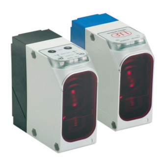
Summary of Contents for MICRO-EPSILON optoNCDT ILR 102 series
- Page 1 Operating Instructions optoNCDT ILR 102x/110x/115x MICRO-EPSILON Eltrotec GmbH Heinkelstr. 2 · 73066 Uhingen / Germany Tel. +49 (0) 7161 / 98872-300 · Fax +49 (0) 7161 / 98872-303 eltrotec@micro-epsilon.de · www.micro-epsilon.com...
- Page 2 Non-contact laser optical distance sensors MICRO-EPSILON Eltrotec GmbH Heinkelstraße 2 73066 Uhingen / Germany Tel. +49 (0) 7161 / 98872-300 Fax +49 (0) 7161 / 98872-303 e-mail info@micro-epsilon.de www.micro-epsilon.com...
-
Page 3: Table Of Contents
Contents Safety ................................ 5 Symbols Used ..............................5 Warnings ................................5 Notes on CE Marking ............................6 Intended Use ..............................6 Proper Environment ............................7 Laser Class ............................... 8 Functional Principle, Technical Data ....................... 9 Sensor Models ..............................9 Functional Principle ............................10 Technical Data ............................... - Page 4 ILR11xx ................................27 6.2.1 Control and Display Elements ...................... 27 6.2.2 Menu Structure ..........................30 6.2.3 Operation Mode..........................31 6.2.4 QuickSet ............................32 6.2.5 Switching Behavior, Hysteresis and Analog Output ..............33 6.2.6 Offset ............................35 6.2.7 Unit ..............................35 6.2.8 Interface and Parameter .......................
-
Page 5: Safety
Safety Safety System operation assumes knowledge of the operating instructions. Symbols Used The following symbols are used in these operating instructions: Indicates a hazardous situation which, if not avoided, may result in minor or moderate injury. Indicates a situation that may result in property damage if not avoided. Indicates a user action. -
Page 6: Notes On Ce Marking
Products which carry the CE mark satisfy the requirements of the EU directives cited and the European harmonized standards (EN) listed therein. The EU Declaration of Conformity is available to the responsible authorities according to EU Directive, article 10, at: MICRO-EPSILON Eltrotec GmbH Heinkelstraße 2 73066 Uhingen / Germany The measuring system is designed for use in industrial environments and meets the requirements. -
Page 7: Proper Environment
Safety Proper Environment - Protection class: IP 67 - Operating temperature: -10 ... +50 °C (+14 ... +122 °F) -20 ° … +50 °C (-4 ... +122 °F) continuous operation - Storage temperature: -30 ... +75 °C (-22 ... +167 °F) - Humidity: 5 - 95 % (non-condensing) - Ambient pressure:... -
Page 8: Laser Class
Laser Class Laser Class The optoNCDT 102x/110x/115x sensors operate with a semiconductor laser for measurements and adjust- ment of the sensor. Laser type, wavelength Laser class ILR1020-6 ILR1021-30 ILR1100-6 / ILR1101-50 / Never deliberately ILR1150-10 / ILR1151-250 look into the laser Measurement laser 1 (I) Infrared, 905 nm... -
Page 9: Functional Principle, Technical Data
Functional Principle, Technical Data Functional Principle, Technical Data Sensor Models The sensors of the series ILR102x/110x/115x use the principle of pulsed light runtime measurement. The sensors measure the distance to a tar- get (ILR1020/1100/1150) or a reflector (ILR1021/1101/1151). The distance measuring is done with an infrared laser. -
Page 10: Functional Principle
Functional Principle, Technical Data Functional Principle With pulse runtime measurement a short light pulse is sent, reflected and registered in the receiver. At the same moment the time is stopped. The outgoing pulse starts a clock and the received pulse stops the clock. The elapsed time (light runtime) is proportional to the light distance. -
Page 11: Technical Data
Functional Principle, Technical Data Technical Data The data apply to the specified surface at constant environment conditions with a minimum operating time of 15 minutes. The switching outputs are short-circuit proof. ILR1020-6 ILR1021-30 ILR1100-6 ILR1101-50 ILR1150-10 ILR1151-250 Model black 6 % 0.2 ... - Page 12 Functional Principle, Technical Data ILR1020-6 ILR1021-30 ILR1100-6 ILR1101-50 ILR1150-10 ILR1151-250 Model 4 - 20 mA / max. load 500 Ohm 4 - 30 mA Analog output free adjustable (teach in) adjustable in 1 mm steps Switching points 30 mm min. 20 mm (adjustable) min.
-
Page 13: Delivery
Delivery Delivery Unpacking, Included in Delivery 1 Sensor optoNCDT102x/110x/115x 1 Operating Instructions 1 CD with configuration software (ILR11xx only) 1 Laser label class 1 Optional accessory, packed separately: 1 Power supply / output cable PC1000 respectively PC1100 with 2 m up to 30 m length 1 Female cable connector You will find optional accessories in appendix, see Chap. -
Page 14: Installation
Installation Installation The sensor optoNCDT102x/110x/115x is an optical sensor for measurements with millimeter accuracy. Pay attention to careful handling during mounting and operation. Sensor Mounting - The sensor is mounted by means of 3 screws type M5 - The laser beam must be directed perpendicularly onto the surface of the target. In case of misalignment it is possible that the measurement results will not always be accurate. -
Page 15: Reflector Mounting
Installation Reflector Mounting The series ILR1021/1101/1151 sensors measure the distance to a reflector. Direct measuring to a target is not possible. Depending on the measuring range different types of reflectors are used. ILR-R700 ILR-R540 ILR-R660 ILR-R460 ILR-R250 ILR-RF250 Fig. 8 Dimensional drawing reflector, dimensions in mm, not to scale Fig. - Page 16 Installation Fig. 10 Reflector orientation It is possible to align the sensor over a max. distance of approximately 50 m using the integrated red light target laser. For larger distances, use the aligning aid (ILR-AA1) listed in the accessories, see Chap. This aligning aid, makes it possible to check the position of the red light target laser spot on the reflector at very long ranges (>100 m).
-
Page 17: Light Spot Geometry
Installation Light Spot Geometry 5.3.1 ILR102x 27.5 4 x 7 10 x 5 3 x 10 4 x 12 Fig. 11 Light spot geometry ILR1020, dimensions in mm, not to scale 27.5 15 x 20 30 x 40 10 x 5 10 m 45 x 60 20 m 30 m... -
Page 18: Ilr11Xx
Installation 5.3.2 ILR11xx 27.5 27.5 20 x 20 10 x 5 10 x 5 3 x 10 10 m 100 x 100 4 x 12 200 x 200 50 m 500 x 500 100 m 10 x 20 250 m 10 m Fig. -
Page 19: Electrical Connection
Installation Electrical Connection The sensors contain 5-pin connectors (ILR102x) or 12-pin connectors (ILR11xx). Bending radius of the supply and output cable (available as an optional accessory, see Chap. PC1x 34 mm (once), 84 mm (permanent) PC11x 47 mm (once), 116 mm (permanent) Switching output <... -
Page 20: Ilr102X
Installation 5.4.1 ILR102x Color Specification PC1000 brown + 18 ... 30 V white Switching output Q . 100 mA blue 0 V (GND) black Switching output Q . 100 mA Fig. 15 Female cable connector, view on solder pin side gray Analog output 4 .. -
Page 21: Ilr11Xx
Installation 5.4.2 ILR11xx Designation Color PC1100 Description white RS422: transmitted data / SSI: Data+ brown Switching output Q1, I . 100 mA green RS422: received data / SSI: Clock+ analog yellow Analog output 4 .. 20 mA (ILR11x0 only) gray Service output Qs, I . -
Page 22: Operation
Operation Operation ILR102x POWER Once the sensor has been connected to the power supply the green LED lights up. 6.1.1 Control and Display Elements LED Q LED menu yellow PWR SLOW 0% analog inv. inv. Fast/Slow 100% analog orange LED Q yellow LED Power Set key... -
Page 23: Switching Point, Analog Output, Slow/Fast Mode
Operation 6.1.2 Switching Point, Analog Output, SLOW/FAST Mode Open control menu Setup Setting switching point Q Press the key for 3 seconds. Toggle Press the key until the For all settings given below, the sensor menu LED lights up. has to be in the control menu. During this time, the target laser used for Position the reflector at the desired mounting the sensor is switched on auto-... - Page 24 Operation Analog-Setup -Setup Setting analog output Setting switching point Q Toggle Toggle Press the key until the menu Press the key until the menu LEDs light up. lights up. Position the reflector at the desired 0 % Position the reflector at the desired point (4 mA), the press the key.
-
Page 25: Automatic Reflector Mode Ilr1020
Operation Factory setting Toggle Press the key for 15 seconds until the menu LEDs flash. The sensor is set to factory setting. 6.1.3 Automatic Reflector Mode ILR1020 Zone A high Qn 1 Qn 2 Function for ILR1020 only. With this mode a scanning zone (window) is set for a signal output so that the detected surface of the background object (automatic reflector) is approximately in midway between the switching points Qn 1 and Qn 2. -
Page 26: Target Dimensions Ilr1020
Operation 6.1.4 Target Dimensions ILR1020 Distance in m Smallest detectable part in relation to the distance. This chart shows typical values measured on a square, white object. 6.1.5 Factory Setting ILR1020 ILR1021 Analog output 0 % 4 mA (6000 mm) 4 mA (30000 mm) Analog output 100 % 20 mA (200 mm) -
Page 27: Ilr11Xx
Operation ILR11xx Once the device has been connected to the power supply the display shows the measured value if a target or POWER a reflector is in the path of the beam. The green LED lights up. The sensor needs a warm-up time of about 15 min for repeatable measurements. - Page 28 Operation Description LED Q lights Switching output Q active yellow lights Switching output Q active Power lights Power supply OK LED Power Error lights Error green LED Error LED Q yellow Fig. 20 Display elements LEDs All parameters can be adjusted and measured values can be read via the integrated serial interface using PC software or your own special application program.
- Page 29 Operation DIST mm DIST INCH In measuring mode the text (depending on unit se- lected) and the actual measured value are displayed. DIST mm 127045 Selecting menu items: Menu items are displayed on the display: < Menu item > With this display it is possible to switch to another menu item with , or select the menu point with Menu item...
-
Page 30: Menu Structure
Operation 6.2.2 Menu Structure Operating mode Only if Password password is active. QuickSet Teach In Offset UNIT <Enter> <Setup> < 0> <MM> OFFSET UNIT Teach In 4564 Teach In Teach In nnnn >MM <ANA Q1 IIII q2 <Set Q1> <Set Q2> LOG>... -
Page 31: Operation Mode
Operation SERIAL RS422 Password Factory <RS422> <ENTER> <OFF> <Preset> <Gray25> SERIAL Password Factory >SSI EXT.Bus <OFF> >OK Search SERIAL Password >EXT.BUS <ON> SERIAL Parameter Setup >RS422 Fig. 22 Proceeding table menu structure 6.2.3 Operation Mode DIST mm DIST INCH In operating mode appears in the first line depend- ing on the active unit. -
Page 32: Quickset
Operation 6.2.4 QuickSet The current measured value is displayed in the first line. In the center of the second line the energy value is displayed as an alignment aid in the form of a bar graph. 4564 Q1 III q2 Q1 and Q2 can be taught directly by pressing the appropriate button (the teach-in function is not possible if SSI mode is active). -
Page 33: Switching Behavior, Hysteresis And Analog Output
Operation 6.2.5 Switching Behavior, Hysteresis and Analog Output Operating mode You can adapt the switching behavior to the local condition when reaching the switching point. The settings for Q1 and Q2 can be done independently of each other. Teach In See the listed switching states below (Mode Qn menu): <Setup>... - Page 34 Operation Variable measuring range (Teach A1, A2 menu) Operation mode Start of measuring range and end of measuring range can be free chosen within the legal measuring range, see Fig. Teach In 25, point A1 and A2. Therewith you change the gradient of <Setup>...
-
Page 35: Offset
Operation 6.2.6 Offset An offset value can be entered or teached-in in the range ±100,000 mm (or corresponding inch value). The measured value is then increased or decreased by the programmed offset value depending on the preceding sign. This can compensate a mounting position which does not correspond with the zero point of the plant. If an offset value is teached-in it is stored with a negative sign, i.e. - Page 36 Operation Interface parameter (RS422 menu) Depending of the setting made in Serial Select the appropriate interface parameters are displayed or altered. Operation mode The following settings are possible: - RS422 (Factory setting): SERIAL Baud rate: 4.8 or 9.6 or 19.2 or 38.4 (Factory setting) or 57.6 kBaud <RS422>...
-
Page 37: Serial Interface (Rs422 Protocol)
Operation 6.2.9 Serial Interface (RS422 Protocol) All commands have the following structure: <STX><Command><[Data]><EOT> All commands are answered by the ILR11xx as follows: <NAK> = the command was not recognized or the data are outside the limit values, or <ACK> = the command was recognized and executed, the command requires no return data, or <Data>... - Page 38 Operation User commands and their meaning Command Name Data to Data from ILR11xx Specification ILR11xx „GAP“ get all All parameters in text format All parameters of the ILR11xx are read: parameters „Fx9xILA $Revision X.XX$“ X.XX: Revision number „pilot is on/off/xx seconds YYYY: User offset [mm] or [10 MIL] on“...
- Page 39 Operation Command Name Data to Data from Specification ILR11xx ILR11xx „GDB“ get energy Energy value 0.. 120 dB Indicates the amount of receiving energy. „GNR“ get serial „xxxxxxxxxx“ Serial number is sent as ASCII text number (max. 24 characters). „GSI“ get error status „DDDDDDD“...
- Page 40 Operation Command Name Data to Data from ILR11xx Specification ILRxx „IH1“ input „000“.. „254“ Hysteresis setting around the switching points Q1 in hysteresis Q1 respectively [mm] or [INCH * 100] 0“..“999“ (INCH) „IH2“ input „000“.. „254“ Hysteresis setting around the switching points Q2 in hysteresis Q2 respectively [mm] or [INCH * 100]...
- Page 41 Operation Command Name Data to Data from ILR11xx Specification ILRxx „IL4“ input limit Offset ... Setting of the second switching point of Q1 in [mm] or Q1 2 +12000+Off- [INCH * 100] set respec- tively Offset .. 48000+Off- „IL5“ input limit Offset ...
-
Page 42: Timing Ssi Compatible Interface
Operation Command Name Data to Data from ILR11xx Specification ILRxx „ESM“ trigger single <meas. value> Request for measured value with single measurement measurement/ output Execute sing. m. „EPW“ write Parameter are stored. parameter page/ execute pa- rameter write 6.2.10 Timing SSI Compatible Interface T = Duration of clock signal, min. -
Page 43: Error Messages
Operation 6.2.11 Error Messages In the event of errors the corresponding error messages appear on the display and the error outputs Qs and Qp (active low) are set according to the following table. The error state can be questioned via the command. -
Page 44: Factory Preset
Instructions for Operation 6.2.12 Factory Preset Factory Preset All settings are reset to delivery state. Go to the menu, see Chap. 6.2.13 Password Password Go to the menu to activate/deactivate the password protection. With delivery the password pro- tection is not active. 1234 Password ON The password is permanently... -
Page 45: Warranty
Within this period, defective parts, except for wearing parts, will be repaired or replaced free of charge, if the device is returned to MICRO-EPSILON Eltrotec with shipping costs prepaid. Any damage that is caused by improper handling, the use of force or by repairs or modifications by third parties is not covered by the liabil- ity for material defects. -
Page 46: Appendix
Appendix | Optional Accessories Appendix Optional Accessories Accessories for optoNCDT ILR 102x PC1000-x Power supply and output cable; 2 and 5 m long, connector straight PC1000/90-x Power supply and output cable; 2. 5 and 10 m long, angle plug optoNCDT ILR 102x/110x/115x Page 46... - Page 47 Appendix | Optional Accessories Accessories for optoNCDT ILR 110x/115x PC1100/-x Power supply and output cable; 3, 5. 10, 20, 30 m long PC1100/90-x Power supply and output cable; 3, 5. 10, 20, 30 m long, angle plug optoNCDT ILR 102x/110x/115x Page 47...
- Page 48 Appendix | Optional Accessories PC1100-x/ USB power supply and output cable; 3 m long Sensor cable with connector; with integrated RS422/USB converter; USB connector for PC; integrated power supply 100 ... 240 VDC FC1100 Female connector for ILR11xx FC1100/90 Female connector for ILR11xx optoNCDT ILR 102x/110x/115x Page 48...
- Page 49 Appendix | Optional Accessories ILR-MA-90 Mounting bracket for sensor (1.10) Dimensions in mm (inches), not to scale R 2.6 (.10) 20 ° R 2.6 (.10) (.16) (.43) 25 (.98) (1.77) (1.97) (.55) ø 3.1 (.12 dia.) optoNCDT ILR 102x/110x/115x Page 49...
- Page 50 Appendix | Optional Accessories LR-FA1 Fine adjustment set for moun- ting bracket, ±3 ° range of Bolt spacer rotation in both directions ±3 ° ±3 ° ILR-AA1 Aligning aid for positioning the sensor on great distances optoNCDT ILR 102x/110x/115x Page 50...
-
Page 51: Factory Setting
Appendix | Factory Setting Factory Setting ILR1020 ILR1021 Analog output 0 % 4 mA (6000 mm) 4 mA (30000 mm) Analog output 100 % 20 mA (200 mm) 20 mA (200 mm) Switching output Q 600 mm N.O. Switching output Q 2500 mm N.O. - Page 52 MICRO-EPSILON Eltrotec GmbH X9751151-A061019HDR Heinkelstr. 2 · 73066 Uhingen / Germany MICRO-EPSILON Eltrotec Tel. +49 (0) 7161 / 98872-300 · Fax +49 (0) 7161 / 98872-303 *X9751151-A06* eltrotec@micro-epsilon.de · www.micro-epsilon.com...
Need help?
Do you have a question about the optoNCDT ILR 102 series and is the answer not in the manual?
Questions and answers