
Related Manuals for H3C SR6602-I


Summary of Contents for H3C SR6602-I
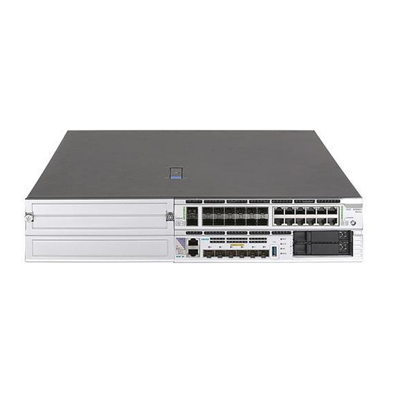
- Page 1 H3C SR6602-I[IE] AI-Powered ICT Converged Gateways Installation Quick Start New H3C Technologies Co., Ltd. http://www.h3c.com Document version: 5W102-20210811...
- Page 2 The information in this document is subject to change without notice. All contents in this document, including statements, information, and recommendations, are believed to be accurate, but they are presented without warranty of any kind, express or implied. H3C shall not be liable for technical or editorial errors or omissions contained herein.
-
Page 3: Table Of Contents
Contents 1 Tool list ······································································································· 1 2 Installation accessories ··············································································· 1 3 Airflow of the device ···················································································· 1 4 Installing the device in a 19-inch rack ························································· 2 Rack-mounting the device by using the mounting brackets and slide rails ························································ 2 Rack-mounting the device by using the mounting brackets and a rack shelf ····················································... -
Page 4: Tool List
Tool list No installation tools are provided with the device. Prepare tools yourself as required. The screwdrivers of different specifications are required to install the device. Prepare flat-head screwdrivers with a tip width of 2.5 mm (0.10 in), 5 mm (0.20 in), and 6 mm (0.24 in). Prepare Phillips screwdrivers with a tip width of 2.5 mm (0.10 in) and 6 mm (0.24 in). -
Page 5: Installing The Device In A 19-Inch Rack
Figure3-1 Airflow of the device Installing the device in a 19-inch rack WARNING! The device is heavy. To avoid bodily injury and device damage, use a minimum of two people to install the device in a rack. Rack-mounting the device by using the mounting brackets and slide rails The device provides multiple chassis rail installation positions on its side panels. - Page 6 Use a mounting bracket to mark the cage nut installation positions on the front rack posts. Install cage nuts at the marked positions. Figure4-1 Attaching cage nuts to the rack Use a slide rail to mark the cage nut installation positions on the rear rack posts. Install cage nuts at the marked positions and attach slide rails to the rack.
- Page 7 Figure4-3 Attaching the mounting brackets and chassis rails to the chassis One person supports the bottom of the device, aligns the chassis rails with the slide rails, and slides the slide rails into the chassis rails until the mounting brackets are flush against the front rack posts.
-
Page 8: Rack-Mounting The Device By Using The Mounting Brackets And A Rack Shelf
Rack-mounting the device by using the mounting brackets and a rack shelf IMPORTANT: Mounting brackets are not used for load bearing but for securing the device to the rack. To use a rack shelf for load bearing, make sure a rack shelf that can bear the weight of the device and its accessories is installed in the rack before rack-mounting the device. - Page 9 Use M4 mounting bracket screws to attach the mounting brackets to both sides of the device front panel. Figure4-7 Attaching the mounting brackets to the device Place the device horizontally on the rack shelf. Move the device along the rack shelf until the mounting brackets of the device are flush against the front the rack posts.
-
Page 10: Installing The Device On A Workbench
Installing the device on a workbench CAUTION: • Make sure the workbench is stable and reliably grounded. • Do not place heavy objects on the device. To install the device on a workbench: Place the device upside down on the workbench and clean the four round holes in the chassis bottom with a dry cloth. -
Page 11: Grounding The Device Mounted On A Workbench
Grounding the device mounted on a workbench If a grounding strip is available at the installation site, you can connect the grounding cable of the device to the grounding strip. To ground the device installed on a workbench by using a grounding strip: Use a Phillips screwdriver to remove the grounding screw from the device chassis. -
Page 12: Installing Internal Removable Components
Figure6-2 Grounding the device mounted in a rack Installing internal removable components WARNING! To avoid injury, remove the access panel only when the fans stop rotating. CAUTION: The internal removable components and cables in the chassis are not hot swappable. To install or maintain them, first power off the device. -
Page 13: Installing A Storage Controller
Installing a storage controller IMPORTANT: No cable is shipped with a storage controller. Purchase one yourself as required. To install a storage controller: Wear an ESD wrist strap and make sure the strap makes good skin contact and is reliably grounded. - Page 14 Figure7-2 Connecting one end of the storage controller cable to the storage controller Remove the access panel. a. Face the front panel of the device and use a Phillips screwdriver to unlock the screw on the locking lever. b. Press the blue unlock button on the locking lever to release the locking lever, and pull the lever upward.
- Page 15 Face the rear panel of the device, use a Phillips screwdriver to remove the screws from the riser module blank, and lift the riser module blank from the device. Figure7-4 Removing the riser module blank Remove the cable from the drive backplane. The cable is used by the system to identify the external SATA drives.
- Page 16 Figure7-5 Removing the cable from the drive backplane Connect the other end of the storage controller cable to the drive backplane and use a cable clamp to secure the storage controller cable to the side panel of the storage controller. Figure7-6 Connecting the storage controller cable to the drive backplane...
- Page 17 Install the riser module installed with the storage controller in the device: a. Align the front tabs of the riser module with the guide rails on the system board and align the captive screw with the screw hole on the system board. b.
- Page 18 Figure7-8 Securing the riser module to the device 11. Install the access panel: a. Face the front panel of the device, place the access panel on top of the device chassis, and align the pegs inside the access panel with the slots on the device side panels. b.
-
Page 19: Installing A Gpu
Installing a GPU IMPORTANT: • A GPU support bracket and three screws are shipped with a riser module. Keep them secure before installing a GPU. • Use the GPU support bracket and screws provided with the riser module to install a GPU in the riser module. -
Page 20: Installing A Dimm
Use screws to secure the riser module to the chassis. For more information, see "Installing a storage controller." 10. Install the access panel. For more information, see "Installing a storage controller." Installing a DIMM IMPORTANT: For system identification, use the DIMMs recommended by H3C. To install a DIMM:... -
Page 21: Installing An M.2 Ssd Drive
Installing an M.2 SSD drive IMPORTANT: • For system identification, use M.2 SSD drives recommended by H3C. • The M.2 SSD drive screw is shipped with the document bag for the chassis. Before installing an M.2 SSD drive, keep the screw secure. -
Page 22: Installing External Removable Components
Insert the golden plating end of the M.2 SSD drive slowly into the M.2 slot at an angle. Slightly press the other end of the golden plating until the golden plating of the M.2 SSD drive is in close contact with the connector in the M.2 slot. Use a Phillips screwdriver to screw the M.2 SSD drive into place. -
Page 23: Installing Mic-X Interface Cards
Installing MIC-X interface cards CAUTION: • Do not install a MIC-X interface card when the device is operating. • To avoid configuration loss of a MIC-X interface card, first install it on a FIP module, and then install the FIP module with it on the device. •... -
Page 24: Installing A Fip Module
Figure8-2 Installing a MIC-X interface card Install the FIP with the MIC-X interface card in the target slot on the device. For the installation procedure, see "Installing a FIP module." Installing a FIP module CAUTION: • The FIP modules are hot swappable. •... -
Page 25: Installing Sata Drives
RAID configuration as indicated by the LED without power off the device. To remove a SATA drive not in RAD configuration, you must first power off the device. • For system identification, use SATA drives recommended by H3C. To install a SATA drive: Wear an ESD wrist strap and make sure the strap makes good skin contact and is reliably grounded. -
Page 26: Installing Power Supplies
Remove the filler panel from the SATA drive slot and keep the removed filler panel secure. Press the red button on the SATA drive tray to release the locking lever. Push the SATA drive slowly into the slot along the guide rails and then close the locking lever. Figure8-6 Installing a SATA drive Installing power supplies CAUTION:... -
Page 27: Connecting Power Cords
Unpack the power supply and verify that the power supply model is correct. Correctly orient the power supply with the power supply slot. Grasp the handle of the power supply with one hand and support its bottom with the other, and slide the power supply slowly along the guide rails into the slot. -
Page 28: Connecting A Dc Power Cord
Figure9-1 Connecting an AC power cord Connecting a DC power cord Wear an ESD wrist strap. Make sure the wrist strap makes good skin contact and is reliably grounded. Use a flat-head screwdriver to loosen the screws on the protective plate over the DC power receptacle and then remove the plate. - Page 29 Connect the female connector of the power cord to the power receptacle on the power supply. Close the cable clamp and slide it forward until it is flush against the edge of the female connector. Connect the other end of the power cord to an AC or high-voltage DC power source. Figure9-3 Connecting a high voltage DC power cord...
Need help?
Do you have a question about the SR6602-I and is the answer not in the manual?
Questions and answers