H3C MSR3610-X1 Installation Manual
Gigabit ethernet integrated service gateway
Hide thumbs
Also See for MSR3610-X1:
- Installation quick manual (4 pages) ,
- Command reference manual (389 pages) ,
- Installation, quick start (5 pages)

Subscribe to Our Youtube Channel
Related Manuals for H3C MSR3610-X1


Summary of Contents for H3C MSR3610-X1
- Page 1 H3C MSR3610-X1 Gigabit Ethernet Integrated Service Gateway Installation Guide New H3C Technologies Co., Ltd. http://www.h3c.com Document version: 6W100-20190108...
- Page 2 The information in this document is subject to change without notice. All contents in this document, including statements, information, and recommendations, are believed to be accurate, but they are presented without warranty of any kind, express or implied. H3C shall not be liable for technical or editorial errors or omissions contained herein.
- Page 3 Preface The H3C MSR3610-X1 Gigabit Ethernet Integrated Service Gateway Installation Guide includes seven chapters, which describe the preparing for installation, installing the router, replacement procedure, troubleshooting, chassis views and technical specifications, LEDs, and slot arrangement. This preface includes the following topics about the documentation: •...
- Page 4 Convention Description Multi-level menus are separated by angle brackets. For example, File > Create > > Folder. Symbols Convention Description An alert that calls attention to important information that if not understood or followed WARNING! can result in personal injury. An alert that calls attention to important information that if not understood or followed CAUTION: can result in data loss, data corruption, or damage to hardware or software.
- Page 5 It is normal that the port numbers, sample output, screenshots, and other information in the examples differ from what you have on your device. Documentation feedback You can e-mail your comments about product documentation to info@h3c.com. We appreciate your comments.
-
Page 6: Table Of Contents
Contents Preparing for installation ···································································· 1 Safety recommendations ············································································································· 1 Safety symbols ··················································································································· 1 General safety recommendations ··························································································· 1 Electricity safety ·················································································································· 1 Examining the installation site ······································································································· 1 Temperature and humidity ····································································································· 2 ... - Page 7 Symptom ························································································································· 29 Solution ··························································································································· 29 Appendix A Chassis views and technical specifications ·························· 30 Chassis views ························································································································· 30 MSR3610-X1 ···················································································································· 30 MSR3610-X1-DP ·············································································································· 31 MSR3610-X1-DC ·············································································································· 31 MSR3610-X1-DP-DC ········································································································· 32 Technical specifications ············································································································· 33 ...
-
Page 8: Preparing For Installation
Preparing for installation The H3C MSR3610 router series includes the models in Table Table 1 H3C MSR3610 router series models Model (on the front panel) Product code H3C MSR3610 Series RT-MSR3610-X1 H3C MSR3610 Series RT-MSR3610-X1-DP H3C MSR3610 Series RT-MSR3610-X1-DC H3C MSR3610 Series... -
Page 9: Temperature And Humidity
Temperature and humidity Make sure the temperature and humidity in the equipment room meet the requirements described Table • Lasting high relative humidity can cause poor insulation, electricity leakage, mechanical property change of materials, and metal corrosion. • Lasting low relative humidity can cause washer contraction and ESD and cause problems including loose mounting screws and circuit failure. -
Page 10: Esd Prevention
Figure 1 Airflow through the device To ensure good ventilation, follow these guidelines: • The air inlet and outlet vents are not blocked, and a minimum of 10 cm (3.94 in) of clearance is reserved around the chassis. • The installation site has a good cooling system. ESD prevention CAUTION: Check the resistance of the ESD wrist strap for safety. -
Page 11: Lightning Protection
• Electromagnetic wave radiation. • Common impedance (including the grounding system) coupling. To prevent EMI, use the following guidelines: • Take effective measures to filter interference from the power grid. • Keep the device far away from radio transmitting stations, radar stations, and high-frequency devices. -
Page 12: Pre-Installation Checklist
Figure 3 Installation accessories Pre-installation checklist Table 5 Pre-installation checklist Item Requirements Result • A minimum clearance of 10 cm (3.9 in) is reserved around the air inlet and outlet vents. Ventilation • The installation site has a good ventilation system. - Page 13 Item Requirements Result • The device is reliably grounded. • The AC power receptacle is reliably grounded. • (Optional.) Port lightning protectors are available. Lightning protection • (Optional.) Power lightning protectors are available. • (Optional.) Signal cable lightning protectors are available.
-
Page 14: Installing The Device
• Keep the tamper-proof seal on a mounting screw on the chassis cover intact, and if you want to open the chassis, contact H3C for permission. Otherwise, H3C shall not be liable for any consequence. - Page 15 Figure 4 Installation flowchart Start Workbench-mounting Rack-mounting Determine the installation position Mount the device on a Mount the device in a rack workbench Ground the device Install interface modules Install a hard disk Install a micro SD card Connect interface cables Connect the device to the configuration terminal Connect the power cord...
-
Page 16: Mounting The Device On A Workbench
Mounting the device on a workbench IMPORTANT: • Make sure the workbench is clean, stable, and reliably grounded. • Maintain a minimum clearance of 10 cm (3.9 in) around the device for heat dissipation. • Do not place heavy objects on the device. To mount the device on a workbench: Place the device upside down on the workbench and attach the rubber feet to the four round holes in the chassis bottom. -
Page 17: Installing The Device In A Rack
Installing the device in a rack Device dimensions and rack requirements Figure 7 Device dimensions Table 6 Device dimensions and rack requirements Chassis dimensions Rack requirements • Height—43.6 mm (1.72 in)/1 RU • Width—440 mm (17.32 in) • A minimum of 0.6 m (1.97 ft) in depth (recommended) •... - Page 18 To install the device in a rack: Use a mounting bracket to mark the cage nut installation holes in the front rack posts, as shown Figure Make sure the cage nut installation holes on the front rack posts are on a horizontal line. Figure 8 Marking cage nut installation holes Install cage nuts, as shown in Figure...
- Page 19 Figure 10 Attaching mounting brackets to the device Put the device in the rack. Use M6 screws to attach the mounting brackets on the device to the front rack posts, as shown in Figure Figure 11 Securing the device to the rack...
-
Page 20: Grounding The Device
Grounding the device CAUTION: • Correctly connecting the grounding cable is crucial to lightning protection and EMI protection. When you install and use the device, first ground the device reliably. • Ensure a minimum resistance of 5 ohms between the device and the ground. A grounding cable is provided with the device. -
Page 21: Grounding The Device With A Grounding Strip
Figure 13 Grounding the device through the grounding terminal on the rack Grounding the device with a grounding strip If a grounding strip is available at the installation site, connect the grounding cable to the grounding strip. To ground the device with a grounding strip: Remove the grounding screw from the grounding hole in the rear panel of the chassis. -
Page 22: Grounding The Device By Burying A Grounding Conductor In The Earth Ground
Figure 14 Grounding the device with a grounding strip Grounding the device by burying a grounding conductor in the earth ground If the installation site does not have any grounding strips, but earth ground is available, hammer a 0.5 m (1.64 ft) or longer angle iron or steel tube into the earth ground to serve as a grounding conductor. The steel tube must be zinc-coated. -
Page 23: Installing A Hard Disk
Figure 16 Installing the SIC Installing a hard disk Only the MSR3610-X1 and MSR3610-X1-DP support a hard disk. No hard disk is provided with the device. To user a hard disk, purchase one from H3C. To install a hard disk:... -
Page 24: Installing A Micro Sd Card
Figure 18 Installing the hard disk Installing a micro SD card No micro SD card is provided with the device. To use a micro SD card, purchase one yourself. When you install a micro SD card, do not use excessive force to avoid damaging the micro SD card slot. -
Page 25: Connecting An Optical Fiber To A Fiber Port
Figure 20 Connecting the device to a terminal Connecting an optical fiber to a fiber port WARNING! Do not stare into any fiber port when you connect an optical fiber. The laser light emitted from the optical fiber might hurt your eyes. Follow these guidelines when you connect a fiber cable: •... -
Page 26: Connecting The Console Cable And Setting Terminal Parameters
Connecting the console cable and setting terminal parameters To access the device for the first time, use a console cable to connect the console port on the device. Connecting the console cable CAUTION: The serial ports on PCs do not support hot swapping. To connect a PC to an operating device, first connect the PC end. -
Page 27: Connecting The Ac Power Cord
Connecting the AC power cord Make sure the device is reliably grounded. Connect one end of the power cord to the AC-input receptacle on the device. Use a bail latch to secure the plug of the power cord in place. Connect the other end of the power cord to the AC power source. -
Page 28: Verifying The Installation
Figure 24 Connecting the DC power cord Verifying the installation Verify the following items before you power on the device: • There is enough space around the device for heat dissipation. • The interface modules are installed correctly. • The device, rack, and power source are reliably grounded. •... - Page 29 Press Ctrl+T to start heavy memory test. Booting Normal Extended BootWare The Extended BootWare is self-decompressing..Done. **************************************************************************** H3C MSR3610 BootWare, Version 1.01 **************************************************************************** Copyright (c) 2004-2017 New H3C Technologies Co., Ltd. Compiled Date : Apr 12 2016 CPU ID : 0x11 Memory Type...
-
Page 30: Replacement Procedure
• Keep the tamper-proof seal on a mounting screw on the chassis cover intact, and if you want to open the chassis, contact H3C for permission. Otherwise, H3C shall not be liable for any consequence. -
Page 31: Replacing A Hard Disk
Replacing a hard disk CAUTION: • To remove the hard disk when the device is operating, press the HD button for over five seconds. When the LED for the hard disk turns off, you can remove the hard disk. You can also use the umount command to unmount the file system and remove the hard disk after the unmount operation succeeds. -
Page 32: Replacing A Micro Sd Card
Replacing a micro SD card CAUTION: • A micro SD card is not hot swappable. If the micro SD card needs to be replaced when the device is operating, execute the umount command before the replacement. • Do not use excessive force when you replace a micro SD card to avoid damaging the micro SD card slot. - Page 33 Figure 30 Removing a transceiver module...
-
Page 34: Troubleshooting
• Keep the tamper-proof seal on a mounting screw on the chassis cover intact, and if you want to open the chassis, contact H3C for permission. Otherwise, H3C shall not be liable for any consequence. -
Page 35: No Display On The Configuration Terminal
Stop bits—1. Flow control—None. Emulation—VT100. Verify that the console cable is in good condition. If the problem persists, contact H3C Support. Garbled display on the configuration terminal Symptom The configuration terminal has garbled display when the device is powered on. -
Page 36: Solution
To resolve the problem: Verify that the serial console cable is in good condition. Verify that the port settings are correct. If the problem persists, contact H3C Support. Interface module failure Symptom An interface module is installed in the device, but the LED for the interface module is not on after the device is powered on. -
Page 37: Appendix A Chassis Views And Technical Specifications
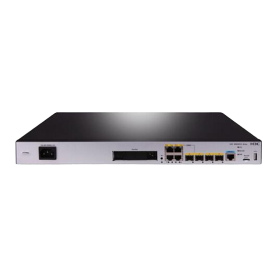
Appendix A Chassis views and technical specifications Chassis views The figures in this section are for illustration only. MSR3610-X1 Figure 31 Front panel (1) AC power receptacle (2) Hard disk slot (3) HD button (4) Gigabit Ethernet port GE1 (5) Gigabit Ethernet port GE3... -
Page 38: Msr3610-X1-Dp
MSR3610-X1-DP Figure 33 Front panel (1) AC power receptacle (PWR1) (2) Hard disk slot (3) HD button (4) Gigabit Ethernet port GE1 (5) Gigabit Ethernet port GE3 (6) SFP ports SFP2 to SFP5 (7) Console port (8) Micro SD card slot... -
Page 39: Msr3610-X1-Dp-Dc
(1) SIC slot 4 (2) SIC slot 3 (3) SIC slot 2 (4) SIC slot 1 (5) Grounding terminal MSR3610-X1-DP-DC Figure 37 Front panel (1) DC power receptacle (2) Gigabit Ethernet port GE1 (3) Gigabit Ethernet port GE3 (4) SFP ports SFP2 to SFP5... -
Page 40: Technical Specifications
Technical specifications Table 8 Technical specifications MSR3610-X1-DP-D Item MSR2600-10-X1 MSR3610-X1-DP MSR3610-X1-DC Console port USB port 4, including two 4, including two 4, including two 4, including two GE port copper combo ports copper combo ports copper combo ports copper combo ports... -
Page 41: Appendix B Leds
Appendix B LEDs MSR3610-X1 Figure 39 MSR3610-X1 LEDs (2) LEDs for Gigabit Ethernet ports (1) Hard disk LED (3) LED for SFP fiber port SFP2 GE0 to GE3 (4) LED for SFP fiber port SFP3 (5) LED for SFP fiber port SFP4... -
Page 42: Msr3610-X1-Dc
MSR3610-X1-DC Figure 41 MSR3610-X1-DC LEDs (2) LEDs for Gigabit Ethernet ports (1) Power status LED (PWR) (3) LED for SFP fiber port SFP2 GE0 to GE3 (4) LED for SFP fiber port SFP3 (5) LED for SFP fiber port SFP4... - Page 43 Status Description The Micro SD card is in position and has passed the Green test. The system is accessing the Micro SD card and Flashing green at 8 Hz Micro SD card LED data is being sent and received. (MicroSD) Yellow The Micro SD card has failed.
-
Page 44: Appendix C Slot Arrangement And Interface Numbering
The device provides SIC slots. The fixed ports on the front panel of the device are in slot 0. Table 9 Slot arrangement and interface numbering Model Slot arrangement Interface numbering • In standalone mode: MSR3610-X1 The interface is numbered in the x/y format. x represents MSR3610-X1- the slot number and y represents the interface number.
Need help?
Do you have a question about the MSR3610-X1 and is the answer not in the manual?
Questions and answers