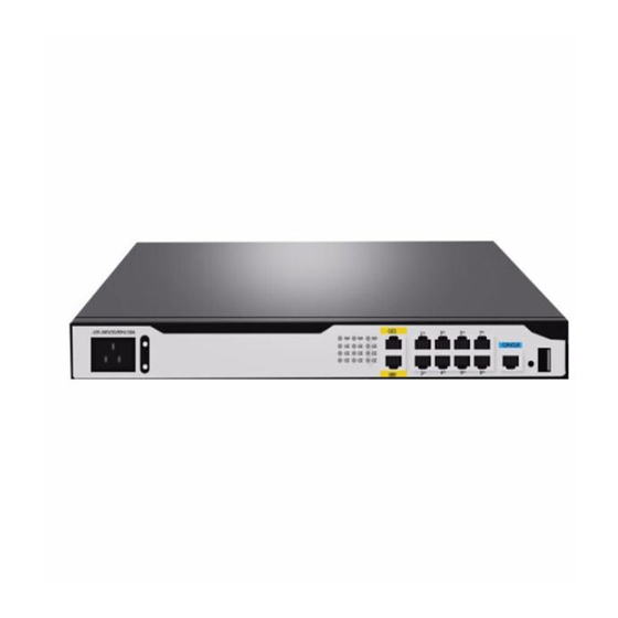
H3C MSR2600-6-X1 Installation Manual
Gigabit ethernet integrated service gateway
Hide thumbs
Also See for MSR2600-6-X1:
- Installation, quick start (4 pages) ,
- Command reference manual (69 pages) ,
- Manual (45 pages)

Subscribe to Our Youtube Channel
Related Manuals for H3C MSR2600-6-X1


Summary of Contents for H3C MSR2600-6-X1
- Page 1 H3C MSR2600-6-X1[10-X1] Gigabit Ethernet Integrated Service Gateway Installation Guide New H3C Technologies Co., Ltd. http://www.h3c.com Document version: 6W103-20180505...
- Page 2 The information in this document is subject to change without notice. All contents in this document, including statements, information, and recommendations, are believed to be accurate, but they are presented without warranty of any kind, express or implied. H3C shall not be liable for technical or editorial errors or omissions contained herein.
- Page 3 Preface The H3C MSR2600-6-X1[10-X1] Gigabit Ethernet Integrated Service Gateway Installation Guide includes seven chapters, which describe the preparing for installation, installing the gateway, replacement procedure, troubleshooting, chassis views and technical specifications, LEDs, and slot arrangement. This preface includes the following topics about the documentation: •...
- Page 4 Convention Description Multi-level menus are separated by angle brackets. For example, File > Create > > Folder. Symbols Convention Description An alert that calls attention to important information that if not understood or followed WARNING! can result in personal injury. An alert that calls attention to important information that if not understood or followed CAUTION: can result in data loss, data corruption, or damage to hardware or software.
- Page 5 It is normal that the port numbers, sample output, screenshots, and other information in the examples differ from what you have on your device. Documentation feedback You can e-mail your comments about product documentation to info@h3c.com. We appreciate your comments.
-
Page 6: Table Of Contents
Contents Preparing for installation ···································································· 1 Safety recommendations ············································································································· 1 Safety symbols ··················································································································· 1 General safety recommendations ··························································································· 1 Electricity safety ·················································································································· 1 Examining the installation site ······································································································· 1 Temperature and humidity ····································································································· 1 Cleanliness ························································································································ 2 Cooling system ··················································································································· 2 ESD prevention ···················································································································... - Page 7 Reset button usage guidelines ····························································································· 29 Appendix A Chassis views and technical specifications ·························· 30 Chassis views ························································································································· 30 MSR2600-6-X1 ················································································································· 30 MSR2600-10-X1 ··············································································································· 31 Technical specifications ············································································································· 31 Appendix B LEDs ··········································································· 33 MSR2600-6-X1 ······················································································································· 33 MSR2600-10-X1 ······················································································································ 33 Appendix C Slot arrangement ···························································...
-
Page 8: Preparing For Installation
Preparing for installation Safety recommendations Safety symbols When reading this document, note the following symbols: WARNING means an alert that calls attention to important information that if not understood or followed can result in personal injury. CAUTION means an alert that calls attention to important information that if not understood or followed can result in data loss, data corruption, or damage to hardware or software. -
Page 9: Cleanliness
Table 1 Temperature and humidity requirements Temperature Humidity Operating temperature: 0°C to 45°C (32°F to 113°F) 5% RH to 95% RH, noncondensing Storage temperature: –40°C to +70°C (–40°F to +158°F) Cleanliness Dust buildup on the chassis might result in electrostatic adsorption, which causes poor contact of metal components and contact points, especially when indoor relative humidity is low. -
Page 10: Esd Prevention
Figure 1 Airflow through the chassis To ensure good ventilation, follow these guidelines: • Maintain a minimum clearance of 10 cm (3.94 in) around the air inlet and outlet vents. • Make sure the installation site has a good ventilation system. ESD prevention Preventing electrostatic discharge To prevent electrostatic discharge (ESD), follow these guidelines:... -
Page 11: Emi Prevention
EMI prevention All electromagnetic interference (EMI) sources, from outside or inside of the gateway and application system, adversely affect the gateway in the following ways: • A conduction pattern of capacitance coupling. • Inductance coupling. • Electromagnetic wave radiation. • Common impedance (including the grounding system) coupling. -
Page 12: Installation Tools And Accessories
Figure 2 Installation tools Figure 3 Installation accessories M4 mounting Rubber feet Mounting brackets M6 rack screw Grounding cable bracket screw Cage nut Power cord clasp Removable cable tie Console cable Power cord (for the MSR2600-10-X1 ) (user supplied) (for the MSR2600-6-X1) -
Page 13: Pre-Installation Checklist
Pre-installation checklist Item Requirements • A minimum clearance of 100 mm (3.94 in) is reserved around the air inlet and outlet vents. Ventilation • The installation site has a good ventilation system. Operating temperature: 0°C to 45°C (32°F to 113°F) Temperature Storage temperature: –40°C to +70°C (–40°F to +158°F) Humidity... -
Page 14: Installing The Gateway
• Keep the tamper-proof seal on a mounting screw on the chassis cover intact, and if you want to open the chassis, contact H3C for permission. Otherwise, H3C shall not be liable for any consequence. -
Page 15: Installing The Gateway
Connect the power cord Verify the installation Power on the gateway Troubleshoot the gateway Operating correctly? Power off the gateway Installing the gateway The installation procedure is the same for the MSR2600-6-X1 and 2600-10-X1 gateways. The following figures use the MSR2600-10-X1 gateway. -
Page 16: Mounting The Gateway On A Workbench
Mounting the gateway on a workbench IMPORTANT: • Make sure the workbench is clean, stable, and reliably grounded. • Maintain a minimum clearance of 100 mm (3.94 in) around the gateway for heat dissipation. • Do not place heavy objects on the gateway. To mount the gateway on a workbench: Place the gateway upside down on the workbench and attach the rubber feet to the four round holes in the chassis bottom. -
Page 17: Mounting The Gateway In A Rack
Mounting the gateway in a rack Gateway dimensions and rack requirements Figure 6 MSR2600-6-X1 gateway dimensions Mounting bracket 60 mm (2.36 in) E1 cable Power cord 60 mm 300 mm (2.36 in) (11.81 in) - Page 18 Depth—420 mm (16.54 in) A minimum of 80 mm (3.15 in) between the front rack posts and 300 mm (11.81 in) for the chassis MSR2600-6-X1 the front door 60 mm (2.36 in) for connecting the • A minimum of 360 mm (14.17 in)
- Page 19 To install the gateway in a rack: Use a mounting bracket to mark the cage nut installation holes in the front rack posts, as shown in Figure Make sure the cage nut installation holes on the front rack posts are on a horizontal line. Figure 8 Marking cage nut installation holes Install cage nuts, as shown in Figure...
-
Page 20: Grounding The Gateway
Figure 10 Attaching mounting brackets to the gateway Use M6 screws to attach the mounting brackets on the gateway to the front rack posts, as shown in Figure Figure 11 Securing the gateway to the rack Grounding the gateway CAUTION: •... - Page 21 Grounding the gateway through the grounding terminal on the rack IMPORTANT: Make sure the rack is reliably grounded before grounding the gateway. To ground the gateway through the grounding terminal on the rack: Remove the grounding screw from the grounding hole in the rear panel of the chassis. Use the grounding screw to attach the ring terminal of the grounding cable to the grounding hole.
- Page 22 Figure 13 Grounding the gateway through the grounding terminal on the rack Grounding the gateway with a grounding strip If a grounding strip is available at the installation site, connect the grounding cable to the grounding strip. To ground the gateway with a grounding strip: Remove the grounding screw from the grounding hole in the rear panel of the chassis.
-
Page 23: Installing Interface Modules
Figure 14 Grounding the gateway with a grounding strip Grounding the gateway by burying a grounding conductor in the earth ground If the installation site does not have any grounding strips, but earth ground is available, hammer a 0.5 m (1.64 ft) or longer angle iron or steel tube into the earth ground to serve as a grounding conductor. -
Page 24: Connecting Interface Cables
Figure 15 Removing the filler panel from a SIC slot Figure 16 Installing a SIC Connecting interface cables Connect cables to the interfaces on the gateway before powering on the gateway. The following procedure connects cables for Ethernet ports. For cable connection procedures for other types of ports, see the interface module manuals. - Page 25 • Make sure the Tx and Rx ports on a transceiver module are connected to the Rx and Tx ports on the peer end, respectively. Only an MSR2600-6-X1 gateway supports transceiver modules. To connect an optical fiber for a fiber port: Pivot the bail latch of the transceiver module up so that it catches a knob on the top of the transceiver module.
-
Page 26: Connecting The Console Cable And Setting Terminal Parameters
Figure 18 Connecting an optical fiber Connecting the console cable and setting terminal parameters To access the gateway at the first time, you can only use a console cable to connect the console port on the gateway to a configuration terminal. Connecting the console cable CAUTION: The serial ports on PCs do not support hot swapping. -
Page 27: Connecting The Ac Power Cord
Figure 19 Connecting the console port to a configuration terminal Setting configuration terminal parameters To configure and manage the gateway through the console port, you must run a terminal emulator program, TeraTermPro or PuTTY, on your PC. You can use the emulator program to connect a network device, a Telnet site, or an SSH site. -
Page 28: Verifying The Installation
Figure 20 Connecting the AC power cord for an MSR2600-6-X1 gateway Figure 21 Connecting the AC power cord for an MSR2600-10-X1 gateway Verifying the installation Verify the following items before you power on the gateway: • There is enough space around the gateway for heat dissipation. -
Page 29: Starting The Gateway
Press Ctrl+D to access BASIC-BOOTWARE MENU... Booting Normal Extended BootWare The Extended BootWare is self-decompressing..Done. **************************************************************************** H3C MSR2600-10-x1 BootWare, Version 1.07 **************************************************************************** Copyright (c) 2004-2017 New H3C Technologies Co., Ltd. Compiled Date : May 6 2015 CPU ID : 0x1... - Page 30 Press Enter. The gateway is ready to configure when you see the following prompt: <Sysname> Configure basic settings for the gateway. For information about configuring basic setting for the gateway, see H3C MSR Gateways Fundamentals Configuration Guide (V7) and H3C MSR Gateways Fundamentals Command Reference (V7).
-
Page 31: Replacement Procedure
Figure Figure 23 Installing a filler panel Replacing a transceiver module Only an MSR2600-6-X1 gateway supports transceiver modules. To replace a transceiver module: Remove the optical fibers from the transceiver module. Release and pull down the bail latch on the transceiver module. - Page 32 Figure 24 Removing a transceiver module...
-
Page 33: Troubleshooting
• Keep the tamper-proof seal on a mounting screw on the chassis cover intact, and if you want to open the chassis, contact H3C for permission. Otherwise, H3C shall not be liable for any consequence. -
Page 34: No Display On The Configuration Terminal
Stop bits—1. Flow control—None. Emulation—VT100. Verify that the console cable is in good condition. If the issue persists, contact H3C Support. Garbled display on the configuration terminal Symptom The configuration terminal has garbled display when the gateway is powered on. -
Page 35: Interface Module Failure
Verify that the serial console cable is in good condition. Verify that the port settings are correct. If the issue persists, contact H3C Support. Interface module failure Symptom An interface module is installed in the gateway, but the LED for the interface module is not on after the gateway is powered on. -
Page 36: Scenario 3
Scenario 3 Symptom The gateway crashes. Solution Press the RESET button for a short time to reboot the gateway. Reset button usage guidelines The RESET button is used to reboot the system or restore the factory settings. • To reboot the gateway, press the RESET button for a short time. •... -
Page 37: Appendix A Chassis Views And Technical Specifications
Appendix A Chassis views and technical specifications Chassis views The following figures are for illustration only. MSR2600-6-X1 Figure 25 Front panel (1) Power receptacle (2) Gigabit Ethernet copper port GE0 (3) Gigabit Ethernet copper ports GE1 to GE4 (4) Gigabit Ethernet fiber port SFP5... -
Page 38: Msr2600-10-X1
Figure 28 Rear panel (1) SIC 3 (2) SIC 2 (3) SIC 1 (4) Grounding terminal Technical specifications Table 6 Technical specifications Item MSR2600-6-X1 MSR2600-10-X1 Console/AUX port Console port USB port GE copper port GE fiber port Reset button Memory... - Page 39 Item MSR2600-6-X1 MSR2600-10-X1 Dimensions (H × W × D) 44.2 × 360 × 300 mm (1.74 × 14.17 × 44.2 × 360 × 303.5 mm (1.74 × (excluding rubber feet and 11.81 in) 14.17 × 11.95 in) mounting brackets) Rated AC voltage...
-
Page 40: Appendix B Leds
Appendix B LEDs MSR2600-6-X1 Figure 29 LEDs (1) System status LED (SYS) (2) Power status LED (PWR) (3) LEDs for Gigabit Ethernet copper ports GE0 to GE4 (4) LED for Gigabit Ethernet fiber port SFP5 MSR2600-10-X1 Figure 30 LEDs (1) System status LED (SYS) - Page 41 Status Description Steady green The power system is operating correctly. Power status LED (PWR) No power is being input. Steady green A 1000 Mbps link is present. Flashing green Data is being received or transmitted at 1000 Mbps. Gigabit Ethernet Steady yellow A 10/100 Mbps link is present.
-
Page 42: Appendix C Slot Arrangement
Appendix C Slot arrangement The gateway provides SIC slots. The fixed ports on the gateway panel are in slot 0. Table 1 Slot arrangement Gateway model Slot arrangement MSR2600-6-X1 MSR2600-10-X1 : SIC slot... -
Page 43: Index
Solution,27 Solution,28 General safety recommendations,1 Solution,27 Grounding the gateway,13 Symptom,26 Symptom,27 Symptom,26 Installing interface modules,16 Symptom,28 Symptom,27 Lightning protection,4 Symptom,27 Mounting the gateway in a rack,10 Temperature and humidity,1 Mounting the gateway on a workbench,9 MSR2600-10-X1,31 Verifying the installation,21 MSR2600-6-X1,30...
Need help?
Do you have a question about the MSR2600-6-X1 and is the answer not in the manual?
Questions and answers