
Related Manuals for H3C SecPath M9000-X


Summary of Contents for H3C SecPath M9000-X
- Page 1 H3C SecPath M9000-X[M9000-AI-X] Multiservice Security Gateway Series Installation Quick Start New H3C Technologies Co., Ltd. http://www.h3c.com Document version: 6PW103-20230321...
- Page 2 The information in this document is subject to change without notice. All contents in this document, including statements, information, and recommendations, are believed to be accurate, but they are presented without warranty of any kind, express or implied. H3C shall not be liable for technical or editorial errors or omissions contained herein.
- Page 3 Preface This installation quick start provides a brief description for installing the M9000-X and M9000-AI-X multiservice security gateway series. This preface includes the following topics about the documentation: • Audience. • Conventions. • Documentation feedback. Audience This documentation is intended for: •...
- Page 4 Symbols Convention Description An alert that calls attention to important information that if not understood or followed WARNING! can result in personal injury. An alert that calls attention to important information that if not understood or followed CAUTION: can result in data loss, data corruption, or damage to hardware or software. An alert that calls attention to essential information.
- Page 5 Documentation feedback You can e-mail your comments about product documentation to info@h3c.com. We appreciate your comments.
- Page 6 Contents 1 Preparing for installation ·········································································· 1-1 ESD prevention ··············································································································································· 1-1 Examining the installation site ························································································································· 1-1 Space ······················································································································································ 1-1 Cooling ···················································································································································· 1-2 Installation tools and accessories ··················································································································· 1-3 2 Installing the device ················································································· 2-1 Rack-mounting the device······························································································································· 2-1 Attaching slide rails to the rack ··············································································································· 2-1 Mounting the device in a rack ·················································································································...
- Page 7 Preparing for installation This document describes the installation procedure for H3C SecPath M9000-X multiservice security gateway series and H3C SecPath M9000-AI-X multiservice security gateway series. Table1-1 H3C SecPath M9000-X and M9000-AI-X multiservice security gateway series models Gateway series Model M9000-X06...
- Page 8 Figure1-1 Device dimension and rack requirements (top view) Front door ≥ 950 mm ≥ 140 mm (37.40 in) (5.51 in) Rear door Chassis Front rack post Rack IMPORTANT: • To use an enclosed rack to accommodate the device, make sure you can access the rack from both the front and rear doors.
- Page 9 Installation tools and accessories No installation tools are provided with the device. Prepare them yourself as required. Figure1-3 Installation tools Figure1-4 Installation accessories...
- Page 10 Installing the device Rack-mounting the device CAUTION: The device is heavy. For stability, install it at a lowest possible position. Attaching slide rails to the rack Attach the required slide rails to the rack before you mount the device in the rack. For more information about attaching slide rails, see the slide rail installation guide.
- Page 11 Use the mounting brackets to mark the cage nut installation holes on the front rack post. Figure2-1 Marking cage nut installation holes Install cage nuts in the marked square holes on the front rack posts. Figure2-2 Installing the cage nuts Align the rear of the chassis with the front of the rack.
- Page 12 Figure2-3 Mounting the device in a rack (M9000-X06 gateway)
- Page 13 Grounding the device CAUTION: • Correctly connecting the grounding cable is crucial to lightning protection and EMI protection. Before you install and use the device, make sure the device is reliably grounded. • Connect the grounding cable to the earthing system in the equipment room. Do not connect it to a fire main or lightning rod.
- Page 14 Installing modules CAUTION: • Before connecting the device to a power source, install all modules. • To fasten a captive screw for a module, make sure the screwdriver bit matches the screw. Set the fastening torque to 5.5 kgf•cm (0.54 Nm) ± 10%. Keep the screwdriver bit steady and aligned with the screw and screw hole and press the screwdriver down into the screw.
- Page 15 Installing an MPU for an M9000-X10/M9000-AI-X10 gateway Remove the filler panel from the target MPU slot. Keep the removed filler panel secure for future use. Correctly orient the MPU, insert it into the slot, and then push it steadily into the slot along the guide rails.
- Page 16 Installing switching fabric modules CAUTION: When you install a switching fabric module, avoid damaging the connectors on it. IMPORTANT: • The M9000-X06 and M9000-AI-X06 gateways do not support hot swapping of switching fabric modules. The M9000-X10 and M9000-AI-X10 gateways supports hot swapping of switching fabric modules.
- Page 17 Figure3-4 Installing a switching fabric module Installing interface modules or firewall modules CAUTION: • The firewall modules and interface modules are not hot swappable. To install a firewall module or interface module on the device, first install it on an interface switch module and then install the interface switch module on the device.
- Page 18 Figure3-5 Installing a firewall module on an interface switch module Install the interface switch module in the device. For more information about installing the interface switch module, see "Installing interface switch modules." Installing interface switch modules CAUTION: If you are not to install an interface switch module in an interface switch module slot, keep the filler panel in the slot.
- Page 19 Pivot down and open the ejector levers of the module. Gently push the module into the slot along the guide rails. Continue to push the module by its front panel until you cannot push it any further. Use a Phillips screwdriver to fasten the captive screws on the module. Pivot up the ejector levers on the module.
- Page 20 Installing fan trays To install a fan tray in slot FAN1 on an M9000-X06 or M9000-AI-X06 gateway, orient the fan tray with the LEDs to the left of the handle. To install a fan tray in slot FAN2, orient the fan tray with the LEDs to the right of the handle.
- Page 21 Installing power supplies The power supply slots are located on the left and right sides of the chassis real panel. To install a power supply in a left power supply slot, orient the power supply with the latch above the handle. To install a power supply in a right power supply slot, orient the power supply with the latch below the handle.
- Page 22 Connecting a power cord WARNING! • Provide a dedicated circuit breaker for each power input. • Before connecting a power cord, make sure the circuit breaker is turned off at the power input end. Connecting an AC power cord Connect the female connector of the AC power cord to the AC input receptacle on the power supply.
- Page 23 Figure6-2 Connecting a DC power cord Connecting an HVDC power cord The connection procedure is similar for an AC power cord and an HVDC power cord. To connect an HVDC power cord, see "Connecting an AC power cord."...
- Page 24 Installing cable management brackets IMPORTANT: To prevent the cable management brackets from blocking the mounting bracket installation holes on the rack posts, install cable management brackets after the device is mounted in the rack. To install a cable management bracket, insert a cable guide to the cable guide hole in the pillow block.
- Page 25 Connecting signal cables Installing transceiver modules and fiber cables WARNING! Disconnected optical fibers or transceiver modules might emit invisible laser light. Do not stare into beams or view directly with optical instruments when the device is operating. CAUTION: • Before installing a transceiver module, remove the fiber cables, if any, from it. For more information about installing transceiver modules, see the installation guide for the transceiver modules.
- Page 26 Remove the dust plug and dust cap from the transceiver module and fiber connector, respectively. Connect the fiber cable to the transceiver module. LC connector—Align the connector with the transceiver module and push it into the transceiver module slightly until it clicks into the place. MPO connector—Orient the connector with the white spot on it facing right.
- Page 27 Verifying the installation Table9-1 Post-installation checklist Item Requirements • No condensation on the surface of the device or inside of the device. • Keep the device clean and dust-free. • Installation site No packing boxes, packing bags or other packing materials left in the installation site.
- Page 28 Power-on check WARNING! Locate the emergency power-off switch in the room before power-on so you can quickly shut power off when an electrical accident occurs. CAUTION: Before powering on the device, make sure all fan trays and modules are present. Power-on check flow Figure10-1 Power-on check flow Start...
- Page 29 Table10-1 M9000-X06 MPU LED description Status Description A link is present on the port, and the port is sending or Management Flashing receiving data. Ethernet copper port LED/Management A link is present on the port. Ethernet fiber port No link is present on the port. FAIL All fan trays are operating correctly.
- Page 30 Status Description LED (PWR) All power supplies are operating correctly. One or more power supplies are faulty. The device is not powered on. The module is loading software. Flashing (4 If the LED stays in this status, the software version of the device does not match that of the module.
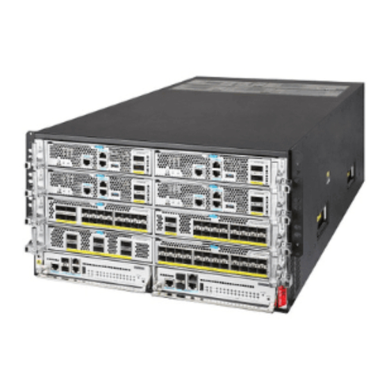
- Page 31 Appendix A Chassis views This document is applicable to H3C SecPath M9000-X multiservice security gateway series and H3C SecPath M9000-AI-X multiservice security gateway series. Table11-1 H3C SecPath M9000-X and M9000-AI-X multiservice security gateway series models Gateway series Model M9000-X06 M9000-X...
- Page 32 Figure11-2 Rear view (3) Power supply section (4) Fan tray section (5) Switching fabric module section Table11-2 Descriptions for the M9000-X06/M9000-AI-X06 sections Section Slots Remarks MPU section Slots 4 and 5 An interface switch module provides two slots Interface switch Slots 0 to 3 in which you can install firewall modules or module section...
- Page 33 M9000-X10/M9000-AI-X10 Figure11-3 Front view Slot 0 Slot 1 Slot 2 Slot 3 Slot 4 Slot 5 Slot 6 Slot 7 Slot 8 Slot 9 (1) MPU section (2) Interface switch module section Figure11-4 Rear view (3) Power supply section (4) Fan tray section (5) Switching fabric module section 11-3...
- Page 34 Table11-3 Descriptions for the M9000-X10/M9000-AI-X10 sections Section Slots Remarks MPU section Slots 0 and 1 • An interface switch module provides two slots in which you can install firewall modules and interface modules. • Interface switch Interface modules and firewall modules Slots 2 to 9 module section are not hot swappable.
Need help?
Do you have a question about the SecPath M9000-X and is the answer not in the manual?
Questions and answers