
Related Manuals for H3C WSG1808X-PWR


Summary of Contents for H3C WSG1808X-PWR
- Page 1 H3C WSG1808X-PWR Wireless Integrated Services Gateway Installation Guide New H3C Technologies Co., Ltd. http://www.h3c.com Document version: 5W101-20240408...
- Page 2 The information in this document is subject to change without notice. All contents in this document, including statements, information, and recommendations, are believed to be accurate, but they are presented without warranty of any kind, express or implied. H3C shall not be liable for technical or editorial errors or omissions contained herein.
- Page 3 Preface This installation guide describes the installation procedures for the WSG1808X-PWR wireless integrated services gateway, including preparing for installation, installing the wireless integrated services gateway, and accessing the wireless integrated services gateway. This preface includes the following topics about the documentation: •...
- Page 4 It is normal that the port numbers, sample output, screenshots, and other information in the examples differ from what you have on your device. Documentation feedback You can e-mail your comments about product documentation to info@h3c.com. Your comments or suggestions would be highly appreciated.
-
Page 5: Table Of Contents
Examining the installation site ···························································································································· 2 Temperature and humidity ························································································································· 2 Cleanliness ················································································································································· 2 ESD prevention ·········································································································································· 3 EMI ····························································································································································· 3 Lightning protection ···································································································································· 4 Installation accessories ······································································································································ 4 EWP-WSG1808X-PWR ····························································································································· 4 EWP-WSG1808X-PWR-JP ························································································································ 4 Installation tools ················································································································································· 5 Pre-installation checklist····································································································································· 5... -
Page 6: Preparing For Installation
Preparing for installation Safety recommendations To avoid any equipment damage or bodily injury, read the following safety recommendations before installation. Note that the recommendations do not cover every possible hazardous condition. Safety symbols When reading this document, note the following symbols: WARNING means an alert that calls attention to important information that if not understood or followed can result in personal injury. -
Page 7: Laser Safety
Laser safety WARNING! Do not stare into any open apertures of operating transceiver modules or optical fiber connectors. The laser light emitted from these apertures might hurt your eyes. CAUTION: • Before you remove the optical fiber connector from a fiber port, execute the shutdown command in interface view to shut down the port. -
Page 8: Esd Prevention
Substance Concentration limit (particles/m Dust particle diameter ≥ 5 µm To eliminate corrosion and premature aging of components, the equipment room must also meet limits on salts, acids, and sulfides, as shown in Table1-3. Table1-3 Harmful gas limits in an equipment room Max. -
Page 9: Lightning Protection
Make sure the grounding cable of the chassis is grounded reliably. • Make sure the grounding terminal of the AC power receptacle is grounded reliably. Installation accessories EWP-WSG1808X-PWR Figure1-1 Installation accessories EWP-WSG1808X-PWR-JP No power adapter is provided with the EWP-WSG1808X-PWR-JP. Purchase the EWPX100POE power adapter from H3C as required. -
Page 10: Installation Tools
Figure1-2 Installation accessories Installation tools No installation tools are provided with the device. Prepare installation tools as required. Figure1-3 Installation tools Pre-installation checklist Table1-4 Pre-installation checklist Item Requirements Result • There is a minimum clearance of 100 mm (3.94 in)) around the device for heat dissipation. - Page 11 Item Requirements Result components when you observe or move a removed interface module. • Put the removed interface modules away on an ESD workbench, with the PCB upward, or put them in ESD bags for future use. • Effective measures are taken for filtering interference from the power grid.
- Page 12 Contents Installing the device ······················································································· 1 Confirming installation preparations ··················································································································· 1 Installation flowchart··········································································································································· 1 Mounting the device on a workbench ················································································································ 2 Mounting the device on a wall ···························································································································· 2 Grounding the device ········································································································································· 5 Connecting Interface cables······························································································································· 6 Connecting the console cable ···················································································································· 6 Connecting Ethernet cables ·······················································································································...
-
Page 13: Installing The Device
WARNING! Keep the tamper-proof seal on a mounting screw on the chassis cover intact, and if you want to open the chassis, contact H3C Support for permission. Otherwise, H3C shall not be liable for any consequence caused thereby. Confirming installation preparations Before you install the device, verify that you have read "Preparing for installation"... -
Page 14: Mounting The Device On A Workbench
Mounting the device on a workbench CAUTION: Do not place heavy objects on the device. To mount the device on a workbench: Place the device upside down. Clean the recessed areas on the chassis bottom. Attach the four rubber feet to the recessed areas on the chassis bottom. Place the device on the workbench with the upside up. - Page 15 Figure2-3 Installation hole spacing Drill two holes with a diameter of 6 mm (0.24 in) and a depth of 30 mm (1.18 in) at the marked locations. Figure2-4 Drilling installation holes Insert an expansion anchor into each hole, and tap the expansion anchor with a rubber hammer until it is all flush with the wall surface.
- Page 16 Figure2-5 Hammering the expansion anchor into the wall Fasten the self-tapping screws to secure the expansion anchors to the wall. Figure2-6 Fastening self-tapping screws Align the holes on the rear of the device with the self-tapping screws. Hang the device on the self-tapping screws and then slide the device down to secure it to the wall.
-
Page 17: Grounding The Device
Figure2-7 Securing the device to the wall Grounding the device WARNING! • Correctly connecting the grounding cable is crucial to lightning protection and EMI protection. Before installing or using the device, connect the grounding cable for it correctly. • Connect the grounding cable to the grounding system in the equipment room. Do not connect it to a fire main or lightning rod. -
Page 18: Connecting Interface Cables
If earth is available at the installation site, you can ground the device with a grounding conductor buried in the earth. Hammer a 0.5 m (1.64 ft) or longer angle iron or steel tube into the earth to serve as a grounding conductor. - Page 19 CAUTION: • To connect a fiber port by using an optical fiber, first install a transceiver module in the port and then connect the optical fiber to the transceiver module. • Insert a dust cap into any open optical fiber connector and a dust plug into any open fiber port or transceiver module port to protect them from contamination and ESD damage.
-
Page 20: Connecting The Power Cord
The Ethernet cables, optical fibers, and power cord are connected correctly. Powering on the device NOTE: The following procedure uses the EWP-WSG1808X-PWR access controller as an example. Power on the device. The device initializes its memory and runs the BootWare. The following information appears on the terminal screen: System is starting... - Page 21 Loading file flash:/boot.bin....Done. Image file flash:/boot.bin is self-decompressing..Done. System image is starting... Cryptographic algorithms tests passed. Line con0 is available. Press ENTER to get started. Press Enter at the prompt, and you can configure the device when the prompt <H3C> appears.
- Page 22 Contents Log in to the device ························································································ 1 Log in through Telnet or SSH····························································································································· 1 Configure Telnet login ································································································································ 1 Configure SSH login ··································································································································· 1 Log in through the console port·························································································································· 1 About this task ············································································································································ 1 Prerequisites ·············································································································································· 1 Configure terminal parameters ···················································································································...
- Page 23 Log in to the device You can log in to a device through Telnet, SSH, or the Console port, or from the Web interface. • Telnet/SSH login—Log in to the device through a remote connection to configure or manage the device. •...
- Page 24 • When you disconnect a PC from the device, first remove the RJ-45 connector and then remove the DB-9 connector as a best practice. • If the PC does not have an RS-232 interface but has an USB port, use a USB-to-RS-232 adapter to connect the console cable.
- Page 25 Procedure To log in to the device from the Web interface through a wired connection: Visit the default IP address 192.168.0.100 to access the local Web interface. Enter the default username and password, and then click the login button. For security purposes, change the login password as prompted.
- Page 26 Contents Hardware management and maintenance ····················································· 1 Displaying hardware information about the device ···························································································· 1 Displaying software and hardware version information about the device ·················································· 1 Displaying the operational statistics about the device················································································ 1 Displaying information about the device ···································································································· 3 Displaying electrical label information for the device ·················································································...
-
Page 27: Hardware Management And Maintenance
<H3C> display version H3C Comware Software, Version 7.1.064, ESS 5626 Copyright (c) 2004-2023 New H3C Technologies Co., Ltd. All rights reserved. H3C WSG1808X-PWR uptime is 0 weeks, 0 days, 0 hours, 1 minute Last reboot reason : Power on Boot image: flash:/boot.bin Boot image version: 7.1.064, ESS 5626... - Page 28 ===============display version=============== H3C Comware Software, Version 7.1.064, ESS 5626 Copyright (c) 2004-2023 New H3C Technologies Co., Ltd. All rights reserved. H3C WSG1808X-PWR uptime is 0 weeks, 0 days, 0 hours, 19 minutes Last reboot reason : Power on Boot image: flash:/boot.bin Boot image version: 7.1.064, ESS 5626...
-
Page 29: Displaying Information About The Device
An electrical label is a profile of a device. It contains the permanent configuration, including the serial number, manufacturing date, MAC address, and vendor name. Use the command to display the electrical label information for the display device manuinfo device. <H3C> display device manuinfo DEVICE_NAME:WSG1808X-PWR DEVICE_SERIAL_NUMBER:219801A5NNAAAAA0928 MAC_ADDRESS:54C6-FFC4-DBA0 MANUFACTURING_DATE:2023-01-31 VENDOR_NAME:H3C... -
Page 30: Displaying The Cpu Usage Of The Device
Displaying the CPU usage of the device Use the command to display the CPU usage statistics for the device. display cpu-usage <H3C> display cpu-usage Unit CPU usage: 1% in last 5 seconds 1% in last 1 minute 2% in last 5 minutes... -
Page 31: Rebooting The Device
Field Description Mem:Cached, which indicates the physical memory available for applications. Swap Swap memory. Rebooting the device To reboot the device, use one of the following methods: • Reboot the device at the CLI. You can remotely reboot the device in either of the following ways: Reboot the device immediately by using the command. - Page 33 Contents Troubleshooting ····························································································· 1 Power supply failure ··········································································································································· 1 Symptom ···················································································································································· 1 Solution ······················································································································································ 1 No display or garbled display on the configuration terminal ·············································································· 1 Symptom ···················································································································································· 1 Solution ······················································································································································ 1 Software loading failure······································································································································ 2 Symptom ···················································································································································· 2 Solution ······················································································································································ 2...
- Page 34 Troubleshooting Power supply failure Symptom The device cannot be powered on. The system status LED (SYS) is off. Solution To resolve the issue: Verify that the power source is as required. Verify that the power cord is connected securely. Verify that the power cord is in good condition. If the issue persists, contact Technical Support.
- Page 35 Software loading failure Symptom The device fails in software loading. Solution To resolve the issue: Verify that the physical ports are connected securely and correctly. If a port is not connected securely, reconnect the port and make sure the connections are correct. View the software loading process displayed on the HyperTerminal to check for errors.
- Page 36 Contents Appendix A Chassis views and technical specifications ································ 1 Chassis views ···················································································································································· 1 Interface arrangement ········································································································································ 1 Technical specifications ····································································································································· 1...
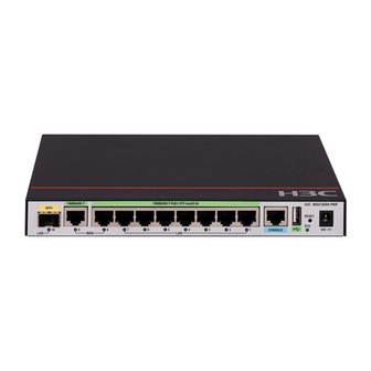
- Page 37 Appendix A Chassis views and technical specifications Chassis views Figure5-1 Front view (1) SFP+ port (2) 1000BASE-T Ethernet port WAN 9 (3) 1000BASE-T-PoE+ autosensing Ethernet port (4) 1000BASE-T-PoE+ autosensing Ethernet ports WAN 8 LAN 1 to LAN 7 (5) Console port (6) USB port (7) Reset button (RESET) (8) 54V power input receptacle...
- Page 38 Item Specification • 1 × 1000BASE-T Ethernet copper port: WAN 9 • 8 × 1000BASE-T-PoE+ autosensing Ethernet copper GE port ports (LAN 1 to LAN 7 and WAN 8): The ports can provide PoE+ power. Each can provide a maximum PoE+ power of 30 W.
- Page 39 Contents Appendix B LEDs·························································································· 1 LEDs ·································································································································································· 1 LED description ·················································································································································· 1...
- Page 40 Appendix B LEDs LEDs During startup of the device, the status LEDs for ports 1 to 4 being on for a while indicates that the chip is in self-test state. Figure1-1 LEDs (1) SFP+ port LED (2) 1000BASE-T port LED (3) and (4) 1000BASE-T-PoE+ autosensing port (5) System status LED (SYS) LEDs...
- Page 41 Mark Status Description Mbps or 10 Gbps. No link is present on the port.
- Page 42 Contents Appendix C Optional transceiver modules ···················································· 1 Views·································································································································································· 1 Specifications ····················································································································································· 1...
- Page 43 Appendix C Optional transceiver modules Views You must use an SFP or SFP+ transceiver module and optical fiber with an LC connector to connect the fiber port on the device. Figure7-1 SFP transceiver module Figure7-2 SFP+ transceiver module Figure7-3 Optical fibers with LC connectors (1) LC connector (2) Optical fiber Specifications...
- Page 44 The H3C transceiver modules are subject to change over time. For the most recent list of H3C transceiver modules, contact Technical Support or marketing staff. Table7-1 SFP-GE-SX-MM850-A transceiver module specifications Item SFP-GE-SX-MM850-A Central wavelength 850 nm Max transmission distance 550 m (1804.46 ft)
- Page 45 Table7-4 SFP-XG-SX-MM850-E specifications Item SFP-XG-SX-MM850-E Central wavelength 850 nm Max transmission distance 300 m (984.25 ft) Data rate 10.31 Gb/s Connector type Duplex LC connector Fiber mode 50 μm Fiber diameter Output power –7.3 to –1 dBm ≤ –9.9 dBm Receiver sensitivity ≤...
Need help?
Do you have a question about the WSG1808X-PWR and is the answer not in the manual?
Questions and answers