
Subscribe to Our Youtube Channel
Related Manuals for Wexiodisk WD-B 500


Summary of Contents for Wexiodisk WD-B 500
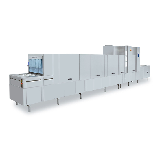
- Page 1 FLIGHT-TYPE DISHWASHER WD-B 500 - WD-B 900 (translation of the original documentation) Installation and user manual S/N: Valid from: 2012-08-01 Rev.: 4.0...
-
Page 3: Table Of Contents
Rev. 4.0 (201208) WD-B 500 - WD-B 900 1. General information ................. 1 1.1 Symbols used in this manual ................1 1.2 Symbols on the dishwasher ................1 1.2.1 Machine marking ..................2 1.3 RoHS compatible ..................... 2 1.4 Checking that the machine and the manual correspond ........2 2. - Page 4 3.9 Filling booster heater 3 with R/O water (option) ..........20 3.10 Adjusting the air flow in the drying zone ............21 3.10.1 WD-B 500, electrically heated, one drying zone ........22 3.10.2 WD-B 600, electrically heated, one drying zone ........22 3.10.3 WD-B 700, electrically heated, one drying zone ........
-
Page 5: General Information
WD-B 500 - WD-B 900 Rev. 4.0 (201208) General information 1. General information Read the instructions in this manual carefully as they contain important informa- tion regarding the correct, effective and safe installation, use and servicing of the dishwasher. Keep this manual in a safe place so that it can be used by other operators of the dishwasher. -
Page 6: Machine Marking
WD-B 500 - WD-B 900 Rev. 4.0 (201208) General information 1.2.1 Machine marking The rating plates are located at the bottom of the outfeed side and in the electrical cabinet. The technical information on the plates is also included on the machine's wiring diagram. -
Page 7: Safety Instructions
WD-B 500 - WD-B 900 Rev. 4.0 (201208) Safety instructions 2. Safety instructions 2.1 General information The machine is CE marked, which means that it complies with the requirements of the EU machinery directive with regard to product safety. Product safety means that the design of the machine will prevent personal injury or damage to property. -
Page 8: Detergent And Drying Agent
WD-B 500 - WD-B 900 Rev. 4.0 (201208) Safety instructions 2.4 Detergent and drying agent Only detergent and drying agent intended for industrial dishwashing machines must be used. Ordinary washing-up liquid must not be used in the machine or for pre-treating items (soaking, pre-washing, etc.). -
Page 9: Cleaning
WD-B 500 - WD-B 900 Rev. 4.0 (201208) Safety instructions 2.7 Cleaning The water in the chemical wash tank is at a temperature of approx. 60° C and con- tains detergent. Be careful when emptying and cleaning the tanks. Use protective gloves. -
Page 10: Installation
WD-B 500 - WD-B 900 Rev. 4.0 (201208) Installation 3. Installation 3.1 General information The machine must be installed by authorised personnel only. Read these instructions carefully, as they contain important information regarding the correct installation method. The instructions should be used together with the machine drawing, wiring dia- gram and flow diagram. -
Page 11: Space For Servicing
WD-B 500 - WD-B 900 Rev. 4.0 (201208) Installation 3.2.4 Space for servicing The area above the machine must not contain any equipment which could pre- vent the fitting, servicing and replacement of parts. A free height of at least 2.8 metres is required in order to remove the inspection doors. -
Page 12: Marking Of Sections
WD-B 500 - WD-B 900 Rev. 4.0 (201208) Installation 3.4 Marking of sections The machine is normally divided into two sections. In some cases the machine can be delivered in more than two sections. The installation instructions describe the assembly of a machine that has been split into two sections. Regardless of the number of sections, the assembly of all sections is undertaken in the same way. -
Page 13: Unpacking
WD-B 500 - WD-B 900 Rev. 4.0 (201208) Installation 3.5 Unpacking • Check against the delivery note that all the units have been delivered. • Remove the packaging, but leave the pallet and any transport supports in place. • Inspect the machine for any transport damage. -
Page 14: Installation
WD-B 500 - WD-B 900 Rev. 4.0 (201208) Installation 3.6 Installation 3.6.1 General information Parts which must be assembled are prepacked inside each machine section to- gether with the necessary bolts, nuts, etc. Remove all lower cover plates (5). The final position of the machine is either free-standing in the room or placed with the back against a wall. -
Page 15: Assembly Of Sections
WD-B 500 - WD-B 900 Rev. 4.0 (201208) Installation 3.6.2 Assembly of sections • Remove any transport supports. • Place section 2 in the appropriate place at the right height. Check that the section is horizontal using a spirit level (on the tank body). Adjust the ma- chine using the legs. - Page 16 WD-B 500 - WD-B 900 Rev. 4.0 (201208) Installation Skarv Locking the stand A=Leg B=Joint on the stand C=Stand D=M6x10 Bolts E=Joining tube Assembly of clamp strips and upper cover plates • When the sections have been fitted together, the clamp strips (A) should be fitted inside the joint.
-
Page 17: Pipes
WD-B 500 - WD-B 900 Rev. 4.0 (201208) Installation 3.6.3 Pipes Fit together all pipes for water, steam, condensation water and waste (pipe for steam and condensation water on steam-heated machines only). The pipes are split at the section join. The necessary parts for joining the pipes together are fit- ted to the pipes at the joint. -
Page 18: Other Assembly
WD-B 500 - WD-B 900 Rev. 4.0 (201208) Installation 3.6.5 Other assembly • Fit the chain (4) to the drive motor. • Pull out and connect the electric cables for the pumps and other compo- nents. The cables are located at the section joint. -
Page 19: Connections
WD-B 500 - WD-B 900 Rev. 4.0 (201208) Installation 3.7 Connections The picture below shows a machine with the feed direction from right to left. The length of the infeed and outfeed and the number of washing and drying zones vary depending on the size of the machine. -
Page 20: Water Connection
WD-B 500 - WD-B 900 Rev. 4.0 (201208) Installation 3.7.1 Water connection The machine is supplied as standard without stopcocks for the water supply. Stopcocks must be installed on incoming pipes. It is important that the water supply has sufficient pressure to ensure the correct flow of water to the machine. -
Page 21: Drain Connection
WD-B 500 - WD-B 900 Rev. 4.0 (201208) Installation 3.7.4 Drain connection The drain is connected using a 50mm metal tube which tolerates mechanical im- pacts. The drain must run to a floor drain, where its opening must be above the water level. -
Page 22: Electrical Connection
WD-B 500 - WD-B 900 Rev. 4.0 (201208) Installation 3.7.7 Electrical connection This symbol on a machine component warns of the presence of electrical equip- ment. The component may only be removed by a qualified electrician. The ma- chine is sensitive to electrostatic discharge (ESD), and a static electricity bracelet must therefore be used when handling the electronics. -
Page 23: Checking And Setting The Final Rinse Flow
WD-B 500 - WD-B 900 Rev. 4.0 (201208) Installation 3.8 Checking and setting the final rinse flow WDB_09 Control panel functions for checking the final rinse flow Button for the feed Button for the diagnostics function Button for switching between diagnostic messages... -
Page 24: Filling Booster Heater 3 With R/O Water (Option)
WD-B 500 - WD-B 900 Rev. 4.0 (201208) Installation 3.9 Filling booster heater 3 with R/O water (option) WDB_15 Functions on the control panel and circuit board for activating and using the diag- nostics function Button for activating the diagnostics function. -
Page 25: Adjusting The Air Flow In The Drying Zone
WD-B 500 - WD-B 900 Rev. 4.0 (201208) Installation 3.10 Adjusting the air flow in the drying zone The positioning of the spread plates, guide plates etc. which control the air flow will depend on a variety of factors, such as the size of the machine, whether it is electrically or steam heated, the temperature and ventilation in the dishwashing room etc. -
Page 26: Wd-B 500, Electrically Heated, One Drying Zone
WD-B 500 - WD-B 900 Rev. 4.0 (201208) Installation 3.10.1 WD-B 500, electrically heated, one drying zone • Damper (I) half open. • Damper plate (B) fully open towards final rinse zone. • Spreader plate (E) pushed towards infeed. 2 mm gap between (E) and (D). -
Page 27: Cleaning The Exterior
WD-B 500 - WD-B 900 Rev. 4.0 (201208) Installation 3.11 Cleaning the exterior Remove the protective plastic from the machine and polish it with a suitable clean- ing material for stainless steel plate. Use a suitable solvent to remove any residual adhesive from the plastic. Rub with a forwards and backwards movement in the polishing direction of the plate. -
Page 28: Trial Run
WD-B 500 - WD-B 900 Rev. 4.0 (201208) Installation 3.12 Trial run Prepare the machine for trial operation by following the INSTRUCTIONS FOR USE. The instructions describe the measures that must be taken to prepare the machine for operation. 3.12.1 Start-up schedule This should be completed and signed by the customer on start-up. - Page 29 WD-B 500 - WD-B 900 Rev. 4.0 (201208) Installation Read the installation and user manuals carefully. Then check the following points: 1. Check: • Water and drain connections • That the machine is evenly balanced • Detergent and drying agent •...
-
Page 30: Technical Documentation
WD-B 500 - WD-B 900 Rev. 4.0 (201208) Installation 3.13 Technical documentation To ensure that the machine is used correctly, it is essential that the documenta- tion supplied with the machine is made available to the staff who will be using the machine. -
Page 31: Instructions For Use
WD-B 500 - WD-B 900 Rev. 4.0 (201208) Instructions for use 4. Instructions for use All staff using the machine must be given training in how the machine works by the person responsible for staff safety. The dishwasher should not be used by anyone suffering from a physical or mental illness. -
Page 32: Preparations
WD-B 500 - WD-B 900 Rev. 4.0 (201208) Instructions for use 4.1 Preparations 4.1.1 The machine's design WDB_10_Q Control panel 15 16 WDB_11 The picture shows a machine with pre-wash, intermediate rinse (option) and two chemical wash tanks. The machines can be supplied with more or fewer washing... - Page 33 WD-B 500 - WD-B 900 Rev. 4.0 (201208) Instructions for use Display Symbol for contact time (washing time) Symbol for washing Knob for selecting contact time (washing time) LED for indication of alarms. If the LED flashes, the alarm can be reset by pressing button (11).
-
Page 34: Preparations Before Filling
WD-B 500 - WD-B 900 Rev. 4.0 (201208) Instructions for use 4.1.2 Preparations before filling Check: • that the machine has been cleaned and that the stopcocks for the water are open. • the amount of detergent and drying agent. -
Page 35: Using The Machine
WD-B 500 - WD-B 900 Rev. 4.0 (201208) Instructions for use 4.2 Using the machine 4.2.1 Washing Setting for normal or heavily soiled loads (option) As additional equipment, the machine can be fitted with a function for washing normal or heavily soiled loads. If there is an option to change the rinse pressure, the machine is fitted with a lever (22) next to the infeed. -
Page 36: Emergency Stop
WD-B 500 - WD-B 900 Rev. 4.0 (201208) Instructions for use Selecting the contact time / wash time When the machine's feed has started, a text message appears on the display in- dicating that the machine is ready to wash and giving a contact time in seconds. -
Page 37: Lights Which Indicate Alarms (Option)
WD-B 500 - WD-B 900 Rev. 4.0 (201208) Instructions for use 4.2.3 Lights which indicate alarms (option) The light bar (17) has flashing or non-flashing lights to indicate the following states: • Green non-flashing light=Machine in operation • Yellow flashing light=Alarm. Check the message on the control panel dis- play. -
Page 38: Daily Cleaning
WD-B 500 - WD-B 900 Rev. 4.0 (201208) Instructions for use 4.3.2 Daily cleaning Cleaning the inside • Switch the machine off by pressing button (12). • Empty the machine by turning the outlet seals (27) a quarter of a turn. - Page 39 WD-B 500 - WD-B 900 Rev. 4.0 (201208) Instructions for use Cleaning the exterior Wipe the outside of the machine with a soft, damp cloth. If detergent is used, it must not contain abrasives. Detergents containing abra- sives will damage the stainless steel panels.
-
Page 40: Cleaning And Checking Each Week Or As Required
WD-B 500 - WD-B 900 Rev. 4.0 (201208) Instructions for use 4.3.3 Cleaning and checking each week or as required Weekly cleaning should be more thorough than daily cleaning. In addition to the daily cleaning measures, follow these instructions: •... -
Page 41: Operating Problems
WD-B 500 - WD-B 900 Rev. 4.0 (201208) Instructions for use 4.3.4 Operating problems Error messages Machine faults and user faults are indicated with messages on the display (1). If an alarm occurs, LED (5) will light up or flash. If the LED flashes, the alarm can be reset by pressing button (11). - Page 42 WD-B 500 - WD-B 900 Rev. 4.0 (201208) Instructions for use Alarm texts Alarm text Cause Action (47) HACCP ALARM One of the pumps is not working. Reset the alarm using button (11). PUMP FUNCTIONALITY Contact service personnel. DEFECT The water level in one of the tanks is Close the outlet seals.
- Page 43 WD-B 500 - WD-B 900 Rev. 4.0 (201208) Instructions for use Alarm texts Alarm text Cause Action (39) OVER FLOW PIPE The level pipe is not sitting in place Check the position of the level pipe. NOT IN POSITION properly.
- Page 44 WD-B 500 - WD-B 900 Rev. 4.0 (201208) Instructions for use Alarm texts Alarm text Cause Action (62) The temperature in tank 3 is too low. Reset the alarm using button (11). LOW TEMPERATURE Contact service personnel. IN TANK 3...
- Page 45 WD-B 500 - WD-B 900 Rev. 4.0 (201208) Instructions for use Troubleshooting In addition to the faults shown on the control panel, other faults can occur. The table below shows some faults which can be rectified by the operator. If the prob- lem persists, contact authorised service personnel.
- Page 46 WD-B 500 - WD-B 900 Rev. 4.0 (201208) Instructions for use When you contact service personnel, you will need to provide the following infor- mation: • Machine model • Machine serial number and installation date • A brief description of the problem •...
-
Page 47: Technical Specifications
Booster heater 1, final rinse (kW) Booster heater 2, final rinse (kW) Tank heater, chemical wash 1 (kW), (WD-B 500 - WD-B 600) Tank heater, chemical wash 1 (kW), (WD-B 700 - WD-B 900) Tank heater, chemical wash 2 (kW), (WD-B 700 - WD-B 900) - Page 48 Cold water consumption, normal final rinse (litres/hour), (WD-B 900) 210-260 Steam consumption at 150-250 kPa (kg/hour), (WD-B 500 - WD-B 600) * Steam consumption at 50-140 kPa (kg/hour), (WD-B 500 - WD-B 600) * Steam consumption at 150-250 kPa (kg/hour), (WD-B 700 - WD-B 800) *...
- Page 49 Main fuse 400 V 3N~ (A), (WD-B 700 - WD-B 800) ** Main fuse 400 V 3N~ (A), (WD-B 900) ** Max. connection area 400 V 3N~ (L1-L3, N, PE) Cu (mm²), (WD-B 500 - WD-B 800) Max. connection area 400 V 3N~ (L1-L3, N, PE) Cu (mm²), (WD-B 900) Steam connection (external thread), (WD-B 500 - WD-B 600) R1"...
- Page 50 Water capacity, flow (litres/min.) Floor drain, capacity (litres/sec) Heat load to the room, sensible (kW) (WD-B 500 - WD-B 600) Heat load to the room, sensible (kW) (WD-B 700 - WD-B 800) Heat load to the room, sensible (kW) (WD-B 900)
Need help?
Do you have a question about the WD-B 500 and is the answer not in the manual?
Questions and answers