
Subscribe to Our Youtube Channel
Related Manuals for Kongsberg HiPAP 352P


Summary of Contents for Kongsberg HiPAP 352P
- Page 1 HiPAP 352P High Precision Acoustic Positioning system Instruction manual 422971/C April 2023 © Kongsberg Maritime AS...
- Page 2 Kongsberg Maritime disclaims any responsibility for damage or injury caused by improper installation, use or maintenance of the equipment. Disclaimer Kongsberg Maritime AS endeavours to ensure that all information in this document is correct and fairly stated, but does not accept liability for any errors or omissions. Support information If you require maintenance or repair, contact Kongsberg Maritime’s support organisation.
-
Page 3: Table Of Contents
Converting from fibre optical to electrical signal ............16 CABLING ................17 Cable plan ........................18 List of cables ........................19 Installing the HiPAP 352P cables ..................20 Installing the system cables ..................20 Connecting the Responder Driver Unit to the responder ........21 OPERATING PROCEDURES ............. 22 MAINTENANCE .............. - Page 4 HiPAP 352P HiPAP 352P-MGC-x spare parts ..................29 HiPAP interface unit spare part..................29 Repeater unit spare part ....................29 Responder driver unit spare part ..................30 TECHNICAL SPECIFICATIONS..........31 Performance specifications ....................32 Weights and outline dimensions ..................33 Power specifications......................33 Environmental specifications ...................34 DRAWING FILE..............36 Computer dimensions ......................37...
-
Page 5: About This Manual
Microsoft Corporation in the United States and other countries. HiPAP ® is a registered trademark of Kongsberg Maritime AS in Norway and other countries. ® cNODE is a registered trademark of Kongsberg Maritime AS in Norway and other countries. -
Page 6: Hipap 352P
HiPAP 352P Instruction manual HiPAP 352P Topics System description, page 7 System diagram, page 8 Main system units, page 9 Scope of supply, page 11 General supply conditions, page 12 Support information, page 13 422971/C... -
Page 7: System Description
HiPAP 352P System description The HiPAP 352P is a portable system designed for tracking ROV’s, tow fish, divers and other subsea objects at several thousand metres range. The HiPAP 352P systems calculates the accurate positions of subsea objects such as Remotely Operated Vehicles (ROVs), Autonomous Underwater Vehicles (AUV’s),... -
Page 8: System Diagram
HiPAP 352P Instruction manual System diagram The system diagram identifies the main components of a basic HiPAP 352P system. Only the main connections between the units are shown. Laptop computer Stationary computer Ethernet switch Responder Driver Unit Interface unit Repeater unit... -
Page 9: Main System Units
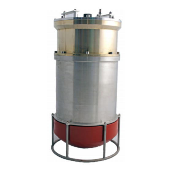
HiPAP 352P Main system units Transducer description The transducer converts the electric energy generated by the transmitter circuitry to physical vibrations. These vibrations alter the water pressure, and create an acoustic pulse that is sent into the water. The transducer integrates... -
Page 10: Hipap Interface Unit Description
HiPAP 352P Instruction manual HiPAP interface unit description The HiPAP interface unit connects the HiPAP transducer and the APOS operator station. The HiPAP interface unit includes a power supply that also powers the transducer. It connects to the transducer, the computer ( or a switch) and optionally to a responder. -
Page 11: Repeater Unit (Optional)
Scope of supply The main units you need are provided with the standard delivery. When you unpack the parts provided with the HiPAP 352P system delivery, make sure that the following items are included. • Transducer •... -
Page 12: General Supply Conditions
• The period of time between commissioning and the final acceptance of the equipment by the end user or owner Unless other arrangements have been made in the contract, the Kongsberg HiPAP 352P warranty period (as specified in the contract) begins when the acceptance documents have been signed. -
Page 13: Support Information
Support information Should you need technical support for your HiPAP 352P system you must contact a Kongsberg Maritime office. A list of all our offices is available on our website. You can also contact our main support office in Norway. -
Page 14: Installation
HiPAP 352P Instruction manual Installation Topics Installing the transducer, page 15 Installing the repeater unit, page 15 Installing the Responder Driver Unit, page 15 Converting from fibre optical to electrical signal, page 16 422971/C... -
Page 15: Installing The Transducer
Installation Installing the transducer The cabling must be done before installing the transducer. Context The transducer is mounted on the ship’s arrangement for the transducer. This may be on a pole lowered through a moon pool or a hull unit. The location of the transducer arrangement must be as far away as possible from thrusters, aerated water, noise sources or other equipment sensitive to acoustic noise in the water. -
Page 16: Converting From Fibre Optical To Electrical Signal
HiPAP 352P Instruction manual Procedure Open the unit by removing the four screws that secures the lid. Lift off the lid and see the four mounting holes, one in each corner. Mount the responder driver unit where suitable. The mounting screws with nuts and washers are delivered with the unit. -
Page 17: Cabling
Cabling Cabling Topics Cable plan, page 18 List of cables, page 19 Installing the HiPAP 352P cables, page 20 422971/C... -
Page 18: Cable Plan
HiPAP 352P Instruction manual Cable plan The cables are part of the delivery with the main units. Laptop computer Stationary computer Ethernet switch Responder Driver Unit Interface unit Repeater unit Transducer 422971/C... -
Page 19: List Of Cables
Cabling List of cables A set of cables is required to connect the system units to each other, and to the relevant power source(s). Cable Type From/To Transducer cable From Interface Unit to Transducer or Repeater Ethernet cable From interface unit to Ethernet switch/ From computer to interface unit AC Power cable... -
Page 20: Installing The Hipap 352P Cables
HiPAP 352P Instruction manual Installing the HiPAP 352P cables Installing the system cables To ensure correct use of cables and connectors, lubrication procedure and proper cable handling must be followed. Prerequisites This procedure includes all optional units. Use a repeater unit to amplify the signals when the transducer cable has to be longer than 70 metres. -
Page 21: Connecting The Responder Driver Unit To The Responder
Cabling 19 Connect the cable from the Responder Driver Unit to the interface unit. (C19) Connecting the Responder Driver Unit to the responder The Responder Driver Unit provides responder trigger signals to responders. These cables must be provided by the installation shipyard. Prerequisites The signal cables to the responder consists of 2 dsub connectors for electrical signals for responders 1–4 and four connectors for fibre optic connection to responders 5–8. -
Page 22: Operating Procedures
HiPAP 352P Instruction manual Operating procedures See APOS online help. 422971/C... -
Page 23: Maintenance
Maintenance Maintenance Topics Preventive maintenance schedule, page 24 Inspecting and cleaning the transducer, page 24 Lubricating and mating the underwater connectors, page 25 Creating a backup, page 26 422971/C... -
Page 24: Preventive Maintenance Schedule
HiPAP 352P Instruction manual Preventive maintenance schedule In order to secure a long and trouble-free operation of the HiPAP 352P system, certain specific preventive maintenance tasks must be done. The tasks are organized in a preventive maintenance schedule. • Actions to be taken after every use –... -
Page 25: Lubricating And Mating The Underwater Connectors
Maintenance Lubricating and mating the underwater connectors The underwater connectors must be lubricated before mating. Context Recommended amount of grease Procedure Remove old grease and any accumulated sand or mud, and clean the connector using isopropyl alcohol. Apply a layer of Parker Super O-Lube or Molykote 44M grease on the female connector corresponding to a minimum of 1/10 of the socket. -
Page 26: Creating A Backup
HiPAP 352P Instruction manual Creating a backup For backup procedures, refer to the backup files document, doc. no. 476331. This is a separate manual supplied with the system delivery. Take a backup of all operator stations at regular intervals (1-3 months), and every time major changes have been performed in the configuration and/or user settings. -
Page 27: Spare Parts
Spare parts Topics Portable operator station spare part, page 28 Operator station spare part, page 28 HiPAP 352P-H/5 spare parts, page 28 HiPAP 352P-MGC-x spare parts, page 29 HiPAP interface unit spare part, page 29 Repeater unit spare part, page 29... -
Page 28: Portable Operator Station Spare Part
HiPAP 352P Instruction manual Portable operator station spare part • : Portable operator station spare part Part name • : 448755 Part number Operator station spare part • : Operator station spare part Part name • : 472733 Part number HiPAP 352P-H/5 spare parts •... -
Page 29: Hipap 352P-Mgc-X Spare Parts
Spare parts HiPAP 352P-MGC-x spare parts • : HiPAP 352P-MGC-R2 Part name • : 467638 Part number • : HiPAP 352P-MGC-R3 Part name • : 422584 Part number HiPAP interface unit spare part • : HiPAP interface unit spare part Part name •... -
Page 30: Responder Driver Unit Spare Part
HiPAP 352P Instruction manual Responder driver unit spare part • : Responder driver unit spare part Part name • : 321990 Part number The spare part kit consists of: • Responder Driver Unit • AC/DC Power supply • Trigger cable •... -
Page 31: Technical Specifications
Technical specifications Technical specifications Topics Performance specifications, page 32 Weights and outline dimensions, page 33 Power specifications, page 33 Environmental specifications, page 34 422971/C... -
Page 32: Performance Specifications
HiPAP 352P Instruction manual Performance specifications These performance specifications summarize the main functional and operational characteristics of the system. HiPAP 352P- HiPAP 352P- HiPAP 352P-H HiPAP 352P-5 MGC-R2 MGC-R3 0.05 0.02 0.02 0.01 Motion sensor [°] Range ±180° Range ±180°... -
Page 33: Weights And Outline Dimensions
Technical specifications For 352P-H – See Kongsberg MRU H specification. For 352P-5 – See Kongsberg MRU 5 specification. Weights and outline dimensions These weights and outline dimension characteristics summarize the physical properties of the system. Transducer Model Diameter Height Weight... -
Page 34: Environmental Specifications
HiPAP 352P Instruction manual Laptop computer • : HP ProBook 640G8 Make and model • : 100/240 VAC, 50 to 60 Hz, autosensing Voltage requirement • : 1.7 A Normal current draw Interface unit The interface unit powers the transducer and the repeater unit. - Page 35 Technical specifications Stationary computer • : 0 to +55 °C Operating temperature • : -20 to 70 °C Storage temperature • : 5 to 95% relative, non-condensing Relative humidity Laptop computer • : 5 to 35 °C Operating temperature • : -20 to 70 °C Storage temperature •...
-
Page 36: Drawing File
Drawing file Topics Computer dimensions, page 37 Installing the transducer, page 38 HiPAP 352P -H/5 dimensions, page 39 HiPAP 352P -MGC-x dimensions, page 40 Interface unit dimensions, page 41 Repeater unit dimensions, page 42 Responder Driver Unit dimensions, page 43... -
Page 37: Computer Dimensions
Drawing file Computer dimensions 422971/C... -
Page 38: Installing The Transducer
HiPAP 352P Instruction manual Installing the transducer 422971/C... -
Page 39: Hipap 352P -H/5 Dimensions
Drawing file HiPAP 352P -H/5 dimensions 422971/C... -
Page 40: Hipap 352P -Mgc-X Dimensions
HiPAP 352P Instruction manual HiPAP 352P -MGC-x dimensions 422971/C... -
Page 41: Interface Unit Dimensions
Drawing file Interface unit dimensions 422971/C... -
Page 42: Repeater Unit Dimensions
HiPAP 352P Instruction manual Repeater unit dimensions 422971/C... -
Page 43: Responder Driver Unit Dimensions
Drawing file Responder Driver Unit dimensions 422971/C... -
Page 44: Fibre To Responder Drive Converter, Wiring Diagram
HiPAP 352P Instruction manual Fibre to responder drive converter, wiring diagram 422971/C... - Page 46 HiPAP 352P Instruction manual Index HiPAP 352P system diagram..........8 about HiPAP interface unit document downloads ........5 introduction ..........10 online information ........5 overview ..........10 registered trademarks........5 purpose ............ 10 target audience ..........5 spare part..........29 this publication ..........
- Page 47 Index HiPAP interface unit........29 Support information ........13 system spare part..........28 description ..........7 performance diagram............. 8 specifications ..........32 system software power backup ............. 26 requirements ..........33 preventive maintenance ..........24 maintenance schedule ........24 target audience procedure this publication ..........
- Page 48 ©2023 Kongsberg Maritime...
Need help?
Do you have a question about the HiPAP 352P and is the answer not in the manual?
Questions and answers