Table of Contents
Advertisement
Quick Links
K8AV2-R / K8AV2-RL
Item Checkup ...................................................................................7
Chapter 1 Specification ............................................. 8
1-1 K8AV2-R / K8AV2-RL Mainboard Layout .......................... 9
1-2 Mainboard Specification Table ........................................... 10
1-3 Chipset System Block Diagram ............................................ 11
1-4 Mainboard Specifications .................................................... 12
1-4.1 CPU Socket ................................................................................... 12
1-4.2 System Chipsets ........................................................................... 12
1-4.3 Memory ......................................................................................... 12
1-4.4 Accelerated Graphics Port (AGP) Interface ........................... 12
1-4.5 Expansion Slots ............................................................................ 12
1-4.6 BIOS (Basic Input Output System) .......................................... 13
1-4.7 Multi-I/O Functions .................................................................... 13
1-4.8 SATA RAID Interface ................................................................. 13
1-4.9 Advanced System Power Management .................................... 14
1-4.10 Audio Codec on board .............................................................. 14
1-4.11 LAN on board (K8AV2-RL only) ............................................ 14
1-4.12 Hardware Monitor on board ................................................... 14
1-4.13 Smart Card Reader On Board ................................................ 14
1-4.14 Form Factor ................................................................................ 14
Chapter 2 Hardware Setup ..................................... 16
2-1. CPU Installation with Socket 754 ...................................... 17
2-2 Memory Installation ............................................................. 18
2-2.1 To Install DDR SDRAM Module .............................................. 18
2-2.2 To Remove a DIMM .................................................................... 18
2-3 AGP Slot Installation ............................................................ 19
2-4 IDE Connector Installation ................................................. 20
Contents
4
Advertisement
Table of Contents

Related Manuals for SOLTEK K8AV2-R


Summary of Contents for SOLTEK K8AV2-R
-
Page 1: Table Of Contents
K8AV2-R / K8AV2-RL Contents Item Checkup ...................7 Chapter 1 Specification ..........8 1-1 K8AV2-R / K8AV2-RL Mainboard Layout ......9 1-2 Mainboard Specification Table ........... 10 1-3 Chipset System Block Diagram ..........11 1-4 Mainboard Specifications ............ 12 1-4.1 CPU Socket ................... 12 1-4.2 System Chipsets ................ - Page 2 Contents 2-5 Floppy Drive Connector ( FDC ) Installation ....21 2-6 SATA RAID Connector Installation ........22 2-7 ATX Power Supply Installation .......... 23 2-8 Jumper Settings ..............24 2-8.1 How to tackle the Jumpers: ............25 2-8.2 JCLK1: CPU Clock Select ............25 2-8.3 JBAT1: Clear CMOS ..............
- Page 3 K8AV2-R / K8AV2-RL 3-6.2 VIA6183 LAN driver on Windows NT4.0 ....... 48 3-6.3 VIA6183 LAN driver on Windows ME / 2000 / XP ....49 3-7 SATA RAID Driver Setup ............ 50 Chapter 4 BIOS Setup ..........51 4-1 About BIOS Setup ..............52 4-2 To Run BIOS Setup ...............
-
Page 4: Item Checkup
Contents 5-0-1 Disk Array Interpretation ............84 5-0-2 Disk Array Member ..............84 5-0-3 Disk Array Types Supported by VT8237 ........ 84 5-1 First Step to Set Up SATA RAID System ......85 5-2 Enable SATA-RAID Interface with System BIOS ... 86 5-3 To Enter VIA Tech. -
Page 5: Chapter 1 Specification
K8AV2-R / K8AV2-RL Chapter 1 Specification Introduction This mainboard features an integration of the powerful AMD Athlon 64 processors and the North Bridge VIA K8T800 plus South Bridge VT8237, with which the whole system performance supports Hyper Transport Speed up to 800MHz. -
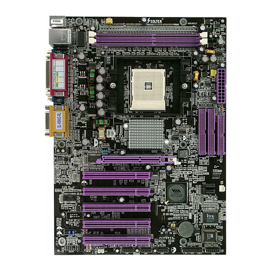
Page 6: K8Av2-R / K8Av2-Rl Mainboard Layout
Chapter 1 Specification 1-1 K8AV2-R / K8AV2-RL Mainboard Layout LAN Controller for K8AV2-RL only RJ45 Mouse JKB1 Fan1 (on top) DDR 400/333/266 MHz DIMM2 PS/2 K/B (underside) RJ45 (on top) USB1 DIMM1 USB0 Fan2 Main Power IDE1 IDE2 +12V Power... -
Page 7: Mainboard Specification Table
K8AV2-R / K8AV2-RL 1-2 Mainboard Specification Table K8AV2-R / K8AV2-RL Specifications and Features Socket 754 for AMD Athlon 64 CPUs K8T800, supporting up to 800MHz FSB North Bridge VT8237, SATA RAID controller South Bridge AWARD BIOS BIOS Supporting unbuffer DDR 400/333/266 SDRAM, up... -
Page 8: Chipset System Block Diagram
Chapter 1 Specification 1-3 Chipset System Block Diagram Socket 754 for AMD Athlon 64 CPUs VIA 800MHz Hyper Transport Bus DDR memory Interface System VIA K8T800 AGP 8X/4X AGP Slot Memory North Bridge DDR 266/ 333/400 SDRAM (unbuffer) Ultra V-Link 5 PCI Slots PCI Bus 2 IDE... -
Page 9: Mainboard Specifications
K8AV2-R / K8AV2-RL 1-4 Mainboard Specifications 1-4.1 CPU Socket CPU Socket 754 on board, supporting AMD Athlon 64 processors and implementing up to 800MHz Hyper Transport Speed (System Bus). 1-4.2 System Chipsets • North Bridge VIA K8T800 for managing and supporting up to 800MHz... -
Page 10: 1-4.6 Bios (Basic Input Output System)
Chapter 1 Specification 1-4.6 BIOS (Basic Input Output System) Flash Memory for easy upgrade, supporting BIOS Writing Protection, Year 2000 compliant, and supporting various hardware configuration during booting system (See Chapter 4 BIOS Setup): • Standard CMOS Features (Times, Date, Hard Disk Type etc.) •... -
Page 11: 1-4.9 Advanced System Power Management
• Hardware Monitor supported by LPC I/O IT8705F, to provide moni- toring and desktop management of hardware voltage, temperatures and fan speeds • Utility Software Soltek HM for displaying monitoring status is enclosed in Support CD for user’s installation. 1-4.13 Smart Card Reader On Board Connector “SCR 1”... - Page 12 Chapter 1 Specification M e m o M e m o...
-
Page 13: Chapter 2 Hardware Setup
K8AV2-R / K8AV2-RL Chapter 2 Hardware Setup To Get Things Ready for Hardware Setup ! 1. We recommend to install your CPU before any other components. For detailed installation instructions of processor, you can also refer to the pamphlet enclosed in your CPU package. -
Page 14: Cpu Installation With Socket 754
Chapter 2 Hardware Setup 2-1. CPU Installation with Socket 754 This series is built with CPU Socket 754 supporting the AMD CPUs Athlon 64: • Follow the steps described in this section to install CPU into the on- board Socket 754. •... -
Page 15: Memory Installation
K8AV2-R / K8AV2-RL 2-2 Memory Installation 2-2.1 To Install DDR SDRAM Module • This series supports up to 2GB DDR 400/333/266 SDRAM, with 2 DDR DIMM slots on board. Do not insert other type of modules into these slots. • DDR DIMM slot has 184-pins and one notch. Insert a DDR SDRAM vertically into the 184-pin slot with the notch-to-rib matching. -
Page 16: Agp Slot Installation
Chapter 2 Hardware Setup 2-3 AGP Slot Installation The AGP slot on board supports 1.5V AGP 8X/4X card only. A Rib is specifically added to the 8X/4X slot so as to match the AGP 8X/4X card. To insert a 3.3V AGP 2X card into the AGP 4X slot will damage the system chip and burn the 1.5V circuitry. -
Page 17: Ide Connector Installation
K8AV2-R / K8AV2-RL 2-4 IDE Connector Installation To install IDE Connector, you may connect the blue connector of IDE cable to the primary (IDE1) or secondary (IDE2) connector on board, and then connect the gray connector to your slave device and the black connector to your master device. -
Page 18: Floppy Drive Connector ( Fdc ) Installation
Chapter 2 Hardware Setup 2-5 Floppy Drive Connector ( FDC ) Installation To install FDC, you should connect the end of FDC cable with single connector to the board, and connect the other end with two connectors to the floppy drives. Mouse JKB1 Fan1... -
Page 19: Sata Raid Connector Installation
K8AV2-R / K8AV2-RL 2-6 SATA RAID Connector Installation 2 Serial ATA connectors are built on board, supported by the South Bridge VT8237 with SATA RAID interface. We can connect these two connectors to SATA Hard Disks and then configure these Hard Disks into SATA RAID Disks. -
Page 20: Atx Power Supply Installation
Chapter 2 Hardware Setup 2-7 ATX Power Supply Installation +12V Mouse JKB1 Fan1 (on top) DDR 400/333/266 MHz DIMM2 PS/2 K/B PWR OK (underside) RJ45 (on top) USB1 DIMM1 USB0 Fan2 Main PS ON# Power IDE1 IDE2 -12V +3.3V +3.3V +3.3V +12V Power K8T800... -
Page 21: Jumper Settings
K8AV2-R / K8AV2-RL 2-8 Jumper Settings The following diagrams show the locations and settings of jumper blocks on the mainboard. JKB1: KB/Mouse Wakeup 1-2 closed Enabled (default) 2-3 closed Disabled Mouse JKB1 Fan1 (on top) DDR 400/333/266 MHz DIMM2 PS/2 K/B... -
Page 22: 2-8.1 How To Tackle The Jumpers
Chapter 2 Hardware Setup 2-8.1 How to tackle the Jumpers: A 2-pin Jumper A 3-pin Jumper If a pin-header (of 2 or more pins) is designed in such a way that its pins can be closed or linked together to The conductor inside the cap set up a specific function, this header links two header-pins together. -
Page 23: 2-8.3 Jbat1: Clear Cmos
K8AV2-R / K8AV2-RL Note on CPU Overclocking: 1. If you have successfully booted system with or without CPU overclock, you still can do another CPU overclock in BIOS Setup. Please enter BIOS Setup, choose “Frequency/Voltage Control” menu, and enable the “Use CPU Linear Frequency”. Then configure the “CPU Clock”... -
Page 24: 2-8.4 Jkb1: Kb/Mouse Wake-Up
Chapter 2 Hardware Setup 2-8.4 JKB1: KB/Mouse Wake-up JKB1 is designed on board as a jumper to wake up system from sus- pend mode either with the the PS/2 keyboard/mouse. In addition, PS/ 2 Keyboard/Mouse Power-on function is also controlled by this jumper. Yet user should still enter “BIOS Setup”... -
Page 25: Other Connectors Configuration
K8AV2-R / K8AV2-RL 2-9 Other Connectors Configuration This section lists out all connectors configurations for users’ reference. 2-9.1 On-board FAN Connectors Void +12V Mouse JKB1 Fan1 (on top) DDR 400/333/266 MHz DIMM2 PS/2 K/B +12V (underside) RJ45 (on top) SENSOR... -
Page 26: 2-9.2 Usb Ports And Usb Pin-Headers
Chapter 2 Hardware Setup 2-9.2 USB Ports and USB Pin-headers This series provides two USB ports USB0 and USB1 on board sup- porting various USB devices. In addition, 3 USB pin-headers are added on board to provide expansion of 6 more USB ports by using 3 addi- tional USB Cables. -
Page 27: 2-9.3 Chassis Panel Connectors
K8AV2-R / K8AV2-RL 2-9.3 Chassis Panel Connectors G : COM 1 A : PS/2 MOUSE H : COM 2 B : RJ45 (K8AV2-RL) : Line Out / C : LPT1 PORT Front Speaker OUT D : Game/MIDI J : Line In /... -
Page 28: 2-9.5 Cd-Rom Audio Connectors (Cd-In1)
Chapter 2 Hardware Setup 2-9.5 CD-ROM Audio Connectors (CD-In1) CD-In1 is an audio connector connecting CD-ROM audio to mainboard. CD-ROM Audio Connector Line Line COM2 COM1 Game/MIDI Port LPT1 CD-In1 Pin Signal Pin 1 Left Channel Pin 2 Pin 3 Pin 4 Right Channel 2-9.6 Smart Card Reader Connector: SCR1... -
Page 29: 2-9.7 Connector Wol1: Wake On Lan
Back Panel Audio enabled. 2. To use this External Audio Connector, please open all pins of JAUD1 and connect it to the Front I/O Panel. (Front I/O Panel is an optional panel. It is available in Soltek Barebone system.) Mouse... -
Page 30: 2-9.9. Complex Pin-Header (Front Panel Connectors)
Chapter 2 Hardware Setup 2-9.9. Complex Pin-header (Front Panel Connectors) This complex Pin-header consists of the following connectors for vari- ous front panel supports. When you have fixed the mainboard to the case, join the connectors of this Complex Pin-header to the case Front Panel. -
Page 31: 2-9.10. Thermal Sensor
K8AV2-R / K8AV2-RL (2) IR Connector (Infrared Connector): Connection: Connected to Connector IR on board. Function: Supporting wireless transmitting and receiving module on board. (3) HDD LED Connector: Connection: Connected to HDD LED. Function: To supply power to HDD LED. -
Page 32: Chapter 3 Software Setup
Chapter 3 Software Setup Chapter 3 Software Setup Drivers, Utilities and Software Installation Support CD: This mainboard will be shipped with a Support CD which contains those necessary driver files, Application Softwares and some helpful utilities. It is a user-friendly, auto-run CD which will open itself up in a CD-ROM automatically. -
Page 33: To Open Up Support Cd
K8AV2-R / K8AV2-RL 3-1 To Open Up Support CD: 1. Please put the Support CD enclosed in your mainboard package into the CD-ROM drive. In a few seconds, the Main Menu will automatically appear, displaying the contents to be installed for this series: 2. -
Page 34: To Install Via 4-In-1 Drivers
Chapter 3 Software Setup 3-2 To Install VIA 4-IN-1 Drivers 1. Following the procedures of opening the Support CD, click to “ VIA 4- in-1 Drivers” to proceed. 3. “VIA Service Pack README” 2 . T h e V I A S e r v i c e P a c k screen will appear, please click InstallShield Wizard will pop up the “Yes”... - Page 35 K8AV2-R / K8AV2-RL 6. Select “Install VIA PCI IDE 7. Select “Install VIA AGP Driver” Driver” checkbox, then click the in turbo mode and press “Next” “Next” button to continue. button to continue. Next Next 8. After all these setup procedures have finished, you should restart your computer by clicking on “OK”...
-
Page 36: To Install Ac'97 Audio Driver
Chapter 3 Software Setup 3-3 To Install AC’97 Audio Driver VIA AC’97 Audio Codec VT1616 on board, AC’97 2.2 compatible, sup- porting 6 channel audio codec for PC multimedia systems. VIA AC’97 Audio Codec Driver is provided in Support CD for user’s installation. 3-3.1 Installation 1. -
Page 37: 3-3.2 To Verify 6-Channel Audio
K8AV2-R / K8AV2-RL 3-3.2 To verify 6-channel Audio After installation of AC’97 6-channel Codec, you must configure the 5.1 Speaker connection to enable the 6-channel audio. 1. Connect your on-board Audio Connector to your 6-channel speakers as depicted in the figure below:... - Page 38 Chapter 3 Software Setup 3. Again click “Advanced“ button to enter 6 channel configuration. 4. At the “Other Controls”, pick the item “Smart 5.1 Enable” to activiate 6 channel configuration. Then click “Close” to finish configuration.
-
Page 39: To Install Usb 2.0 Driver
K8AV2-R / K8AV2-RL 3-4 To Install USB 2.0 Driver VIA USB V2.0 is already integrated on board. Its 480Mb/s transfer rate supports operating systems Windows 98SE/Me/2000/XP. USB Driver installation procedures are of similar steps in these systems. Before installing VIA USB V2.0 Driver on Windows XP, users should install the latest Service Pack for Windows XP. - Page 40 Chapter 3 Software Setup 3. Instantly, next screen will pop up to prompt you to select component. Select “Install USB Driver” and click “Next” button to continue. Next 4. The USB 2.0 Setup Program will then guide you through the whole driver setup until the “Finish”...
-
Page 41: To Install Hardware Monitor Utility
K8AV2-R / K8AV2-RL 3-5 To Install Hardware Monitor Utility 3-5.1 Installation Hardware Monitor is built on this mainboard. Its installation is pro- grammed to a fully automated mode on Windows 9X/Me/NT4/2000/ XP. Users can follow the model installation below for its installation on various Windows System. -
Page 42: 3-5.2 Verification
Chapter 3 Software Setup 3-5.2 Verification 1. After installing Soltek Hardware Monitor, double click “SoltekHM” icon on the desktop to open the main window of the Soltek HM. Soltek Hardware Monitor Icon 2.Instantly, the pop-up screen will show all information about CPU Temperature, Fan Speed and various Voltages. -
Page 43: To Install Lan Driver (For K8Av2-Rl Only)
K8AV2-R / K8AV2-RL 3-6 To Install LAN Driver (for K8AV2-RL only) 3-6.1 VIA6183 LAN driver on Windows 98SE The VIA 6183 LAN driver contained in the Support CD supports VIA 6103 LAN chip. Yet it is not included in the Autorun Menu. To install VIA LAN driver on Windows 98SE, please follow the steps shown below: 1. - Page 44 Chapter 3 Software Setup 5. In the “Update device Driver Wizard” screen, click “Next” to continue until you see a dialog box asking you to “Specify a location” for the driver. You should now insert the Support CD into your CD-ROM. 6.
-
Page 45: 3-6.2 Via6183 Lan Driver On Windows Nt4.0
K8AV2-R / K8AV2-RL 3-6.2 VIA6183 LAN driver on Windows NT4.0 1. When you newly install Win NT4, the Setup program will ask you whether your computer will participate on a network. please check “Do not connect this computer to a network at this time” and continue with your installation. -
Page 46: 3-6.3 Via6183 Lan Driver On Windows Me / 2000 / Xp
Chapter 3 Software Setup 10. To verify that the onboard VIA LAN Controller has been set up in system, please click “Start”, then “Control Panel”, then “Network”. 11. In the “Network” screen, click the “Adapter” bar. You can now see the “VIA PCI 10/100Mb Fast Ethernet Adapter is already installed in system. -
Page 47: Sata Raid Driver Setup
K8AV2-R / K8AV2-RL 3-7 SATA RAID Driver Setup 1. 2 Serial ATA connectors are built on board, supported by the South Bridge VT8237 with SATA RAID interface. We can connect these two connectors to SATA Hard Disks and then configure these Hard Disks into SATA RAID Disks. -
Page 48: Chapter 4 Bios Setup
Chapter 4 BIOS Setup Chapter 4 BIOS Setup THE BIOS BIOS stands for Basic Input and Output System. It was once called ROM BIOS when it was stored in a Read-Only Memory(ROM) chip Now manufacturers would like to store BIOS in EEPROM which means Electrically Erasable Programmable Memory. -
Page 49: About Bios Setup
K8AV2-R / K8AV2-RL 4-1 About BIOS Setup BIOS setup is an interactive BIOS program that you need to run when: 1. Changing the hardware of your system. (For example: installing a new Hard Disk etc.) 2. Modifying the behavior of your computer. (For example: changing the system time or date, or turning special features on or off etc.) -
Page 50: To Upgrade Bios
Chapter 4 BIOS Setup 4-5 To Upgrade BIOS • System BIOS is incorporated into a Flash memory component. Flash BIOS allows user to upgrade BIOS without the need to replace an EPROM component. • The Upgrade Utility can be loaded on a floppy diskette to execute saving, verifying, and updating the system BIOS. - Page 51 K8AV2-R / K8AV2-RL Step 4. Type awdflash *.bin /sn/py/cc and then press <Enter> to run BIOS upgrade program. (*.bin depends on your mainboard model and version code. Instead of typing “*”, you should type specific file name for your specific mainboard).
- Page 52 Chapter 4 BIOS Setup BIOS Update Illustration: (1) Executing the “awdflash.exe k8AV2008.bin” in DOS system, Award Flash Memory Writer Start Screen appears: To input BIOS file name. AwardBIOS Flash Utility V8.24F (C)Phoenix Technologies Ltd. All Rights Reserved For K8T800-8237-6A7L0SAAC-00 Date: 09/18/2003 File Name to Program : K8AV2008.BIN Message: Input the (BIOS) file name (2) Press Y if you want to back up your old BIOS,.
- Page 53 K8AV2-R / K8AV2-RL (4) Updating is in progress. Do not turn off power at this moment. AwardBIOS Flash Utility V8.24F (C)Phoenix Technologies Ltd. All Rights Reserved For K8T800-8237-6A7L0SAAC-00 Date: 09/18/2003 Flash Type - SST 39SF020 /5V File Name to Program : k8av2008.bin...
-
Page 54: Bios Setup
Chapter 4 BIOS Setup 4-6 BIOS SETUP --- CMOS Setup Utility Warning and Tips: If changing CMOS Configuration causes difficulty in rebooting system, you can take the following measures: 1. At pressing the power button to reboot, press the “Insert” key at the same time. - Page 55 K8AV2-R / K8AV2-RL 3. When one main item of the Main Menu is chosen and clicked on, its submenu will appear to display the related items and options. On the other hand, a list of operation guide will appear at the end of the...
-
Page 56: 4-6.2 Standard Cmos Setup
Chapter 4 BIOS Setup 4-6.2 Standard CMOS Setup Standard CMOS Setup records some basic system hardware configuration and sets the system clock and error handling. You only need to modify the configuration values of this option if you want to change your system hardware configuration or when the data stored in the CMOS memory gets lost or damaged. - Page 57 K8AV2-R / K8AV2-RL Date (mm:dd:yy) The BIOS determines the day of the week from the other date information. This field is for information only. Press the left or right arrow key to move to the desired field (date, month, year). Press the PgUp or PgDn key to increment the setting, or type the desired value into the field.
- Page 58 Chapter 4 BIOS Setup Drive A / Drive B Select this field to the type(s) of floppy disk drive(s) installed in your system. The choices are: 360KB, 5.25 in. 1.2MB, 5.25 in. 720KB, 3.5 in. 1.44MB, 3.5 in. 2.88MB, 3.5 in. None Video Select the type of primary video subsystem in your computer.
-
Page 59: 4-6.3 Advanced Bios Features
K8AV2-R / K8AV2-RL 4-6.3 Advanced BIOS Features Advanced BIOS Features improves your system performance or sets up system features according to your preference. Run the Advanced BIOS Features as follows: Choose “Advanced BIOS Features” from the Main Menu and a screen... - Page 60 Chapter 4 BIOS Setup CPU Internal / External Cache memory is additional memory that is much Cache faster than conventional DRAM (system memory). CPUs from 486-type up contain internal cache memory (L1), and most, but not all, modern PCs have additional (external) cache memory (L2). When the CPU requests data, the system transfers the requested data from the main DRAM into cache memory, for faster access by the CPU.
- Page 61 K8AV2-R / K8AV2-RL Boot Up NumLock Toggle between On or Off to control the state of Status the NumLock key when the system boots. If On, the numeric keypad is in numeric mode. If off, the numeric keypad is in cursor control mode.
-
Page 62: 4-6.4 Advanced Chipset Features
Chapter 4 BIOS Setup 4-6.4 Advanced Chipset Features Advanced Chipset Features is used to modify the values of chipset buffers. These buffers control the system options. Run the Advanced Chipset Features as follows: Choose “Advanced Chipset Features” from the Main Menu and a list of option will appear: Phoenix - AwardBIOS CMOS Setup Utility Advanced Chipset Features... - Page 63 K8AV2-R / K8AV2-RL AGP & P2P Bridge Control: To press< Enter > on AGP & P2P Bridge will reveal the following item (s). AGP Aperture Size Options: 32; 64; 128; 256M. Memory mapped and graphics data structures can reside in a Graphics Aperture.
- Page 64 Chapter 4 BIOS Setup LDT & PCI Bus Control: To press< Enter > on LDT & PCI Bus Control will reveal the following item(s). Upstream LDT Bus To set Upstream LDT BUS Width. Width Choices: 8 bit; 16 bit Downstream LDT Bus To set Downstream LDT BUS Width.
-
Page 65: 4-6.5 Integrated Peripherals
K8AV2-R / K8AV2-RL 4-6.5 Integrated Peripherals Integrated Peripherals option allows you to get some information inside your system when it is working. Run the Integrated Peripherals as follows: Choose “Integrated peripherals” from the Main Menu and a list of options... - Page 66 Chapter 4 BIOS Setup VIA OnChip IDE Device: To press< Enter > on VIA OnChip IDE Device will reveal the following item(s). OnChip SATA To enable/disable the on-chip SATA interface. SATA Mode Supporting RAID mode only (SATA mode not supported). Choice: RAID On-Chip IDE Channel The chipset contains a PCI IDE interface with...
-
Page 67: 4-6.5.2. Via Onchip Pci Device
K8AV2-R / K8AV2-RL 4-6.5.2. VIA OnChip PCI Device: To press< Enter > on VIA OnChip PCI Device will reveal the following item(s). Item Help VIA OnChip PCI Device Press Enter VIA-3058 AC97 Audio Auto VIA-3043 OnChip LAN(K8AV2-RL) Enabled Onboard LAN Boot ROM (K8AV2-RL) -
Page 68: 4-6.5.3. Super Io Device
Chapter 4 BIOS Setup 4-6.5.3. Super IO Device: To press< Enter > on Super IO Device will reveal the following items. Item Help Super IO Device Press Enter Onboard FDC Controller Enabled Onboard Serial Port 1 Auto Onboard Serial Port 2 Auto UART Mode Select Normal... - Page 69 K8AV2-R / K8AV2-RL SuperIO Device: To press< Enter > on SuperIO Device will reveal the following item(s). Onboard FDC To enable/disable the onboard Floppy Disk Drive Controller Controller. Onboard Serial Select an address and corresponding interrupt Port 1 / Port 2 for the first/second serial port.
-
Page 70: 4-6.6 Power Management Setup
Chapter 4 BIOS Setup 4-6.6 Power Management Setup Power Management Setup allows you to set the system’s power saving functions. Run the Power Management Setup as follows: Choose “Power Management Setup” from the Main Menu and a list of options will appear: Phoenix - AwardBIOS CMOS Setup Utility Power Management Setup Item Help... - Page 71 K8AV2-R / K8AV2-RL HDD Power Down When enabled after the set time of system inactivity, the hard disk drive will be powered down while all other devices remain active. Suspend Mode When enabled after the set time of system inactivity, the whole system will be suspended.
- Page 72 Chapter 4 BIOS Setup IRQ/Event Activity Detect: To press< Enter > on IRQ/Event Activity Detect will reveal the following item(s). PS2KB Wakeup Select To select the PS/2 KB Wake-up mode. Choices: Hot key; Password PS2KB/Ms Wakeup To set the hot key to wake up the system by PS/2 from S3/S4/S5 KB/Ms from S3/S4/S5.
-
Page 73: 4-6.7 Pnp / Pci Configuration
K8AV2-R / K8AV2-RL 4-6.7 PnP / PCI Configuration PnP/PCI Configuration allows you to modify the system’s power saving functions. Run the PnP/PCI Configuration as follows: Choose “PnP/PCI Configuration” from the Main Menu and a screen with a list of options will appear:... - Page 74 Chapter 4 BIOS Setup PNP OS Installed Allows you to configure the PNP devices by BIOS or O/S. Choices: No(by BIOS); Yes(by O/S) Reset Configuration Normally, you leave this Disabled(default). Select Data Enabled to reset Extended System Configuration Data (ESCD), when you exit Setup if you have in- stalled a new add-on and the system reconfiguration has caused such a serious conflict that the operat- ing system cannot boot.
-
Page 75: 4-6.8 Smartdoc Anti-Burn Shield
K8AV2-R / K8AV2-RL 4-6.8 SmartDoc Anti-Burn Shield This section helps you to get more information about your system in- cluding CPU temperature, FAN speed and voltage. It is recommended that you contact your mainboard supplier to get proper values about the setting of the CPU temperature. -
Page 76: 4-6.9 Frequency/Voltage Control
Chapter 4 BIOS Setup 4-6.9 Frequency/Voltage Control Run the “Frequency/Voltage Control” as following: 1. Choose “Frequency/Voltage Control” from the Main Menu and a screen with a list of options will appear: Phoenix - AwardBIOS CMOS Setup Utility Frequency/Voltage Control Item Help Auto Detect PCI Clk Enabled Spread Spectrum... -
Page 77: 4-6.10 Load Optimized Defaults
K8AV2-R / K8AV2-RL 4-6.10 Load Optimized Defaults When you press <Enter> on this item, you will get a confirmation dialog box with a message similar to: “ Load Optimized Defaults (Y / N) ? N ” Phoenix - AwardBIOS CMOS Setup Utility... -
Page 78: 4-6.11 Set Supervisor / User Password
Chapter 4 BIOS Setup 4-6.11 SET SUPERVISOR / USER PASSWORD These two options allow you to set your system passwords. Normally, the supervisor has a higher priority to change the CMOS setup option than the users. The way to set up the passwords for both Supervisor and Users are as follows: 1. -
Page 79: 4-6.12 Save & Exit Setup
K8AV2-R / K8AV2-RL 4-6.12 SAVE & EXIT SETUP SAVE & EXIT SETUP allows you to save all modifications you have specified into the CMOS memory. Highlight this option on the Main Menu and the following message appears: “SAVE to CMOS and EXIT (Y/N) ? Y “... -
Page 80: Chapter 5 Sata Raid Setup
Chapter 5 SATA RAID Setup Chapter 5 SATA RAID Setup THE VIA SATA RAID Controller VT8237 & RAID BIOS VIA RAID (Redundant Array of Independent Disks) Controller is built in the South Bridge VT8237. With this RAID Controller, the VIA SATA RAID BIOS is built into the system to help configure the Redundant Disk Array. -
Page 81: About Disk Array
K8AV2-R / K8AV2-RL 5-0 About Disk Array 5-0-1 Disk Array Interpretation A “Disk Array” is formed from a group of 2 or more disk drives with the RAID (Redundent Array of Independent Disks) technology. The aim of a Disk Array is to provide better perfornance and/or data fault tolerance. -
Page 82: First Step To Set Up Sata Raid System
Chapter 5 SATA RAID Setup 5-1 First Step to Set Up SATA RAID System 2 Serial ATA connectors are built on board, supported by the South Bridge VT8237 with SATA RAID interface. We can connect these two connectors to SATA Hard Disks and then configure these Hard Disks into SATA RAID Disks. -
Page 83: Enable Sata-Raid Interface With System Bios
K8AV2-R / K8AV2-RL 5-2 Enable SATA-RAID Interface with System BIOS (1) Boot the K8AV2-R/K8AV2-RL system and watch for the following initial screen to appear: VIA Technologies, Inc. VIA VT6420 RAID BIOS Setting Utility v (xxx) Copyright (C) VIA Technologies, Inc. All right reserved. -
Page 84: To Enter Via Tech. Raid Bios Setup
Chapter 5 SATA RAID Setup 5-3 To Enter VIA Tech. RAID BIOS Setup Reboot the K8AV2-R/K8AV2-RL system with “RAID Interface” enabled in system BIOS Setup and watch for the following initial screen to appear: VIA Technologies, Inc. VIA VT6420 RAID BIOS Setting Utility v (xxx) Copyright (C) VIA Technologies, Inc. -
Page 85: Using Via Raid Bios Setup To Create Disk Array
K8AV2-R / K8AV2-RL 5-4 Using VIA RAID BIOS Setup to Create Disk Array (5-4-1) When you press <Enter> on the “Create Array” bar, the follow- ing screen shows up. Press <Enter>on this bar to select the RAID mode. (5-4-2) When you press <Enter> on the “Create Array” bar, the follow- ing screen shows up. - Page 86 Chapter 5 SATA RAID Setup (5-4-3) The following screen shows that RAID 0 (Striping) is selected. Now, use the “Arrow” key to mark up the “Auto Setup For Performance” bar. (5-4-4) Press <Enter> on the “Auto Setup for Performance” bar, and the following screen shows up to ask you to confirm the RAID Creation.
- Page 87 K8AV2-R / K8AV2-RL (5-4-5) Instantly, the RAID0 Striping mode is set up and shown on the screen. Then press <Escape> key to exit the screen. (5-4-6) On the next screen, press the “Arrow” key to mark up the “Se- lect Boot Array” bar and press <Enter> key to set up “Boot Disk” for the...
- Page 88 Chapter 5 SATA RAID Setup (5-4-7) Instantly, the Master Hard Disk is marked up. Press <Enter> on the screen to set up the “Boot Disk”. (5-4-8) Instantly, the bootable hard disks are marked with an “asterisk (star)” , indicating that those hard disks are bootable. You can exit from this screen by pressing the “Escape”...
-
Page 89: Using Via Raid Bios Setup To Change Array Mode
K8AV2-R / K8AV2-RL 5-5 Using VIA RAID BIOS Setup to change Array mode (5-5-1) If you wants to change the RAID mode, say, from RAID0 to RAID1, you must return to the Initial RAID BIOS Setup screen. Then, press the “Arrow” key to mark the “Delete Array” bar and press <Enter>. - Page 90 Chapter 5 SATA RAID Setup (5-5-3) When the message “The selected array will be destroied..” appears on screen, press <Y> key to continue. (5-5-4) Instantly, the selected array is deleted. You can see that the “Boot” marking on the Hard Disk is changed to HDD (Hard Disk Drive). Only after you have deleted the selected array, are you able to set up a new array mode.
-
Page 91: To Install Sata/Sata-Raid Driver
K8AV2-R / K8AV2-RL 5-6 To Install SATA/SATA-RAID Driver SATA/SATA-RAID Driver is incorporated in Support CD/Floppy Diskette for user’s installation. This driver is intended for both SATA and SATA RAID installation. 5-6-1 To Install SATA/SATA RAID Driver on Win 2K/XP (1) Get ready the Floppy Diskette holding the RAID Driver. -
Page 92: To Install Sata/Sata Raid Driver On Win 98Se/Me
Chapter 5 SATA RAID Setup 5-6-2 To Install SATA/SATA RAID Driver on Win 98se/Me For Win 98se/Me user of SATA interface (not RAID), please pay atten- tion to the following extraordinary configuration in BIOS Setup: When Win98se/Me system is to be installed on SATA interface (not RAID), the configuration of “OnBoard SATA-IDE (for VT8237)”... - Page 93 K8AV2-R / K8AV2-RL (9) Instantly, the “PCI RAID Controller Properties“ screen shows up. Please click the “General” bar to continue. (10) In the “General” screen, click “reinstall Driver” button to continue. Please note that the status of “Device Usage” should stay at “Exists in all hardware profiles”.
Need help?
Do you have a question about the K8AV2-R and is the answer not in the manual?
Questions and answers