Table of Contents
Advertisement
Quick Links
Series 75FRN2: 75FRN2, 75FRN2-L, 75FRN2-R, 75FRN2-RL
Item Checkup ........................................................................... 7
Chapter 1 Specification ............................................. 8
1-2 Mainboard Specifications .................................................... 10
1-2.1 CPU Socket ................................................................................... 10
1-2.2 System Chipsets ........................................................................... 10
1-2.3 Memory ......................................................................................... 10
1-2.4 BIOS ............................................................................................... 10
1-2.5 Accelerated Graphics Port (AGP) Interface ........................... 11
1-2.6 Advanced System Power Management .................................... 11
1-2.7 Multi-I/O Functions .................................................................... 11
1-2.8 Expansion Slots ............................................................................ 11
1-2.9 AC'97 Audio Codec on board .................................................... 12
1-2.10 Hardware Monitor on board ................................................... 12
1-2.11 Serial ATA RAID Controller (75FRN2-R / RL only) ........... 12
1-2.12 LAN on board (75FRN2-L / 75FRN2-RL only) .................... 12
1-2.13 Form Factor ................................................................................ 12
1-3 Mainboard Specification Table ........................................... 13
1-4 Chipset System Block Diagram ........................................... 14
Chapter 2 Hardware Setup ..................................... 16
2-1 CPU Identification and Installation ................................... 17
2-1.1 CPU Identification Legends ....................................................... 17
2-1.2 CPU Installation with Socket 462 ............................................. 18
2-2 Memory Installation ............................................................. 19
2-2.2 Dual Channel DDR DIMM configuration ............................... 20
2-2.3 To Remove a DIMM .................................................................... 20
2-3 AGP Slot Installation ............................................................ 21
Contents
4
Advertisement
Table of Contents

Related Manuals for SOLTEK 75FRN2 Series


Summary of Contents for SOLTEK 75FRN2 Series
-
Page 1: Table Of Contents
Series 75FRN2: 75FRN2, 75FRN2-L, 75FRN2-R, 75FRN2-RL Contents Item Checkup ................7 Chapter 1 Specification ..........8 1-1 75FRN2 / 75FRN2-R / 75FRN2-L / 75FRN2-RL Layout ... 9 1-2 Mainboard Specifications ............ 10 1-2.1 CPU Socket ................... 10 1-2.2 System Chipsets ................10 1-2.3 Memory .................. - Page 2 Contents 2-4 IDE Connector Installation ..........22 2-5 Floppy Drive Connector Installation ......... 23 2-6 Serial ATA Connectors (75FRN2-R / RL Only) ....24 2-7 ATX Power Supply Installation .......... 25 2-8 Jumper Settings ..............26 2-8.1 How to tackle the Jumpers: ............27 2-8.2 Jp2: CPU Clock Select ..............
- Page 3 Series 75FRN2: 75FRN2, 75FRN2-L, 75FRN2-R, 75FRN2-RL 3-5.1 Installation ................... 48 3-5.2 Verification .................. 49 3-6 To Install USB 2.0 Driver for Windows 2000 or XP ..50 Chapter 4 BIOS Setup ..........51 4-1 About BIOS Setup ..............52 4-2 To Run BIOS Setup ............... 52 4-3 About CMOS ................
-
Page 4: Item Checkup
Contents 5-2 Installing Drivers ..............90 5-2.1 For Windows 2000/XP ..............90 5-2.2 Windows 95/98 ................92 5-2.3 DOS/Windows 3.1x ..............95 5-2.4 Windows NT4.0 ................96 APPENDICES ............98 Appendix-1 Identify BIOS Version & BIOS Part Number ... 99 Appendix-2 Identify Mainboard Model Number .... -
Page 5: Chapter 1 Specification
Series 75FRN2: 75FRN2, 75FRN2-L, 75FRN2-R, 75FRN2-RL Chapter 1 Specification Introduction This series features an integration of the powerful AMD processors Athlon/Athlon XP/Duron and the North Bridge nVIDIA nFORCE2 Ultra 400 (nFORCE2 SPP) plus South Bridge nFORCE2 MCP, with which the whole system performance supports 400/333/266/200MHz system bus. -
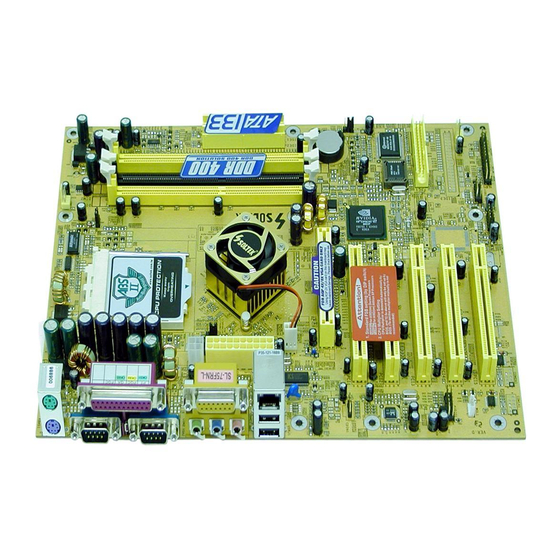
Page 6: 75Frn2 / 75Frn2-R / 75Frn2-L / 75Frn2-Rl Layout
Chapter 1 Specification 1-1 75FRN2 / 75FRN2-R / 75FRN2-L / 75FRN2-RL Layout RJ45 (75FRN2-L / RL Only) PS/2 Mouse Fan2 (on top) +12V Power PS/2 Keyboard (underside) USB0 USB0 (on top) (on top) USB1 (underside) ATX Main Power RJ45 (on top) USB2 (middle) USB3... -
Page 7: Mainboard Specifications
Series 75FRN2: 75FRN2, 75FRN2-L, 75FRN2-R, 75FRN2-RL 1-2 Mainboard Specifications 1-2.1 CPU Socket CPU Socket 462 (Socket A) on board, supporting AMD Athlon, Athlon XP and Duron processors and implementing 400/333/266/200MHz sys- tem bus 1-2.2 System Chipsets • North Bridge nVIDIA nFORCE2 Ultra 400 (nFORCE2 SPP) for managing and supporting 400/333/266/200MHz system Bus, AGP 8X/4X interface and DDR 333/266MHz Memory Interface with an enhanced support of DDR 400MHz Memory Module. -
Page 8: 1-2.5 Accelerated Graphics Port (Agp) Interface
Chapter 1 Specification 1-2.5 Accelerated Graphics Port (AGP) Interface AGP Controller embedded on board, supporting: • 1.5V(8X/4X) power mode only, 1 AGP Slot supported • 8X 66MHz AD and SBA signaling; AGP pipelined split-transaction long burst transfers up to 2GB/sec. •... -
Page 9: 1-2.9 Ac'97 Audio Codec On Board
• Hardware Monitor supported by LPC I/O W83627HF, providing moni- toring functions on hardware voltage, temperatures and fan speeds. • Utility Software Soltek Hardware Monitor for displaying monitor sta- tus is enclosed in Support CD for user’s installation. 1-2.11 Serial ATA RAID Controller (75FRN2-R / RL only) •... -
Page 10: Mainboard Specification Table
Chapter 1 Specification 1-3 Mainboard Specification Table Series 75FRN2 Specifications and Features Socket 462 for AMD Athlon, Athlon XP, Duron CPU nFORCE2 Ultra 400 (nFORCE2 SPP), supporting North Bridge 400/333/266/200 MHz FSB South Bridge nFORCE2 MCP Award BIOS BIOS Dual-channel DDR 400/333/266 SDRAM, up to Memory 3GB in 3 DDR DIMM slots I/O Chip... -
Page 11: Chipset System Block Diagram
Series 75FRN2: 75FRN2, 75FRN2-L, 75FRN2-R, 75FRN2-RL 1-4 Chipset System Block Diagram Socket 462 for AMD CPUs System Bus 400/333/266/200MHz Dual-channel North Bridge DDR memory nVIDIA Interface System nFORCE2 AGP 8X/4X AGP Slot Memory DDR 400/ Ultra 400 333/266 (nFORCE2 SDRAM SPP) HyperTransport 2 SATA ports+ 1 PATA port... - Page 12 Chapter 1 Specification Memo...
-
Page 13: Chapter 2 Hardware Setup
Series 75FRN2: 75FRN2, 75FRN2-L, 75FRN2-R, 75FRN2-RL Chapter 2 Hardware Setup To Get Things Ready for Hardware Setup ! 1. We recommend to install your CPU before any other components. For detailed installation instructions of processor, you can also refer to the pamphlet enclosed in your CPU package. 2. -
Page 14: Cpu Identification And Installation
Chapter 2 Hardware Setup 2-1 CPU Identification and Installation 2-1.1 CPU Identification Legends XXXXXXXXXXX XXXXXXXXXXXX XXXXXXX XXXXXXXXX XXXXXXXXXXX XXXX 0.13 um CPU 0.18um CPU AMD Athlon(Duron) AX 1900 D U T 3 C (1) (2) (3) (4) (5) (6) (7) Family / Architecture: A, AX, AXDA=AMD Athlon Processor D, DHD, DHM, DHL=AMD Duron Processor... -
Page 15: 2-1.2 Cpu Installation With Socket 462
Series 75FRN2: 75FRN2, 75FRN2-L, 75FRN2-R, 75FRN2-RL 2-1.2 CPU Installation with Socket 462 This mainboard is built with CPU Socket 462 supporting the AMD CPUs Athlon, Athlon XP and Duron: • Follow the steps described in this section to install CPU into the on- board Socket 462. -
Page 16: Memory Installation
Chapter 2 Hardware Setup 2-2 Memory Installation How to tackle the memory Modules: • Make sure to unplug your power supply before adding or removing memory module. Failure to do so may cause severe damage to both your mainboard and the memory module. •... -
Page 17: 2-2.2 Dual Channel Ddr Dimm Configuration
Series 75FRN2: 75FRN2, 75FRN2-L, 75FRN2-R, 75FRN2-RL 2-2.2 Dual Channel DDR DIMM configuration 1. To enable Dual Channel function on this series of mainboard, a DDR SDRAM module must be first inserted into DIM3, the Master Dual Chan- nel slot. 2. Next, either DIM1 or DIM2 or both should be inserted with DDR SDRAM module(s) to activate the Dual Channel function. -
Page 18: Agp Slot Installation
Chapter 2 Hardware Setup 2-3 AGP Slot Installation The AGP slot on board supports 1.5V AGP 8X/4X card only. A Rib is specifically added to the 8X/4X slot so as to match the AGP 8X/4X card. To insert a 3.3V AGP 2X card into the AGP 4X slot will damage the system chip and burn the 1.5V circuitry. - Page 19 Series 75FRN2: 75FRN2, 75FRN2-L, 75FRN2-R, 75FRN2-RL 2-4 IDE Connector Installation 1. To install IDE Connector, you may connect the blue connector of IDE cable to the primary (IDE1) or secondary (IDE2) connector on board, and then connect the gray connector to your slave device and the black connector to your master device.
-
Page 20: Floppy Drive Connector Installation
Chapter 2 Hardware Setup 2-5 Floppy Drive Connector Installation To install FDC, you should connect the end of FDC cable with single connector to the board, and connect the other end with two connectors to the floppy drives. PS/2 Mouse Fan2 (on top) +12V Power... -
Page 21: Serial Ata Connectors (75Frn2-R / Rl Only)
Series 75FRN2: 75FRN2, 75FRN2-L, 75FRN2-R, 75FRN2-RL 2-6 Serial ATA Connectors (75FRN2-R / RL Only) 2 Serial ATA connectors are built on board, supported by the SATA RAID Controller PDC20376. Before we install SATA RAID disk drive to the Serial ATA Connector, we must first enable the controller PDC20376 by Jumper Jp4 1-2 closed and then install the RAID Controller Driver (see Chapter 5 Disk Array Installation). -
Page 22: Atx Power Supply Installation
Chapter 2 Hardware Setup 2-7 ATX Power Supply Installation PS/2 +12V Power Connector Mouse Fan2 (on top) +12V Power PS/2 Keyboard +12V USB0 USB0 (underside) (on top) (on top) USB1 (underside) +12V ATX Main Power RJ45 (on top) USB2 (middle) USB3 (underside) +12V... -
Page 23: Jumper Settings
Series 75FRN2: 75FRN2, 75FRN2-L, 75FRN2-R, 75FRN2-RL 2-8 Jumper Settings The following diagrams show the locations and settings of jumper blocks on the mainboard. Jp5: Anti-burn Shield (ABSII) Jp2 : CPU Clock Select (Overheated CPU Shutdown) (only for Athlon XP/ (default) Duron Morgan) 1-2 closed For 100MHz / 133MHz... -
Page 24: 2-8.1 How To Tackle The Jumpers
Chapter 2 Hardware Setup 2-8.1 How to tackle the Jumpers: A 2-pin Jumper A 3-pin Jumper If a pin-header (of 2 or more pins) is designed in such a way that its pins can be closed or linked together to The conductor inside the cap set up a specific function, this header links two header-pins together. -
Page 25: 2-8.3 Jbat1: Nvidia Clear Cmos
Series 75FRN2: 75FRN2, 75FRN2-L, 75FRN2-R, 75FRN2-RL nVIDIA Boot-Failure-Reboot Procedures: Whenever nVIDIA system fails to boot (including overclock and non- overclock cases), it requires a more guaranteed Reboot Procedure to restart system. (1) To reboot nVIDIA system, users should first power off the system. (2) If a “CPU Clock Select”... -
Page 26: 2-8.4 Jp5: Anti-Burn Shield (Absii)
Chapter 2 Hardware Setup 2-8.4 Jp5: Anti-burn Shield (ABSII) Jp5: Anti-burn Shield (ABSII) (Overheated CPU Shutdown) (only for Athlon XP/ Duron Morgan) 1-2 closed (default) To enable overheated CPU C) shutdown function 2-3 closed To disable overheated CPU shutdown function Jp5 is designed to enable the overheat safeguard for some CPUs which are incorporated with a protective thermal diode. -
Page 27: 2-8.5 Jp1&Jp7: Ps/2 Kb/Mouse Power On
Series 75FRN2: 75FRN2, 75FRN2-L, 75FRN2-R, 75FRN2-RL 2-8.5 Jp1&Jp7: PS/2 KB/Mouse Power On Jp1 and Jp7 is designed to enable / disable PS/2 Keyboard/Mouse Power on function. Setting Jp1 and Jp7 to 1-2 closed will disable this function. Setting Jp1 and Jp7 to 2-3 closed will enable this function. Yet user still has to enter BIOS Setup for choosing the KB/ Mouse Power-on mode. -
Page 28: Other Connectors Configuration
Chapter 2 Hardware Setup 2-9 Other Connectors Configuration This section lists out all connectors configurations for users’ reference. 2-9.1 Onboard FAN Connectors Void PS/2 Sensor Mouse Fan2 (on top) +12V +12V Power PS/2 Keyboard USB0 (underside) USB0 (on top) (on top) USB1 +12V (underside) -
Page 29: 2-9.2 Usb Ports And Usb Pin-Headers
Series 75FRN2: 75FRN2, 75FRN2-L, 75FRN2-R, 75FRN2-RL 2-9.2 USB Ports and USB Pin-headers This series provides four USB ports on board supporting various USB devices. In addition, one USB pin-header is added on board to provide expansion of two more optional USB ports by using one additional USB Cable. -
Page 30: 2-9.3 Chassis Panel Connectors
Chapter 2 Hardware Setup 2-9.3 Chassis Panel Connectors A : PS/2 Mouse H : COM1 Connector B : USB 0 (top) : COM2 Connector C : LPT1 Port : USB 2 (middle) D : RJ45 (75FRN2-L/RL only) USB 3 (underside) E : Line in/ K : Microphone Input / Rear Speaker Out... -
Page 31: 2-9.5 Cd-Rom Audio Connectors
Series 75FRN2: 75FRN2, 75FRN2-L, 75FRN2-R, 75FRN2-RL 2-9.5 CD-ROM Audio Connectors CDIN1 is an audio connector connecting CD-ROM audio to mainboard. PS/2 Mouse Fan2 (on top) +12V Power PS/2 Keyboard CD-ROM Audio Connector USB0 (underside) USB0 (on top) (on top) USB1 (underside) CDIN1 Pin Signal... -
Page 32: 2-9.7 Wake On Lan Connector
Chapter 2 Hardware Setup 2-9.7 Wake On LAN Connector: 1. This connector connects to a PCI LAN card with a Ring signal output. The connector powers up the system when it receives a wake-up packet or signal through the LAN card. 2. -
Page 33: 2-9.8 Complex Pin-Header (Front Panel Connectors)
Series 75FRN2: 75FRN2, 75FRN2-L, 75FRN2-R, 75FRN2-RL 2-9.8 Complex Pin-header (Front Panel Connectors) This complex Pin-header consists of the following connectors for vari- ous front panel supports. When you have fixed the mainboard to the case, join the connectors of this Complex Pin-header to the case Front Panel. - Page 34 Chapter 2 Hardware Setup (1) SMI Connector (Optional): Connection: Connected to the Suspend Switch. Function: Manually selecting DOS system into the Suspend Mode or “Green Mode” by System Mangement Interupt. (2) Power Switch Connector: Connection: Connected to a momentary button or switch. Function: Manually switching the system between “On”...
-
Page 35: 2-9.9 Front Panel Audio Connector
Series 75FRN2: 75FRN2, 75FRN2-L, 75FRN2-R, 75FRN2-RL 2-9.9 Front Panel Audio Connector PS/2 Mouse Fan2 (on top) +12V Power PS/2 Keyboard USB0 USB0 (underside) (on top) (on top) This Mainboard is designed with a Front USB1 (underside) Panel Audio connector “JAUD1” which pro- vides connection to your chassis. -
Page 36: 2-9.12 6 Channel Sound Output Connector(Optional)
Chapter 2 Hardware Setup 2-9.12 6 Channel Sound Output Connector(Optional) This series is designed with a 6-channel Audio-out connector “Audio1”. If this option is chosen, it will provide 3 additional audio-out ports for the 6-channel sound. PS/2 Mouse Fan2 (on top) +12V Power PS/2 Keyboard USB0... -
Page 37: Chapter 4 Bios Setup
Chapter 4 BIOS Setup Chapter 4 BIOS Setup THE BIOS BIOS stands for Basic Input and Output System. It was once called ROM BIOS when it was stored in a Read-Only Memory(ROM) chip Now manufacturers would like to store BIOS in EEPROM which means Electrically Erasable Programmable Memory. -
Page 38: About Bios Setup
Series 75FRN2: 75FRN2, 75FRN2-L, 75FRN2-R, 75FRN2-RL 4-1 About BIOS Setup BIOS setup is an interactive BIOS program that you need to run when: 1. Changing the hardware of your system. (For example: installing a new Hard Disk etc.) 2. Modifying the behavior of your computer. (For example: changing the system time or date, or turning special features on or off etc.) 3. -
Page 39: To Upgrade Bios
Chapter 4 BIOS Setup 4-5 To Upgrade BIOS • System BIOS is incorporated into a Flash memory component. Flash BIOS allows user to upgrade BIOS without the need to replace an EPROM component. • The Upgrade Utility can be loaded on a floppy diskette to execute saving, verifying, and updating the system BIOS. - Page 40 Series 75FRN2: 75FRN2, 75FRN2-L, 75FRN2-R, 75FRN2-RL Step 4. Type awdflash *.bin /sn/py/cc and then press <Enter> to run BIOS upgrade program. (*.bin depends on your mainboard model and version code. Instead of typing “*”, you should type specific file name for your specific mainboard).
- Page 41 Chapter 4 BIOS Setup BIOS Update Illustration: (1) Executing the “awdflash.exe k8AV2008.bin” in DOS system, Award Flash Memory Writer Start Screen appears: To input BIOS file name. AwardBIOS Flash Utility V8.24F (C)Phoenix Technologies Ltd. All Rights Reserved For K8T800-8237-6A7L0SAAC-00 Date: 09/18/2003 File Name to Program : K8AV2008.BIN Message: Input the (BIOS) file name (2) Press Y if you want to back up your old BIOS.
- Page 42 Series 75FRN2: 75FRN2, 75FRN2-L, 75FRN2-R, 75FRN2-RL (4) Updating is in progress. Do not turn off power at this moment. AwardBIOS Flash Utility V8.24F (C)Phoenix Technologies Ltd. All Rights Reserved For K8T800-8237-6A7L0SAAC-00 Date: 09/18/2003 Flash Type - SST 39SF020 /5V File Name to Program : k8av2008.bin Writing Flash Memory - 0FE00 OK Write OK No Update...
-
Page 43: Bios Setup
Chapter 4 BIOS Setup 4-6 BIOS SETUP --- CMOS Setup Utility Warning and Tips: If changing CMOS Configuration causes difficulty in rebooting system, you can take the following measures: 1. At pressing the power button to reboot, press the “Insert” key at the same time. - Page 44 Series 75FRN2: 75FRN2, 75FRN2-L, 75FRN2-R, 75FRN2-RL 3. When one main item of the Main Menu is chosen and clicked on, its submenu will appear to display the related items and options. On the other hand, a list of operation guide will appear at the end of the submenu as below: :Move Enter: Select +/-/PU/PD: Value F10: Save ESC: Exit F1: General Help F5: Previous Values F6: Fail-Safe Defaults F7: Optimized Defaults...
-
Page 45: 4-6.2 Standard Cmos Setup
Chapter 4 BIOS Setup 4-6.2 Standard CMOS Setup Standard CMOS Setup records some basic system hardware configuration and sets the system clock and error handling. You only need to modify the configuration values of this option if you want to change your system hardware configuration or when the data stored in the CMOS memory gets lost or damaged. - Page 46 Series 75FRN2: 75FRN2, 75FRN2-L, 75FRN2-R, 75FRN2-RL Date (mm:dd:yy) The BIOS determines the day of the week from the other date information. This field is for information only. Press the left or right arrow key to move to the desired field (date, month, year). Press the PgUp or PgDn key to increment the setting, or type the desired value into the field.
- Page 47 Chapter 4 BIOS Setup Drive A / Drive B Select this field to the type(s) of floppy disk drive(s) installed in your system. The choices are: 360KB, 5.25 in. 1.2MB, 5.25 in. 720KB, 3.5 in. 1.44MB, 3.5 in. 2.88MB, 3.5 in. None Video Select the type of primary video subsystem in your computer.
-
Page 48: 4-6.3 Advanced Bios Features
Series 75FRN2: 75FRN2, 75FRN2-L, 75FRN2-R, 75FRN2-RL 4-6.3 Advanced BIOS Features Advanced BIOS Features improves your system performance or sets up system features according to your preference. Run the Advanced BIOS Features as follows: Choose “Advanced BIOS Features” from the Main Menu and a screen with a list of options will appear: Phoenix - AwardBIOS CMOS Setup Utility Advanced BIOS Features... - Page 49 Chapter 4 BIOS Setup Virus Warning When enabled, you receive a warning message if a program (specifically, a virus) attempts to write to the boot sector or the partition table of the hard disk drive. You should then run an antivirus program. Keep in mind that this feature protects only the boot sector, not the entire hard drive.
- Page 50 Series 75FRN2: 75FRN2, 75FRN2-L, 75FRN2-R, 75FRN2-RL Boot Up NumLock Toggle between On or Off to control the state of Status the NumLock key when the system boots. If On, the numeric keypad is in numeric mode. If off, the numeric keypad is in cursor control mode. Gate A20 Option Gate A20 refers to the way the system addresses memory above 1MB (extended memory).
-
Page 51: 4-6.4 Advanced Chipset Features
Chapter 4 BIOS Setup 4-6.4 Advanced Chipset Features Advanced Chipset Features is used to modify the values of chipset buffers. These buffers control the system options. Run the Advanced Chipset Features as follows: Choose “Advanced Chipset Features” from the Main Menu and a list of option will appear: Phoenix - AwardBIOS CMOS Setup Utility Advanced Chipset Features... - Page 52 Series 75FRN2: 75FRN2, 75FRN2-L, 75FRN2-R, 75FRN2-RL System Performance Allows you to set different system performance modes. Choices: Optimal; Aggressive; Turbo; Expert FSB Frequency To select an FSB for the CPU on board in accor- dance with the System Performance setting. Choices: 100MHz;...
- Page 53 Chapter 4 BIOS Setup AGP Aperture Size Series of options are available: 32, 64, 128, 256 or 512 MB. Memory mapped and graphics data struc- tures can reside in a Graphics Aperture. This area is like a linear buffer. BIOS will automatically report the starting address of this buffer to the O.S.
-
Page 54: 4-6.5 Integrated Peripherals
Series 75FRN2: 75FRN2, 75FRN2-L, 75FRN2-R, 75FRN2-RL 4-6.5 Integrated Peripherals Integrated Peripherals option allows you to get some information inside your system when it is working. Run the Integrated Peripherals as follows: Choose “Integrated peripherals” from the Main Menu and a list of options will appear: Phoenix - AwardBIOS CMOS Setup Utility Integrated Peripherals... - Page 55 Chapter 4 BIOS Setup On-Chip IDE Channel The chipset contains a PCI IDE interface with support from two IDE channels. Select Enabled to activate the first and/or the second IDE interface. Select Disabled to inactivate an inter- face if you install a primary and/or second add- on IDE interface.
- Page 56 Series 75FRN2: 75FRN2, 75FRN2-L, 75FRN2-R, 75FRN2-RL AC97 Audio Select “Enabled” to use the on-chip audio capability of your system. Most of the field do not appear when this field is “Disabled”, for user who wants to use add-on sound card, this item must be disabled. MAC LAN(nVIDIA) This option allows you to enable/disable the Onboard LAN Controller.
- Page 57 Chapter 4 BIOS Setup Onboard Serial Select a logical COM port name and matching Port 1 / Port 2 address for the first and second serial ports. Select an address and corresponding interrupt for the first and second serial ports. Choices: Disabled;...
- Page 58 Series 75FRN2: 75FRN2, 75FRN2-L, 75FRN2-R, 75FRN2-RL Use IR Pins When UART Mode is selected in IrDA or ASKIR mode, this item allows you to select the IR Pins signal selection. The choices: IR-Rx2Tx2; RxD2, TxD2 Onboard Parallel Port This item allows you to determine onboard parallel port controller I/O address setting.
-
Page 59: 4-6.6 Power Management Setup
Chapter 4 BIOS Setup 4-6.6 Power Management Setup Power Management Setup allows you to set the system’s power saving functions. Run the Power Management Setup as follows: Choose “Power Management Setup” from the Main Menu and a list of options will appear: Phoenix - AwardBIOS CMOS Setup Utility Power Management Setup Item Help... - Page 60 Series 75FRN2: 75FRN2, 75FRN2-L, 75FRN2-R, 75FRN2-RL ACPI Function Select Enabled(default) only if your computer’s op- erating system supports the Advanced Configura- tion and Power Interface (ACPI) specification. Currently, Windows NT 5.0 ( Windows 2000 )sup- ports ACPI. ACPI Suspend Type This item allows you to select the ACPI Suspend type.
- Page 61 Chapter 4 BIOS Setup HDD Down In Suspend Allows you to enable / disable(default) to power down HDD when suspend. Soft-Off by PBTN When Enabled, turning the system off by pressing the on/off button places the system in a very low- power-usage state.
-
Page 62: 4-6.7 Pnp / Pci Configuration
Series 75FRN2: 75FRN2, 75FRN2-L, 75FRN2-R, 75FRN2-RL 4-6.7 PnP / PCI Configuration PnP/PCI Configuration allows you to modify the system’s power saving functions. Run the PnP/PCI Configuration as follows: Choose “PnP/PCI Configuration” from the Main Menu and a screen with a list of options will appear: Phoenix - AwardBIOS CMOS Setup Utility PnP PCI Configurations Item Help... - Page 63 Chapter 4 BIOS Setup Reset Configuration Normally, you leave this Disabled(default). Select Data Enabled to reset Extended System Configuration Data (ESCD), when you exit Setup if you have in- stalled a new add-on and the system reconfiguration has caused such a serious conflict that the operat- ing system cannot boot.
-
Page 64: 4-6.8 Smartdoc Anti-Burn Shield
Series 75FRN2: 75FRN2, 75FRN2-L, 75FRN2-R, 75FRN2-RL 4-6.8 SmartDoc Anti-Burn Shield This section helps you to get more information about your system in- cluding CPU temperature, FAN speed and voltage. It is recommended that you contact your mainboard supplier to get proper values about the setting of the CPU temperature. - Page 65 Chapter 4 BIOS Setup ABS II Temp. (for AMD This item will appear if AMD XP or Duron Morgan XP/Duron Morgan) CPU is running on board. This item is to show the current temperature inside the running CPU. System Temp. Shows current system temperature. CPU External Temp.
-
Page 66: 4-6.9 Cpu Ratio/Voltage Control
Series 75FRN2: 75FRN2, 75FRN2-L, 75FRN2-R, 75FRN2-RL 4-6.9 CPU Ratio/Voltage Control Run the “CPU Ratio/Voltage Control” as following: Choose “CPU Ratio/Voltage Control” from the Main Menu and a screen with a list of options will appear: Phoenix - AwardBIOS CMOS Setup Utility CPU Ratio/Voltage Control Item Help CPU Ratio... -
Page 67: 4-6.10 Load Optimized Defaults
Chapter 4 BIOS Setup 4-6.10 Load Optimized Defaults When you press <Enter> on this item, you will get a confirmation dialog box with a message similar to: “ Load Optimized Defaults (Y / N) ? N ” Phoenix - AwardBIOS CMOS Setup Utility CPU Ratio/Voltage Control Standard CMOS Features Load Optimized Defaults... -
Page 68: 4-6.11 Set Supervisor / User Password
Series 75FRN2: 75FRN2, 75FRN2-L, 75FRN2-R, 75FRN2-RL 4-6.11 Set Supervisor / User Password These two options allow you to set your system passwords. Normally, the supervisor has a higher priority to change the CMOS setup option than the users. The way to set up the passwords for both Supervisor and Users are as follows: 1. -
Page 69: 4-6.12 Save & Exit Setup
Chapter 4 BIOS Setup 4-6.12 Save & Exit Setup SAVE & EXIT SETUP allows you to save all modifications you have specified into the CMOS memory. Please do not reset or power off until you see the boot screen. Highlight this option on the Main Menu and the following message appears: “Not To Reset Or Power-off Before Boot Screen Showed. -
Page 70: Chapter 5 Raid Controller
: 75FRN2, 75FRN2-L, 75FRN2-R, 75FRN2-RL Series 75FRN2 Chapter 5 RAID Controller (This Chapter is ONLY for 75FRN2-R and 75FRN2-RL) The following topics are included in this chapter: 5-0 Before Creating Disk Array 5-1 Creating your Disk Array 5-2 Installing RAID Controller PDC20376 Driver... -
Page 71: Before Creating Disk Array
Chapter 5 RAID Controller 5-0 Before Creating Disk Array: 1. Jp4 is a 3-pin jumper for enabling or disabling the on-board Serial ATA RAID Controller PDC20376. Setting Jp4 1-2 CLOSED will allow user to enable on-board RAID Controller so as to allow user to set up the Disk Array. -
Page 72: Creating Your Disk Array
: 75FRN2, 75FRN2-L, 75FRN2-R, 75FRN2-RL Series 75FRN2 5-1 Creating Your Disk Array To create your disk array, you have to open the FastBuild Utility, which should have already been built in the Promise Controller. At booting your system, you will see the following intiating screen: FastTrak 376(tm) BIOS Version xxxxxx (c) 2--2-2005 Promise Technology, Inc. - Page 73 Chapter 5 RAID Controller 2. Press <Ctrl-F> keys to display the FastBuild (tm) Utility Main Menu. Auto Setup ..........[ 1 ] View Drive Assignment ......[ 2 ] Define Array .........[ 3 ] Delete Array .........[ 4 ] Rebuild Array ........[ 5 ] 3.
-
Page 74: 5-1.2 Creating Security Array With Existing Data Drive
: 75FRN2, 75FRN2-L, 75FRN2-R, 75FRN2-RL Series 75FRN2 5-1.2 Creating Security Array With Existing Data Drive FastTrak 376 on board permits only two drives to be used for a single Mirroring (Security) array with FastBuild Utility. Checkpoints before creating a Security Array: (1) You may use a drive that is containing data or a bootable O/S. - Page 75 Chapter 5 RAID Controller 3. Press “1” to display the Auto Setup Menu below. This is the fastest and easiest method to create your first array. [Auto Setup Options Menu] Optimize Array for: Performance [Array Setup Configuration] Mode ..........Stripe Spare Drive ..........0 Drives used in Array ........1 Array Disk Capacity ......38166...
-
Page 76: Installing Drivers
: 75FRN2, 75FRN2-L, 75FRN2-R, 75FRN2-RL Series 75FRN2 5-2 Installing Drivers This section details the PDC 20376 FastTrak 376 driver installation for various operating systems. The driver should have been included ei- ther into the Support CD or into a Support Floppy Diskette. Checkpoints for the driver installation: 1. - Page 77 Chapter 5 RAID Controller Note: If you need to specify any additional devices to be installed, do so at this time. Once all devices are specified, continue to step 7. 7. From the Windows 2000/XP Setup screen, press the Enter key. Setup will now load all device files and then continue the Windows 2000/XP installation.
-
Page 78: 5-2.2 Windows 95/98
: 75FRN2, 75FRN2-L, 75FRN2-R, 75FRN2-RL Series 75FRN2 5-2.1-3 Confirming Windows 2000 Installation 1. From Windows 2000, open the Control Panel from “ My Computer” followed by the System icon. 2. Choose the “Hardware” tab, then click the “Device Manager” tab. 3. - Page 79 Chapter 5 RAID Controller 11. Insert the “FastTrak 376 Driver” diskette into the A: drive. 12. Press the “Next” button. A message informing you that Windows 98 has found “Win95-98 Promise FastTrak 376 (tm) Controller” should appear. 13. Press “Next,” then “Finish,” then “Yes” when asked if you want to restart your computer.
- Page 80 : 75FRN2, 75FRN2-L, 75FRN2-R, 75FRN2-RL Series 75FRN2 5-2.2-4 Installing Drivers With Existing Windows 95/98 The following three sections detail the installation of the FastTrak 376 driv- ers on a system that has Windows 95/98 already installed. If you’re installing the FastTrak 376 drivers on a system during a Windows 95/98 installation, see “Installing Drivers During Windows 95/98 Installation”.
-
Page 81: 5-2.3 Dos/Windows 3.1X
Chapter 5 RAID Controller 7. Choose “Yes” when asked whether you want to start your computer. Be sure to remove the diskette from drive A. 5-2.2-7 Confirming Driver Installation in Windows 98/95 To confirm that the driver has been properly loaded in Win 95/98, perform the following steps: 1. -
Page 82: 5-2.4 Windows Nt4.0
: 75FRN2, 75FRN2-L, 75FRN2-R, 75FRN2-RL Series 75FRN2 5-2.4 Windows NT4.0 5-2.4-1 Installing Drivers During Windows NT 4.0 Installation 1. Connect your hard drive(s) for RAID Array to IDE3/ATA1/ATA2, and enable FastTrak 376 Controller by Jp4. Start the system installation by booting from the Windows NT disk: a) Floppy install: boot the system with the Windows NT installation diskettes. - Page 83 Chapter 5 RAID Controller 5-2.4-2 Installing Drivers With Existing Windows NT4.0 W A R N I N G : W A R N I N G : Your must first complete installing the driver before moving the boot drive containing the existing Windows 2000 operating system on to the FastTrak 376 controller (e.g.
Need help?
Do you have a question about the 75FRN2 Series and is the answer not in the manual?
Questions and answers