Table of Contents
Advertisement
KT400-C
Chapter 1 Specification ............................................. 8
1-1 KT400-C Mainboard Layout** ..............................................9
1-2 Mainboard Specifications .................................................... 10
1-2.1 CPU Socket ................................................................................... 10
1-2.2 System Chipsets ........................................................................... 10
1-2.3 Memory ......................................................................................... 10
1-2.4 BIOS ............................................................................................... 10
1-2.5 Accelerated Graphics Port (AGP) Interface ........................... 10
1-2.6 Advanced System Power Management .................................... 11
1-2.7 Multi-I/O Functions .................................................................... 11
1-2.8 Expansion Slots ............................................................................ 11
1-2.9 AC'97 Audio Codec on board .................................................... 12
1-2.10 Hardware Monitor on board ................................................... 12
1-2.11 Form Factor ................................................................................ 12
1-3 Mainboard Specification Table ........................................... 13
1-4 Chipset System Block Diagram ........................................... 14
Chapter 2 Hardware Setup ..................................... 16
2-1 CPU Identification and Installation ................................... 17
2-1.1 CPU Identification Legends ....................................................... 17
2-1.2 CPU Installation with Socket 462 ............................................. 18
2-2 Memory Installation ............................................................. 19
2-2.1 To Install DDR SDRAM Module .............................................. 19
2-2.2 To Remove a DIMM .................................................................... 20
2-3 AGP Slot Installation ............................................................ 21
2-4 IDE Connector Installation ................................................. 22
2-5 Floppy Drive Connector ( FDC ) Installation ................... 23
2-6 ATX Power Supply Installation .......................................... 24
Contents
4
Advertisement
Table of Contents

Related Manuals for SOLTEK KT400-C


Summary of Contents for SOLTEK KT400-C
-
Page 1: Table Of Contents
KT400-C Contents Chapter 1 Specification ..........8 1-1 KT400-C Mainboard Layout** ..........9 1-2 Mainboard Specifications ............ 10 1-2.1 CPU Socket ................... 10 1-2.2 System Chipsets ................10 1-2.3 Memory ..................10 1-2.4 BIOS ....................10 1-2.5 Accelerated Graphics Port (AGP) Interface ......10 1-2.6 Advanced System Power Management ........ - Page 2 Contents 2-7 Jumper / Switch Settings ............25 2-7.1 How to tackle the Jumpers: ............26 2-7.2 SW1: CPU Clock/Overclock Select .......... 26 2-7.3 JBAT1: Clear CMOS ..............27 2-7.4 Jp1: Anti-burn Shield (ABSII) ..........28 2-7.5 JP2: KB/Mouse Power On / Wake Up ........29 2-8 Other Connectors Configuration ........
- Page 3 KT400-C 4-5 To Update BIOS ..............50 4-6 BIOS SETUP --- CMOS Setup Utility ........ 52 4-6.1 CMOS Setup Utility ..............52 4-6.2 Standard CMOS Setup ............... 53 4-6.3 Advanced BIOS Features ............56 4-6.4 Advanced Chipset Features ............59 4-6.5 Power Management Features ............
- Page 4 Contents ITEM CHECKUP • Mainboard • Mainboard User Manual • Multi-lingual Quick Installation Guide • Support CD • Bundled Bonus Pack CD • Bundled Bonus Pack Manual • Cables : ATA66/100/133 IDE Cable FDD Cable USB Cable (Optional)
-
Page 5: Chapter 1 Specification
KT400-C Chapter 1 Specification Introduction This mainboard features an integration of the powerful AMD proces- sors Athlon/Athlon XP/Duron and the North Bridge VIA Apollo KT400 plus South Bridge VT8235, with which the whole system performance supports 333/266/200 MHz system bus. -
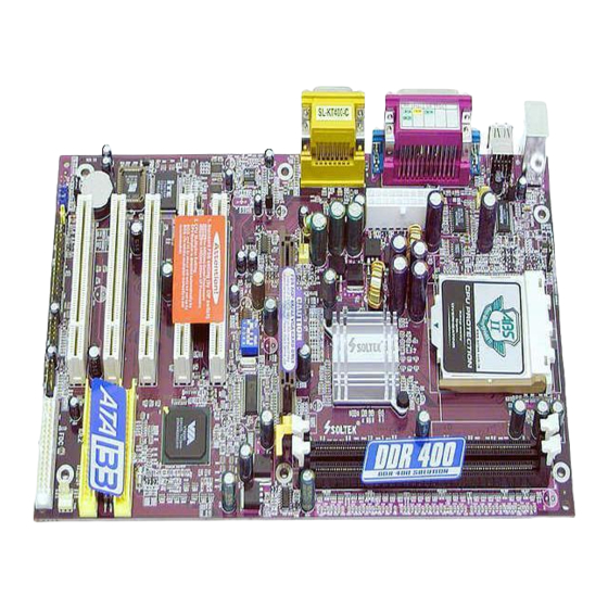
Page 6: Kt400-C Mainboard Layout
Chapter 1 Specification 1-1 KT400-C Mainboard Layout** Mouse (on top) PS/2 K/B (underside) USB0 (on top) USB1 (underside) KT400 Fan2 AGP 8X/4X CD-In1 Clock Generator ALC202A PCI 1 AC'97 Codec PCI 2 VT8235 LPC I/O PCI 3 IT8705 IDE1 PCI 4... -
Page 7: Mainboard Specifications
200MHz system Bus, AGP 8X/4X interface and DDR 333/266MHz Memory Interface *with an enhanced support of DDR 400MHz Memory Module which should have passed Soltek DDR 400 Memory Module Validation. • South Bridge VIA VT8235 working with North Bridge KT400 supporting the V-Link, LPC Super I/O, PCI interface, ATA133 interface, USB V2. -
Page 8: 1-2.6 Advanced System Power Management
Chapter 1 Specification 1-2.6 Advanced System Power Management Advanced Configuration and Power Interface incorporated in BIOS for reducing power consumption : • ACPI 1.0 compliant (Advanced Configuration and Power Interface) • APM V1.2 compliant (Legacy Power Management) • ACPI Suspend function supported •... -
Page 9: 1-2.9 Ac'97 Audio Codec On Board
KT400-C 1-2.9 AC’97 Audio Codec on board AC’97 Audio Codec on board, 2-channel interface compliant 1-2.10 Hardware Monitor on board • Hardware Monitor integrated in LPC I/O IT8705F, providing monitor- ing functions on hardware voltage, temperatures and fan speeds. • Utility Software SmartGuardian for displaying monitor status is en- closed in Support CD for user’s installation. -
Page 10: Mainboard Specification Table
Chapter 1 Specification 1-3 Mainboard Specification Table KT400-C Specifications and Features Socket 462 for AMD Athlon, Athlon XP, Duron CPU North Bridge VIA KT400, supporting 333/266/200 MHz FSB South Bridge VT8235 BIOS AMI BIOS Memory Supporting DDR *400/333/266 SDRAM, up to 2GB... -
Page 11: Chipset System Block Diagram
KT400-C 1-4 Chipset System Block Diagram Socket 462 for AMD CPUs System Bus 333/266/200MHz DDR memory Interface System VIA KT400 AGP 8X/4X AGP Slot Memory North Bridge DDR 400/ 333/266 SDRAM V-Link 5 PCI Slots PCI Bus 4 IDE ATA 133/100/66... -
Page 12: Chapter 2 Hardware Setup
KT400-C Chapter 2 Hardware Setup To Get Things Ready for Hardware Setup ! 1. We recommend to install your CPU before any other components. For detailed installation instructions of processor, you can also refer to the pamphlet enclosed in your CPU package. -
Page 13: Cpu Identification And Installation
Chapter 2 Hardware Setup 2-1 CPU Identification and Installation 2-1.1 CPU Identification Legends XXXXXXXXXXX XXXXXXXXXXXX XXXXXXX XXXXXXXXX XXXXXXXXXXX XXXX .18 micron process CPU .13 micron process CPU AMD Athlon(Duron) AX 1900 D M T 3 C (1) (2) (3) (4) (5) (6) (7) Family / Architecture: A, AX, AXDA=AMD Athlon Processor D, DHD=AMD Duron Processor... -
Page 14: 2-1.2 Cpu Installation With Socket 462
KT400-C 2-1.2 CPU Installation with Socket 462 This mainboard is built with CPU Socket 462 supporting the AMD CPUs Athlon, Athlon XP and Duron: • Follow the steps described in this section to install CPU into the on- board Socket 462. -
Page 15: Memory Installation
BIOS Setup. DDR 400 Module is supported on condition that the module has passed Soltek DDR 400 Memory Module Validation Test. Soltek Computer Inc. typically runs a DDR 400 Memory Module Validation Program for Chipset VIA KT400/P4X400A. Detailed information is available in Soltek Web Site: www.soltek.com.tw... -
Page 16: 2-2.2 To Remove A Dimm
KT400-C 2-2.2 To Remove a DIMM Press down the holding latches on both sides of slot to release the module from the DIMM slot. D D R D I M M S l o t s (184-pin) Mouse (on top) -
Page 17: Agp Slot Installation
Chapter 2 Hardware Setup 2-3 AGP Slot Installation The AGP slot on board supports 1.5V AGP 8X/4X card only. A Rib is specifically added to the 8X/4X slot so as to match the AGP 8X/4X card. To insert a 3.3V AGP 2X card into the AGP 4X slot will damage the system chip and burn the 1.5V circuitry. -
Page 18: Ide Connector Installation
KT400-C 2-4 IDE Connector Installation To install IDE Connector, you may connect the blue connector of IDE cable to the primary (IDE1) or secondary (IDE2) connector on board, and then connect the gray connector to your slave device and the black connector to your master device. -
Page 19: Floppy Drive Connector ( Fdc ) Installation
Chapter 2 Hardware Setup 2-5 Floppy Drive Connector ( FDC ) Installation To install FDC, you should connect the end of FDC cable with single connector to the board, and connect the other end with two connectors to the floppy drives. Mouse (on top) (underside) -
Page 20: Atx Power Supply Installation
KT400-C 2-6 ATX Power Supply Installation Mouse (on top) (underside) PS/2 K/B USB0 (on top) USB1 (underside) +12V PWR OK KT400 PS ON# Fan2 AGP 8X/4X CD-In1 Clock +3.3V -12V Generator ALC202A PCI 1 AC'97 Codec +3.3V +3.3V PCI 2... -
Page 21: Jumper / Switch Settings
Chapter 2 Hardware Setup 2-7 Jumper / Switch Settings The following diagrams show the locations and settings of jumper / switch blocks on the mainboard. Anti-burn Shield (ABSII) JP1: (Overheated CPU Shutdown) (only for Athlon XP/Duron Morgan) 1-2 closed (default) Enable overheated CPU (85 C) shutdown function 2-3 closed... -
Page 22: 2-7.1 How To Tackle The Jumpers
KT400-C 2-7.1 How to tackle the Jumpers: A 2-pin Jumper A 3-pin Jumper If a pin-header (of 2 or more pins) is designed in such a way that its pins can be closed or linked together to The conductor inside the cap set up a specific function, this header links two header-pins together. -
Page 23: 2-7.3 Jbat1: Clear Cmos
Chapter 2 Hardware Setup Further notes on CPU Overclocking: 1. If you have successfully booted system with or without CPU overclock, you still can do another CPU overclock in BIOS Setup. Please enter BIOS Setup, choose “Frequency/Voltage Control” menu, and take the “Use Linear”... -
Page 24: 2-7.4 Jp1: Anti-Burn Shield (Absii)
KT400-C 2-7.4 Jp1: Anti-burn Shield (ABSII) JP1: Anti-burn Shield (ABSII) (Overheated CPU Shutdown) (only for Athlon XP/ Duron Morgan) 1-2 closed (default) Enable overheated CPU C) shutdown function 2-3 closed Disable overheated CPU shutdown function JP1 is designed to enable the overheat safeguard for some CPUs which are incorporated with a protective thermal diode. -
Page 25: 2-7.5 Jp2: Kb/Mouse Power On / Wake Up
Chapter 2 Hardware Setup 2-7.5 JP2: KB/Mouse Power On / Wake Up JP2 is designed on board as a jumper to enable/disable the PS/2 key- board/mouse Power On/Wake Up from system off or suspend mode. Yet users should still enter BIOS setup to choose the Wake Up/ Power On mode. -
Page 26: Other Connectors Configuration
KT400-C 2-8 Other Connectors Configuration This section lists out all connectors configurations for users’ reference. 2-8.1 On-board FAN Connectors Void +12V +12V SENSOR Sensor Conn. Mouse (on top) PS/2 K/B (underside) No Sensor USB0 (on top) USB1 (underside) FAN1, Sensor Fan Connector... -
Page 27: 2-8.2 Usb Ports And Usb Pin-Headers
Chapter 2 Hardware Setup 2-8.2 USB Ports and USB Pin-headers This series provides two USB ports USB0 and USB1 on board sup- porting various USB devices. In addition, two USB pin-headers are added on board to provide expansion of four more optional USB ports by using two additional USB Cables. -
Page 28: 2-8.3 Chassis Panel Connectors
KT400-C 2-8.3 Chassis Panel Connectors G : COM 1 A : PS/2 Mouse H : COM 2 B : Port USB 0 : Line Out C : LPT1 PORT J : Line In D : Game/MIDI K : Microphone Input... -
Page 29: 2-8.5 Cd-Rom Audio Connectors (Cd-In1)
Chapter 2 Hardware Setup 2-8.5 CD-ROM Audio Connectors (CD-In1) CD-In1 is an audio connector connecting CD-ROM audio to mainboard. Mouse (on top) PS/2 K/B (underside) USB0 (on top) CD-ROM Audio Connector USB1 (underside) CD-In1 Pin Signal KT400 Pin 1 Left Channel Fan2 AGP 8X/4X CD-In1... -
Page 30: 2-8.6 Thermal Connectors
KT400-C 2-8.6 Thermal Connectors Mouse (on top) PS/2 K/B (underside) USB0 (on top) RT1 is mounted USB1 (underside) with Thermal Resistor by default. KT400 Fan2 AGP 8X/4X To Devices CD-In1 Clock Generator ALC202A PCI 1 AC'97 To RT2 Codec PCI 2... -
Page 31: 2-8.7 Complex Pin-Header (Front Panel Connectors)
Chapter 2 Hardware Setup 2-8.7 Complex Pin-header (Front Panel Connectors) This complex Pin-header consists of the following connectors for vari- ous front panel supports. When you have fixed the mainboard to the case, join the connectors of this Complex Pin-header to the case Front Panel. - Page 32 KT400-C (1) SMI Connector (Optional): Connectedion: Connected to the Suspend Switch. Function: Manually selecting DOS system into the Suspend Mode or “Green Mode” by System Mangement Interupt. (2) Power Switch Connector: Connectedion: Connected to a momentary button or switch. Function: Manually switching the system between “On” and “Soft Off”.
-
Page 33: 2-8.8 Jaud1: Front Panel Audio Connector (Optional)
Chapter 2 Hardware Setup 2-8.8 JAUD1: Front Panel Audio Connector (optional) This Mainboard is designed with a Front Panel Audio connector “JAUD1” which provides connection to your chassis. 1. When JAUD1 is set to 5-6 closed and 9-10 closed, this default setting disables this connector and leaves the Back Panel Audio enabled. -
Page 34: Chapter 3 Software Setup
KT400-C Chapter 3 Software Setup Drivers, Utilities and Software Installation Support CD: This mainboard will be shipped with a Support CD which contains those necessary driver files, Application Softwares and some helpful utilities. It is a user-friendly, auto-run CD which will open itself up in a CD-ROM automatically. -
Page 35: Open Up Support Cd
Chapter 3 Software Setup 3-1 Open Up Support CD: 1. Please put the Support CD enclosed in your mainboard package into the CD-ROM drive. In a few seconds, the Main Menu will automatic ally appear, displaying the contents to be installed for this series: 2. -
Page 36: Proceed To Via 4-In-1 Drivers Installation
KT400-C 3-2 Proceed to VIA 4-IN-1 Drivers Installation 1. Following the procedures of opening the Support CD, click to “ VIA 4- in-1 Drivers” to proceed. 3. “VIA Service Pack README” 2 . T h e V I A S e r v i c e P a c k... - Page 37 Chapter 3 Software Setup 7. Click on “Click to enable DMA 6 . S e l e c t “ I n s t a l l V I A ATA P I Mode” checkbox to enable V e n d o r S u p p o r t D r i v e r ” DMA function, then click the checkbox, then click the “Next”...
-
Page 38: Proceed To Ac'97 Audio Driver Installation
KT400-C 3-3 Proceed to AC’97 Audio Driver Installation 1 Following the installation of VIA 4in1 drivers, you have to restart system so that your system can be reconfigured with VIA 4in1. When restarting procedures finish, please open the Support CD with your CD-ROM to enter the Main Installation Menu. -
Page 39: Install Usb 2.0 Driver For Win98 / Me / 2000 / Xp
Chapter 3 Software Setup 3-4 Install USB 2.0 Driver for Win98 / Me / 2000 / XP VIA USB V2.0 is already integrated on board. Its 480Mb/s transfer rate supports operating system Win98/Me/2000/XP. USB Driver installa- tion procedures are of similar steps in these systems. Please take the following illustrations from Win XP as the USB driver installation guide: 1. - Page 40 KT400-C 3. Instantly, next screen will pop up to prompt you to select component. Select “Install USB Driver” and click “Next” button to continue. Next 4. The USB 2.0 Setup Program will then guide you through the whole driver setup (including the acceptance of License Agreement)until the “Finish”...
-
Page 41: To Install Hardware Monitor Utility
Following the procedures of opening the Support CD, click to “ Hardware Monitor Utility” to proceed. Then the installation program automatically opens the “Soltek HM Setup” screen. Click “OK” to continue. `äáÅâ Select the Program folder and click “Install” to continue. -
Page 42: 3-5.2 Verification
KT400-C 3-5.2 Verification 1. After installing Soltek Hardware Monitor, double click “SoltekHM” icon on the desktop to open the main window of the Soltek Hardware Doctor. Then the pop-up screen will show all information about CPU Temperature, Fan Speed and various Voltages. -
Page 43: Chapter 4 Ami Bios Setup
KT400-C Chapter 4 AMI BIOS Setup THE BIOS BIOS stands for Basic Input and Output System. It was once called ROM BIOS when it was stored in a Read-Only Memory (ROM) chip Now manufacturers would like to store BIOS in EEPROM which means Electrically Erasable Programmable Memory. -
Page 44: About Bios Setup
Chapter 4 BIOS Setup 4-1 About BIOS Setup BIOS setup is an interactive BIOS program that you need to run when: 1. Changing the hardware of your system. (For example: installing a new Hard Disk etc.) 2. Modifying the behavior of your computer. (For example: changing the system time or date, or turning special features on or off etc.) 3. -
Page 45: To Update Bios
KT400-C 4-5 To Update BIOS • System BIOS is incorporated into a Flash memory component. Flash BIOS allows user to upgrade BIOS without the need to replace an EPROM component. • The Upgrade Utility can be loaded on a floppy diskette for upgrading saving, and verifying the system BIOS. - Page 46 Chapter 4 BIOS Setup Step 4. Type AMIFLASH *.ROM and then press <Enter> to run BIOS update program. (*.ROM will vary, depending on your mainboard model and version code. Instead of typing “*”, you should type specific file name for your specific mainboard. For example: AMIFLASH(space) 75FRV11.ROM).
-
Page 47: Bios Setup
KT400-C 4-6 BIOS SETUP --- CMOS Setup Utility 4-6.1 CMOS Setup Utility This mainboard comes with the AMI BIOS from American Megatrends Inc. Enter the CMOS Setup Utility Main Menu by: 1. Turn on or reboot your system. After a series of diagnostic checks, the following message will appear: PRESS <Del>... -
Page 48: 4-6.2 Standard Cmos Setup
Chapter 4 BIOS Setup 4-6.2 Standard CMOS Setup Standard CMOS Setup records some basic system hardware configuration and sets the system clock and error handling. Modify the configuration values of this option if you want to change your system hardware configuration or after you clear CMOS data. Run the Standard CMOS Setup as follows: 1. - Page 49 KT400-C System Time The BIOS shows the time of the day in the format: hh:mm:ss. Choose the field with the Arrow keys and change the time with the Page Up/Page Down +/- keys. System Date The BIOS shows the date of the day in the format: mm:dd:yy :day of the Week.
- Page 50 Chapter 4 BIOS Setup Type This option shows the types of configuration for the IDE devices: 1-50: Predefined types USER: set Parameters by User Auto: Set parameters automatically CD-ROM: Use for ATAPI CD-ROM drives Double click [Auto] to set all HDD parameters automatically, including “Cylinders, Heads, Write Precompensation, Sectors, Maximum Capacity and 32 Bit Transfer Mode.
-
Page 51: 4-6.3 Advanced Bios Features
KT400-C 4-6.3 Advanced BIOS Features Advanced BIOS Features improves your system performance or sets up system features according to your preference. Run the Advanced BIOS Features as follows: 1. Choose “Advanced BIOS Features” from the Main Menu and a screen with a list of options will appear: AMIBIOS NEW SETUP UTILITY - VERSION 3.31a... - Page 52 Choises: Yes; No Initial Display Mode If option is “Silent”, the initial display mode is set to one with Soltek logo. If option is “BIOS”, initial dis- play will hide logo. Choices: Silent (default); BIOS If the item “Initial Display Mode” is set to “Silent”, two Display Mode at Add- other sub-modes are provided for this item.
- Page 53 KT400-C Bootup Num-lock Allows you to toggle between On or Off to control the state of the NumLock keys when the system boots. If On, the numeric keypad is in numeric mode. If off, the numeric keypad is in cursor con- trol mode.
-
Page 54: 4-6.4 Advanced Chipset Features
Chapter 4 BIOS Setup 4-6.4 Advanced Chipset Features Advanced Chipset Features is used to modify the values of chipset buffers. These buffers control the system options. Run the Advanced Chipset Features as follows: 1. Choose “Advanced Chipset Features” from the Main Menu and a list of option will appear: AMIBIOS NEW SETUP UTILITY - VERSION 3.31a Advanced Chipset Features... - Page 55 KT400-C Configure SDRAM SPD (Serial presence detect) is a device in memory Timing by SPD module for storing the module information such as DRAM timing and chip parameters. If this option is enabled, BIOS will access SPD automatically to configure module timing. If disabled, DRAM timing can be configured manually.
- Page 56 Chapter 4 BIOS Setup AGP Aperture Size Allows you to set the AGP Aperture Size. Choices: 4MB; 8MB; 16MB; 32MB; 64MB; 128MB; 256MB; AGP Master 1 W/S Allows you to enable / disable (default) the support Write of AGP Master 1 Waite State Write. AGP Master 1 W/S Allows you to enable / disable (default) the support Read...
-
Page 57: 4-6.5 Power Management Features
KT400-C 4-6.5 Power Management Features Power Management Features allows you to set the system’s power saving functions. Run the Power Management Features as follows: 1. Choose “Power Management Features” from the Main Menu and a list of options will appear: AMIBIOS NEW SETUP UTILITY - VERSION 3.31a... - Page 58 Chapter 4 BIOS Setup ACPI Standby State This item allows you to select the ACPI Suspend type. You can select S3(STR) for suspending to DRAM if your system supports this mode. Or you can select S1 (POS) for Power on Suspend under Windows 98 or later O/S ACPI mode..
- Page 59 KT400-C Resume On RTC Alarm Allows you to enable / disable the Resume On RTC Alarm function. RTC Alarm Date / Hour If resume On RTC Alarm is enabled, this field al- / Minute lows you to set the Alarm date Hour, Minute and second.
-
Page 60: 4-6.6 Pnp / Pci Configurations
Chapter 4 BIOS Setup 4-6.6 PNP / PCI Configurations PNP/PCI Configuration allows you to modify the system’s power saving functions. Run the PNP/PCI Configurations as follows: 1. Choose “PNP/PCI Configurations” from the Main Menu and a screen with a list of options will appear: AMIBIOS NEW SETUP UTILITY - VERSION 3.31a PNP/PCI Configurations Setup Help... - Page 61 KT400-C Plug and Play Aware Allows BIOS to recognize the Plug and Play Aware Operating System. Choices: No (default); Yes Clear NVRAM Allows BIOS to clear the NVRAM data. Choices: No (default); Yes PCI Latency Timer (PCI Allows you to set the PCI Latency Time.
-
Page 62: 4-6.7 Integrated Peripherals
Chapter 4 BIOS Setup 4-6.7 Integrated Peripherals Integrated Peripherals option allows you to get some information inside your system when it is working. Run the Integrated Peripherals as follows: 1. Choose “Integrated Peripherals” from the Main Menu and a list of options will appear: AMIBIOS NEW SETUP UTILITY - VERSION 3.31a Integrated Peripherals... - Page 63 KT400-C Onboard FDC Allows you to enable / disable the Onboard FDC. Choices: Auto; Enabled; disabled Onboard Serial Port 1 Allows you to set the Onboard Serial Port A. Choices; auto; Disabled; 3F8/COM1; 2F8/COM2; 3E8/COM3; 2E8/COM4; Onboard Serial Port 2 Allows you to set the Onboard Serial Port B.
- Page 64 Chapter 4 BIOS Setup Onboard IDE Allows you to choose the Onboard IDE Mode. Choices: Disabled; Primary; Secondary; Both Onboard AC‘97 Audio Allows you to disable or set AC’97 Audio automati- cally by system. Choices: Auto; Disabled...
-
Page 65: 4-6.8 Smartdoc Anti-Burn Shield
KT400-C 4-6.8 SmartDoc Anti-Burn Shield This menu helps you to read only and get more information on the working CPU temperature, FAN speed and voltage. 1. Choose “SmartDoc Anti-Burn Shield” from the Main Menu and a screen with a list of current status of your working system will appear: AMIBIOS NEW SETUP UTILITY - VERSION 3.31a... - Page 66 Chapter 4 BIOS Setup CPU Shutdown Tem- This feature allows you to set the shutdown tem- perature perature to the running CPU. Choices: Disabled; 50 C~71 C in 3˚ C stepping CPU Fan Low Speed This feature allows you to set up the CPU Fan Low Warning Speed warning function.
-
Page 67: 4-6.9 Frequency/Voltage Control
KT400-C 4-6.9 Frequency/Voltage Control Run the “Frequency/Voltage Control” as following: 1. Choose “Frequency/Voltage Control” from the Main Menu and a screen with a list of options will appear: AMIBIOS NEW SETUP UTILITY - VERSION 3.31a Frequency/Voltage Control Setup Help RedStorm Overclocking Tech... - Page 68 Chapter 4 BIOS Setup (Optional) If this option is chosen in BIOS, press <Enter> to Redstorm Overclock- start RED STORM OVERCLOCKING TECH. This option helps user to raise CPU clock automatically Tech until an unacceptable valueis reached. Then BIOS will restart your systemwith a highest accept- able CPU clock.
-
Page 69: 4-6.10 System Information
KT400-C 4-6.10 System Information This menu helps you to read only and get more information on the system. 1. Choose “System Information” from the Main Menu and a screen with a list of current status of your working system will appear: AMIBIOS NEW SETUP UTILITY - VERSION 3.31a... -
Page 70: 4-6.11 Set Supervisor Password
Chapter 4 BIOS Setup 4-6.11 Set Supervisor Password This option allows you to set a Supervisor password for the system: 1. Choose “Set Supervisor Password” in the Main Menu and press <Enter>. Then the following message appears: [ Enter new supervisor password ] 2. - Page 71 KT400-C 8. To change or remove a current supervisor password, choose “Set Supervisor Password” and press <Enter>. An instruction box appears on the screen, prompting you to enter the current password first: [ Enter current supervisor password ] 9. Type the current password with keyboard and then press <Enter>.
-
Page 72: 4-6.12 Load Optimized Defaults
Chapter 4 BIOS Setup 4-6.12 Load Optimized Defaults When you press <Enter> on this item, you will get a confirmation dialog box with a message similar to: [ Load Optimized Settings ] Press [Enter] to continue or [ESC] to abort Press <Enter>...
Need help?
Do you have a question about the KT400-C and is the answer not in the manual?
Questions and answers