Table of Contents
Advertisement
Quick Links
Advertisement
Table of Contents

Related Manuals for SOLTEK SL-75KAV


Summary of Contents for SOLTEK SL-75KAV
- Page 1 SL-75KAV/75KAV-X USER MANUAL V1.0...
- Page 2 In no event shall Soltek computer inc. Be liable for any loss or profits, loss of business, loss of use or data, interruption of business, or for indirect, special, incidental, or con- sequential damages of any kind, even if Soltek computer inc.
- Page 3 SOLTEK AROUND THE WORLD SOLTEK COMPUTER INC. Address : 7F, No. 306-3, Ta-Tung Rd, Sec.1, Hsi-Chin, Taipei- Hsien, Taiwan, R.O.C. Telephone : 886-2-2642-9060 : 886-2-2642-9065 E-mail : sashia@soltek.com.tw Web site : http://www.soltek.com.tw SOLTEK KOREA INC. Address : 1002, Chungjin Bldg. 53-5 Wonhyo-Ro, 3-Ka,...
-
Page 4: Table Of Contents
75KAV/75KAV-X C O N T E N T Chapter 1 INTRODUCTION ............7 1-1 ITEM LIST CHECKUP ..............7 1-2 PROCESSOR ................7 1-3 CHIPSET ..................7 1-4 ADVANCED HIGH PERFORMANCE DRAM CONTROLLER ..7 1-5 FULL FEATURED ACCELERATED GRAPHICS PORTS (AGP) CONTROLLER ................ - Page 5 75KAV/75KAV-X 2-8 JUMPER DEFINITIONS ............. 23 2-8.1 ONBOARD FAN CONNECTOR (FAN1/FAN2) ......23 2-8.2 USB PORT SELECT (JP1/JP2) ..........25 2-8.3 FACTORY (JP3) ............... 25 2-8.4 POWER LOST RESUME (JP7) ..........25 2-8.5 USB WAKE UP (JP9) .............. 25 2-8.6 MEMORY MODULE VOLTAGE SELECT (JP10/JP11) .... 25 2-8.7 CLEAR CMOS DATA (JBAT1) ..........
- Page 6 75KAV/75KAV-X Chapter 4 BIOS Setup ..............45 4-1 INTRODUCE THE BIOS ............. 45 4-2 WHAT IS BIOS SETUP ............... 45 4-3 HOW TO RUN BIOS SETUP ............45 4-4 WHAT IS CMOS ................. 45 4-5 WHAT IS POST ................46 4-6 BIOS UPGRADE .................
-
Page 7: Chapter 1 Introduction
75KAV/75KAV-X CHAPTER 1 INTRODUCTION 1-1 ITEM LIST CHECKUP • Motherboard • Support CD • User’s Manual • Bundle Bonus Pack CD • Bundle Bonus Pack Manual • Temperature Sensor Cable • ATA 66/100 IDE Cable • Temperature Sensor Cable • RS232 Cable •... -
Page 8: Full Featured Accelerated Graphics Ports (Agp) Controller
75KAV/75KAV-X 1-5 FULL FEATURED ACCELERATED GRAPHICS PORTS (AGP) CONTROLLER • Synchronous and pseudo-synchronous with the host CPU bus with optimal skew control PCI AGP Mode 33MHz/66MHz/100MHz DDR 3x synchro- nous • Supports 66MHz 1x, 2x and 4x modes for AD and SBA signaling •... -
Page 9: Sound Controller
75KAV/75KAV-X 1-9 SOUND CONTROLLER • SoundBlaster Pro Hardware and Direct Sound Ready AC97 Digital Audio Controller with Codec onboard 1-10 POWER MANAGEMENT • ACPI 1.0 compliant (Advanced Configuration and Power Interface) • APM V1.2 compliant (legacy power management) • Supports ACPI suspend STR mode (Suspend To DRAM) and POS mode (Power On Suspend) •... -
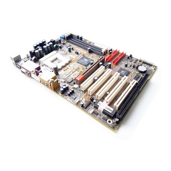
Page 10: 1-14.1 Motherboard Layout
75KAV/75KAV-X 1-14.1 MOTHERBOARD LAYOUT --- 75KAV • Default Setting: 100MHz CPU External clock. FAN1 5 4 3 2 1 4 3 2 1 ATX POWER SSF1 JP10 SOCKET A JP11 Clock Generator KT-133A COM 2 AGP PRO 4x IDE1 CD_IN2 PCI 1 CD_IN1 AC'97... -
Page 11: 1-14.2 Motherboard Layout
75KAV/75KAV-X 1-14.2 MOTHERBOARD LAYOUT --- 75KAV-X • Default Setting: 100MHz CPU External clock. FAN1 5 4 3 2 1 4 3 2 1 ATX POWER SSF1 JP10 SOCKET A JP11 Clock Generator KT-133A COM 2 AGP PRO 4x IDE1 CD_IN2 PCI 1 CD_IN1 AC'97... -
Page 12: Chipset Diagram
75KAV/75KAV-X 1-15 CHIPSET DIAGRAM--- 75KAV/75KAV-X • The KT-133A / VT8363A and VT82C686B chipset is a high performance, cost-effective and energy efficient system controller for the implementation of AGP / PCI / ISA desktop personal computer system based on 64-bit Socket-A (AMD Athlon) processors. SYSCLK, SYSCLK# Athlon INTR, NMI, SMI#, STPCLK#,... -
Page 13: Chapter 2 Hardware Setup
75KAV/75KAV-X CHAPTER 2 HARDWARE SETUP 2-1 CPU INSTALLATION WARNING: • Make sure that +5V DVC and +3.3 DVC capabilities of your power supply are suitable for the processor. • Any attempt to operate the AMD Athlon or Duron processor without a suit- able cooling Fan will result in permanent damage to the processor and potentially other component within the system. - Page 14 75KAV/75KAV-X 3. Make sure that the CPU position in the socket tightly, and then put the lever down to complete the CPU installation.
-
Page 15: Memory Installation
75KAV/75KAV-X 2-2 MEMORY INSTALLATION WARNING!!! • Make sure that you unplug your power supply when adding or remov- ing memory modules or other system components. Failure to do so may cause severe damage to both your mainboard and expansion cards. •... - Page 16 75KAV/75KAV-X FAN1 5 4 3 2 1 4 3 2 1 ATX POWER SSF1 JP10 SOCKET A JP11 Clock Generator NOTICE : When LED “ZD1” light is on , meaning KT-133A that 3.3V is operating COM 2 and flowing into DIMM AGP PRO 4x IDE1 slots, please do not...
-
Page 17: Accelerated Graphics Port(Agp) Pro Installation
75KAV/75KAV-X 2-3 ACCELERATED GRAPHICS PORT(AGP) PRO INSTALLATION • The AGP Pro connector is an extension of the existing AGP connec- tor and it accepts existing AGP cards. AGP Accelerator AGP Pro slot blockader Accelerated Graphics Port (AGP) Pro Slot 20-pin bay Rib(inside slot) 28-pin bay Rib(inside slot) CAUTION!! -
Page 18: Hdd / Fdd Installation
75KAV/75KAV-X 2-4 HDD / FDD INSTALLATION • To install HDD (Hard Disk Drive), you may connect the cable’s blue connector to the motherboard’s primary (IDE1) or secondary IDE connector, and then connect the gray connector to your slave device and the black connector to your master device.If you install two hard disks , you must configure the second drive to Slave mode by setting its jumper accordingly.Please refer to your hard disk documentation for the jumper settings. -
Page 19: Amd Socket 462 Processor Marking Identification
75KAV/75KAV-X 2-5 AMD SOCKET 462 PROCESSOR MARKING IDENTIFICATION • The following figures and tables describe the product marking for the PGA (Socket A) versions of the AMD Athlon Model 4 processor and AMD Duron processor... XXXXXXXXXXX XXXXXXXXXXXX XXXXXXX XXXXXXXXX XXXXXXXXXXX XXXX AMD XXXX Family/Architecture:... -
Page 20: Cpu External Frequency Setting
75KAV/75KAV-X 2-6 CPU EXTERNAL FREQUENCY SETTING CPU EXTERNAL CLOCK PCI CLOCK FSB CLOCK 100MHz 200MHz 33.3MHz (default) 103MHz 34.3MHz 206MHz 210MHz 105MHz 35.0MHz 110MHz 36.7MHz 220MHz 112MHz 37.3MHz 224MHz 115MHz 38.3MHz 230MHz 120MHz 40.0MHz 240MHz 124MHz 31.0MHz 248MHz 133.3MHz 33.3MHz 266MHz 140MHz 35.0MHz... -
Page 21: Bus Ratio Select
75KAV/75KAV-X 2-7 BUS RATIO SELECT • The AMD Athlon and Duron processor provides four Frequency ID signals (FID) to the system controller to indicate the SYSTCLK multiplier at which the processor core operates, This mechanism is automatic. The board maker does not guarantee “Bus Ratio” can be selected if the processor does not support it. - Page 22 75KAV/75KAV-X SW2 DIP1 ~ DIP4 SETTING 5.0x 5.5x 6.0x 6.5x 7.0x 7.5x 8.0x 8.5x 9.0x 9.5x 11.0x 10.0x 10.0x 11.5x 12.0x 11.5x 12.5x...
-
Page 23: Jumper Definitions
75KAV/75KAV-X 2-8 JUMPER DEFINITIONS • The figure below shows the location for the motherboard’s jumper blocks. CAUTION • Do not move the jumper with the power on. Always turn off the power and unplug the power cord from the computer before changing the jumper. Otherwise, the motherboard could be damaged. -
Page 24: 2-8.3 Factory (Jp3)
75KAV/75KAV-X 2-8.2 USB PORT SELECT (JP1/JP2) JP1/JP2: USB PORT SELECT Redirect USB port 3 to USB 2 connector (default) Redirect USB port 3 to AGP 2-8.3 FACTORY (JP3) JP3: FACTORY TEST Only for factory test. 2-8.4 POWER LOST RESUME (JP7) JP7: POWER LOST RESUME Normal (default) Enabled... -
Page 25: 2-8.2 Usb Port Select (Jp1/Jp2)
75KAV/75KAV-X 2-8.6 MEMORY MODULE VOLTAGE SELECT (JP10/JP11) JP10/JP11: MEMORY MODULE VOLTAGE SELECT JP10 3.3V (default) JP11 JP10 3.4V JP11 JP10 3.5V JP11 JP10 3.6V JP11 This function allows you to select the voltage supplied to the DRAM. The default voltage (3.3V) should be used unless processor overclocking requires a higher voltage. -
Page 26: 2-8.8 Wake On Lan Function (Wol1)
75KAV/75KAV-X 2-8.8 WAKE ON LAN FUNCTION (WOL1) WOL1 : WAKE ON LAN (WOL) FUNCTION Connect the Wake On LAN signal from LAN card WOL1 to WOL1 +5V standby This connector connects to a LAN card with a Wake On LAN output. -
Page 27: 2-8.10 Thermal Sensor Connector (Rt2)
75KAV/75KAV-X 2-8.10 THERMAL SENSOR CONNECTOR (RT2) RT2: THERMAL SENSOR CONNECTOR a: Connect to RT2. b: Connect this thermal sensor to particular device which generates lots of heat such as Hard Driver, VGA chip, etc. When connected, user could observe the temperature change from the BIOS program. -
Page 28: Connectors
75KAV/75KAV-X 2-9 CONNECTORS • In this section we list all external connectors that user will use them. 2-9.1 J3 AND J4 1 2 3 4 5 6 7 8 9 10 11 12 13 14 15 HDD LED CONNECTOR PIN 1 Logic High (+) PIN 2 HDD LED SIGNAL... - Page 29 75KAV/75KAV-X 1 2 3 4 5 6 7 8 9 10 11 12 13 14 15 ATX POWER SWITCH PIN 12 ATX POWER SWITCH PIN 13 The system power is controlled by a momentary switch connected to this lead. Pressing the button once will switch the system between ON and SOFT OFF.
- Page 30 75KAV/75KAV-X 1 2 3 4 7 8 9 10 11 12 13 14 15 RESET SWITCH CONNECTOR PIN 5 RESET SIGNAL PIN 6 RESET SWITCH connector connects to the case- mounted reset switch for rebooting your system DESCRIPTION without having to turn off your power switch. This is a preferred method of reboot to prolong the life of the system's power supply.
-
Page 31: 2-9.2 Chassis Panel Connector
75KAV/75KAV-X A1 : 1st HDD LED A2 : 2nd HDD LED A1 A2 B : INFRARED (IR) C : POWER SWITCH D : None E : SPEAKER F : RESET SWITCH G : POWER LED H : NONE : SUSPEND LED 2-9.2 CHASSIS PANEL CONNECTOR A : PS/2 MOUSE PORT B : USB O PORT... -
Page 32: 2-9.3 Atx Power Supply Connector
75KAV/75KAV-X 2-9.3 ATX POWER SUPPLY CONNECTOR • This connector connects to an ATX power supply. The plug from the power supply only inserts in an orientation because of the different hole sizes. Find the proper orientation and push down firmly making sure that all pins are aligned. -
Page 33: 2-9.4 Serial Port Connectors
75KAV/75KAV-X 2-9.4 SERIAL PORT CONNECTORS • One serial port is ready for a mouse or other serial devices. A second serial port is available using a serial port bracket connected from the motherboard to an expansion slot opening. FAN1 5 4 3 2 1 4 3 2 1 ATX POWER SSF1... -
Page 34: 2-9.5 Second Usb Connector
75KAV/75KAV-X 2-9.5 SECOND USB CONNECTOR • This connector is for connecting the additional USB cable. It provides you additional two USB ports. User can order the additional USB cable from your motherboard dealer and vender. Additional USB Cable (Optional) Black Black Green Green... -
Page 35: 2-9.7 Irq Description
75KAV/75KAV-X 2-9.7 IRQ DESCRIPTION Function Description Priority IRQ 0 System Timer IRQ 1 Keyboard Controller IRQ 2 Programmable Interrupt IRQ 3 Serial Port (COM 2) IRQ 4 Serial Port (COM 1) IRQ 5 IRQ 6 Floppy Disk Controller IRQ 7 Parallel Port (LPT1) IRQ 8 Real Time Clock (RTC) -
Page 36: 2-9.8 Voice Diagnostic Function
75KAV/75KAV-X 2-9.8 VOICE DIAGNOSTIC FUNCTION----ONLY FOR 75KAV-X • The Voice Diagnostic Function provides user an indispensable assistance on troubleshooting while assembling your computer components. If there is any conflict or other latent problem triggers a boot-up failure, this new VD-TECH technology will voice you realistically where the conflict/problem is, then user can remove the malfunction quickly. - Page 37 75KAV/75KAV-X FAN1 5 4 3 2 1 4 3 2 1 JP4/JP5: VOICE DIAGNOSTIC LANGUAGE SELECT ATX POWER SSF1 Chinese Language JP10 English Language (default) SOCKET A JP11 Clock Generator Japanese Language Spanish Language KT-133A COM 2 AGP PRO 4x IDE1 CD_IN2 PCI 1...
-
Page 38: Chapter 3 Software Setup
75KAV/75KAV-X CHAPTER 3 SOFTWARE SETUP 3-1 ABOUT SUPPORT CD • In support CD, it contains most informations for user’s requirement, such as Acrobat Reader, BIOS, User’s full version Manual, Driver, Hardware Monitor(if motherboard supports this function), Patch, and Utilities etc,. User can browse the CD and get further details in regard of our motherboard. - Page 39 75KAV/75KAV-X Step 5: • Press Next button to continue. Step 6: • Click “Yes” to continue. Step 7: • Press select the checkbox as below: Bus Master PCI IDE Driver AGP VxD Driver VIA Chipset Function’s Registry IRQ Routing Miniport Driver Note: For user who are upgrading VIA Drivers.
- Page 40 75KAV/75KAV-X Step 9: • We recommend user to leave “Enable/ Disable [Ultra] DMA” checkbox empty. NOTE: Whether select this item or not, user needs to enable the Hard Disk DMA function in Control Panel manually. (For further details, please refer to next page) Step 10: •...
- Page 41 75KAV/75KAV-X Step 13: • After all the setup process is finished, please restart your computer by clicking on Finish. bout Hard Disk DMA Function Last but not least, user must enable the Hard Disk DMA function. The process is below: 1.
-
Page 42: Hardware Monitor Installation
75KAV/75KAV-X 3-3 HARDWARE MONITOR INSTALLATION Step 1: • Please put the support CD attached to motherboard into the CD-ROM drive. • When appears a welcome window as left screen, then user should choose “Install Driver” Step 2: • Click on the “VIA Chipset Driver”. Step 3: •... -
Page 43: Ac 97 Audio Codec Installation
75KAV/75KAV-X Step 6: • Press Next button to finish the Hardware Monitor setup process. 3-4 AC 97 AUDIO CODEC INSTALLATION Step 1: • Please put the support CD attached to motherboard into the CD-ROM drive. • When appears a welcome window as left screen, then user should choose “Install Driver”... - Page 44 75KAV/75KAV-X Step 4: • Press Next button to continue. Step 5: • When asking you install or remove the audio driver, please select “Install” and press Next button to continue. Step 6: • It’s recommended for user to restart the computer after the audio driver is finished.
-
Page 45: Chapter 4 Bios Setup
75KAV/75KAV-X CHAPTER 4 BIOS SETUP 4-1 INTRODUCE THE BIOS • BIOS stands for Basic Input Output System. It is sometimes called ROM BIOS because it is stored in a Read-Only Memory(ROM) chip on the motherboard. BIOS is the first program to run when you turn on your computer. -
Page 46: What Is Post
75KAV/75KAV-X lected and configures your computer accordingly. If the battery charge runs too low, the CMOS content will be lost and POST will issue a “CMOS in- valid” or “CMOS checksum invalid” message. If this happens, you may have to replace the battery. After the battery is replaced, the proper set- tings will need to be stored in SETUP. - Page 47 75KAV/75KAV-X “AWDFLASH.EXE” is a Flash EPROM Programming utility that up dates the BIOS by uploading a new BIOS file to the programmable flash ROM on the motherboard, This program only works in pure DOS environment, the utility can not be worked in win95/98, ME, NT or WINDOWS 2000 environment. Upgrading the system BIOS Set 1.
- Page 48 75KAV/75KAV-X Award Flash Memory Writer Start Screen Award Flash Memory Writer Complete Screen...
- Page 49 75KAV/75KAV-X The parameters of AWDFLASH.EXE /sn: No original BIOS backup /py: Program flash memory /cc: Clear CMOS data after programming NOTE: User can type AWDFLASH /? to get further details about parameters. Wrong usage of parameter will damage the BIOS information, so that we strongly recommend user to leave parameters away unless you realize their function.
-
Page 50: Cmos Setup Utility
75KAV/75KAV-X 4-7 CMOS SETUP UTILITY • This motherboard comes with the AWARD BIOS from AWARD Software Inc. Enter the CMOS Setup Utility Main Menu by: 1. Turn on or reboot your system. After a series of diagnostic checks, the following message will appear: PRESS <DEL>... -
Page 51: Standard Cmos Setup
75KAV/75KAV-X 4-8 STANDARD CMOS SETUP • Standard CMOS Setup allows you to record some basic system hardware configuration and set the system clock and error handling. You only need to modify the configuration values of this option when you change your system hardware configuration or the configuration stored in the CMOS memory gets lost or damaged. - Page 52 75KAV/75KAV-X Date (mm:dd:yy) Set the current date and time. Time (hh:mm:ss) Primary / Secondary This field records the specifications for all non-SCSI Master / Slave hard disk drives installed in your system. Refer to the respective documentation on how to install the drives. Drive A / Drive B Set this field to the type(s) of floppy disk drive(s) in- stalled in your system.
-
Page 53: Advanced Bios Features
75KAV/75KAV-X 4-9 ADVANCED BIOS FEATURES • ADVANCED BIOS FEATURES allows you to improve your system perfor- mance or set up system features according to your preference. Run the ADVANCED BIOS FEATURES as following: 1. Choose “ADVANCED BIOS FEATURES” from the Main Menu and a screen with a list of option will appear: 2. - Page 54 75KAV/75KAV-X CMOS Setup Utility - Copyright (C) 1984-2000 Award Software Advanced BIOS Features Item Help Virus Warning Disabled Menu Level CPU Internal Cache Enabled External Cache Enabled CPU L2 Cache ECC Checking Enabled Quick Power On Self Test Enabled First Boot Device Floppy Second Boot Device HDD-0...
- Page 55 75KAV/75KAV-X Virus Warning Enabled: Activates automatically when the system boots up causing a warning message to appear if there is anything attempting to access the boot sector or hard disk parti- tion table. Disabled: No warning message will appear when there is something attempting to access the boot sector or hard disk partition table.
- Page 56 75KAV/75KAV-X Boot Up NumLock Choose ON or OFF. This option lets user activates Status the NumLock function at boot-up. Gate A20 Option Choose Normal or Fast. This option allows the RAM to access the memory above 1MB by using the fast gate A20 line.
-
Page 57: Advanced Chipset Features
75KAV/75KAV-X 4-10 ADVANCED CHIPSET FEATURES • ADVANCED CHIPSET FEATURES allows you to change the values of chipset registers. These registers control the system options. Run the ADVANCED CHIPSET FEATURES as following: 1. Choose “ADVANCED CHIPSET FEATURES” from the Main Menu and a screen with a list of option will appear: 2. - Page 58 75KAV/75KAV-X CMOS Setup Utility - Copyright (C) 1984-2000 Award Software Advanced Chipset Features Item Help Menu Level DRAM Timing By SPD Enabled DRAM Clock 100MHZ SDRAM Cycle Length Disabled Bank Interleave DRAM Drive Strength Auto DRAM Drive Value Memory Hole Disabled PCI Master Pipeline Req Enabled...
- Page 59 75KAV/75KAV-X DRAM Timing by SPD This item allows you to select DRAM Timing by SPD or not. SPD (Serial Presence Detect) you can find it located on your memory modules, BIOS reads information coded in SPD during system boot up resulting in a accurate memory operation.
- Page 60 75KAV/75KAV-X System BIOS Choose Enabled or Disabled. When enabled, the Cacheable access to the system BIOS ROM addressed at F0000H - FFFFFH is cached. Video RAM Cacheable Choose Enabled or Disabled. When enabled, the access to the VGA RAM addressed is cached. AGP Aperture Size Choose 4, 8, 16, 32, 64, 128 or 256 MB.
- Page 61 75KAV/75KAV-X CPU to PCI Write When this field is Enabled, writes from the CPU to Buffer the PCI bus are buffered, to compensate for the speed differences between the CPU and the PCI bus. When Disabled, the writes are not buffered and the CPU must wait until the write is complete before starting another write cycle.
-
Page 62: Integrated Peripherals
75KAV/75KAV-X 4-11 INTEGRATED PERIPHERALS • INTEGRATED PERIPHERALS option allows you to get some informations inside your system when it is working. Run the INTEGRATED PERIPHERALS as following: 1. Choose “INTEGRATED PERIPHERALS” from the Main Menu and a screen with a list of option will appear: CMOS Setup Utility - Copyright (C) 1984-2000 Award Software Integrated Peripherals Item Help... - Page 63 75KAV/75KAV-X 2. Use one of the arrow keys to move between options and modify the se- lected options by using PgUp / PgDn / + / - keys. An explanation of the <F> keys follows: <F1>: “Help” gives options available for each item. <Shift>...
- Page 64 75KAV/75KAV-X OnChip IDE Channel 0/ The chipset contains a PCI IDE interface with sup- port from two IDE channels. Select Enabled to acti- vate the first and/or the second IDE interface. Select Disabled to deactivate an interface if you install a pri- mary and/or second add-on IDE interface.
- Page 65 75KAV/75KAV-X Onboard FDC Select Enabled if your system has a floppy drive con- Controller troller (FDC) installed on the system board and you want to use it. If you install add-in FDC or the system has no floppy drive, select Disabled in this field. The choice: Enabled, Disabled.
- Page 66 75KAV/75KAV-X Parallel Port EPP Type Select EPP port type 1.7 or 1.9 The choice: EPP1.7, 1.9. Onboard Legacy Audio This field controls the onboard audio. • Sound Blaster • SB I/O Base Address • SB IRQ Select • SB DMA Select •...
-
Page 67: Power Management Setup
75KAV/75KAV-X 4-12 POWER MANAGEMENT SETUP • POWER MANAGEMENT SETUP allows you to set the system’s power saving functions. Run the POWER MANAGEMENT SETUP as following: 1. Choose “POWER MANAGEMENT SETUP” from the Main Menu and a screen with a list of option will appear: CMOS Setup Utility - Copyright (C) 1984-2000 Award Software Power Management Setup ACPI Function... - Page 68 75KAV/75KAV-X ACPI Function Enabled: Turn on ACPI function. Disabled: Turn off ACPI function. • Press <Enter> on the Power Management item, then there is a list of it appears for you to choose further setting. CMOS Setup Utility - Copyright (C) 1984-2000 Award Software Power Management Power Management User Define...
- Page 69 75KAV/75KAV-X ACPI Suspend Type This item will allow you to select the ACPI suspend type. You can select S3(STR) for suspending to DRAM or S1(POS) for power on suspend under Windows 98 ACPI mode. The choice: S1(POS), S3(STR). PM Control by APM When enabled, an Advanced Power Management device will be activated to enhance the Max.
- Page 70 75KAV/75KAV-X Soft-Off by PWRBTN Instant-Off: Turn off the system power at once after pushing the power button. Delay 4 Sec: Turn off the system power 4 seconds after pushing the power button. (to meet PC97/98 spec) • Press <Enter> on the Wake Up Events item, then there is a list of it appears for you to choose further setting.
- Page 71 75KAV/75KAV-X Wake Up On LAN/Ring An input signal on the serial Ring Indicator (RI) line (in other words, an incoming call on the modem) awak- ens the system from a soft off state. The choice: Enabled, Disabled. RTC Alarm Resume When Enabled, you can set the data and time at the which the RTC (Real Time Clock) alarm awakens the system from suspend mode.
- Page 72 75KAV/75KAV-X CMOS Setup Utility - Copyright (C) 1984-2000 Award Software IRQ Activity Monitoring IRQ 3 (COM2) Enabled Item Help IRQ 4 (COM1) Enabled Menu Level IRQ 5 (LPT2) Enabled IRQ 6 (Floppy Disk) Enabled IRQ 7 (LPT1) Enabled IRQ 8 (RTC Alarm) Disabled IRQ 9 (IRQ2 Redir) Disabled...
-
Page 73: Pnp / Pci Configuration
75KAV/75KAV-X 4-13 PNP / PCI CONFIGURATION • PNP/PCI CONFIGURATION allows you to set the system’s power saving functions. Run the PNP/PCI CONFIGURATION as following: 1. Choose “PNP/PCI CONFIGURATION” from the Main Menu and a screen with a list of option will appear: CMOS Setup Utility - Copyright (C) 1984-2000 Award Software PnP/PCI Configurations PNP OS Installed... - Page 74 75KAV/75KAV-X PNP OS Installed Yes: OS supports Plug and Play function. No: OS doesn’t support Plug and Play function. NOTE: BIOS will automatically disable all PNP resources except the boot device card when you select Yes on Non-PNP operating system. Reset Configuration Choose Enabled or Disabled.
- Page 75 75KAV/75KAV-X DMA Resources Press Enter. Please refer to the below list. CMOS Setup Utility - Copyright (C) 1984-2000 Award Software DMA Resources DMA-0 assigned to PCI/ISA PnP Item Help DMA-1 assigned to PCI/ISA PnP Menu Level DMA-3 assigned to PCI/ISA PnP DMA-5 assigned to PCI/ISA PnP DMA-6 assigned to...
-
Page 76: Pc Health Status
75KAV/75KAV-X 4-14 PC HEALTH STATUS • This section helps you to get more information about your system including CPU temperature, FAN speed and voltage. It is recommended that you contact with your motherboard supplier to get proper value about your set- ting of the CPU temperature. -
Page 77: Frequency/Voltage Control
75KAV/75KAV-X 4-15 FREQUENCY/VOLTAGE CONTROL CMOS Setup Utility - Copyright (C) 1984-2000 Award Software Frequency Control Item Help Auto Detect DIMM/PCI Clk Enabled Spread Spectrum Modulated Disabled Menu Level CPU Host/PCI Clock Default Method In Linear Funct. Increase CPU HOST By Linear Funct. CPU Voltage Regulator Default :Move Enter:Select +/-/PU/PD:Value F10:Save ESC:Exit F1:General Help... -
Page 78: Load Optimized Defaults
75KAV/75KAV-X CPU Voltage Regulator This item allows user to adjust the CPU Vcore voltage. The instant damage of CPU is due to the wrong Vcore voltage setting, so that we recommend that user should leave this item with Default setting unless you know how to adjust it. -
Page 79: Set Supervisor / User Password
75KAV/75KAV-X 4-17 SET SUPERVISOR / USER PASSWORD • These two options allow you to set your system passwords. Normally, the supervisor has a higher ability to change the CMOS setup option than the user. The way to set up the passwords for both Supervisor and User are as follows: 1. -
Page 80: Save & Exit Setup
75KAV/75KAV-X 4-18 SAVE & EXIT SETUP • SAVE & EXIT SETUP allows you to save all modifications you have speci- fied into the CMOS memory. Highlight this option on the Main Menu and the following message appears: “SAVE to CMOS and EXIT (Y/N) ? Y “...
Need help?
Do you have a question about the SL-75KAV and is the answer not in the manual?
Questions and answers