Table of Contents
Advertisement
Quick Links
Advertisement
Table of Contents

Related Manuals for DIGITIZE DDI-10E


Summary of Contents for DIGITIZE DDI-10E
- Page 1 DDI-10E DUAL LINE EXTERNAL DIGITAL DIALER RECEIVER MODULE INSTALLATION OPERATION MANUAL Digitize, Inc. 158 Edison Road Lake Hopatcong, New Jersey 07849 Tel: (973) 663-1011 Part Number: 700280-0001 Fax: (973) 663-4333 Revision: B http://www.digitize-inc.com Issue Date: 5/11...
- Page 2 Digitize, Inc. 158 Edison Road Lake Hopatcong, NJ 07849-2217 The DIGITIZE logo is a registered trademark of Digitize, Inc...
- Page 3 This manual has been prepared by DIGITIZE, INC. for use by its licensees, distributors and customers. The information contained herein is the property of DIGITIZE, INC. and may not be copied, disclosed or reproduced, in whole or in part, without the prior written approval of DIGITIZE, INC. Any unauthorized disclosure to, or use of the enclosed information by, unauthorized third persons shall void any and all representations, warranties and obligations on the part of DIGITIZE, INC.
- Page 4 FCC NOTICE In compliance with Paragraph 15.105 of the FCC Rules and Regulations, the following notice is provided. NOTE: This equipment has been tested and found to comply with the limits for a Class A digital device, pursuant to Part 15 of the FCC Rules. These limits are designed to provide reasonable protection against harmful interference when the equipment is operated in a commercial environment.
-
Page 5: Table Of Contents
4.2.3 C LED) ....................4-4 OMPUTER MBER 4.2.4 P LED) ....................4-4 RINTER MBER 4.3 REDUNDANT OPERATION ....................4-4 5 DDI-10E SETUP................5-1 5.1 W III ..................5-1 XPRECIUM XPRECIUM 5.1.1 W II ......................5-1 XPRECIUM 5.1.2 T III......................5-1 XPRECIUM 5.1.3 C... -
Page 7: Overview
The DDI-10E is a dual line external dialer receiver module capable of processing a variety of dialer protocols as noted in this manual. Only one DDI-10E may be connected to a SYSTEM 3505, thus permitting two incoming phone lines to be monitored. Consult... -
Page 8: Caller Id
DDI-10E processes the data. The DDI-10E card processes dialer Alarm, Trouble and Restore conditions. SYSTEM 3505 displays and prints the incoming DDI-10E signals. The user can specify Restoral = Yes or No for each account number. After an alarm or trouble condition appears, the CLEAR button will blink if an invalid account number comes through or if Restoral = N for that account number. -
Page 9: Mem-Id
DDI-10E recommends .5AH x desired standby time. Digitize supplies a two-foot red and black wire with a connector on one end for the DDI-10E and another to plug into the AUX power output on the rear of the SYSTEM 3505. Since the DDI-10 is powered through the System 3505, the DDI-10 will also use the battery backup that the System 3505 uses. -
Page 10: Selected Set Menu Options
DDI-10E INSTALLATION AND OPERATION MANUAL 1.7 SELECTED SET MENU OPTIONS Some of the SET MENU selections apply to the DDI-10E while other settings only apply to the DDI-9E and the Intellitize radio system. The latter two are included in this manual as they are part of the DDI-10E SET MENU selections. -
Page 11: Dialer Set Up
(16) and pressing the SET button. When using the DDI-10E with Contact ID format, the only information that must be set up using the 16 SET menus is the customer number and whether the DDI-10E reports in 24 hours or less often. -
Page 12: Main Menu
DDI-10E INSTALLATION AND OPERATION MANUAL The factory default password is 2222. Password can be changed via the keyboard. Refer to the Password Menu in the SYSTEM 3505 Installation and Operation Manual for more detail. If the password for this level has already been changed, enter the new password. -
Page 13: Configuration Tables
DDI-10E INSTALLATION AND OPERATION MANUAL Please note: When selecting and setting up Configuration Tables, keep in mind that the operator has the ability to copy any configuration to another configuration. 2.2 CONFIGURATION TABLES The System 3505 is shipped with Configurations 1 and 2 set at factory default settings. -
Page 14: Translate Alarm Codes To Zones
DDI-10E INSTALLATION AND OPERATION MANUAL 2.3 TRANSLATE ALARM CODES TO ZONES To change the default settings on Configuration 1 or 2 or to set up new Configuration Tables, enter 1 (ZONE) and the display will read: The cursor is on the first field (CONFIG # ). -
Page 15: Set English Equivalents
DDI-10E INSTALLATION AND OPERATION MANUAL In addition, during initialization the SYSTEM 3505 will print an error message if it discovers duplicate zones. When all zone data is entered, press CLEAR to return to the Set Up Mode screen. At this time the English Equivalents should be set. Press FUNC to select Cust/Config screen. -
Page 16: Opening And Closing Codes
DDI-10E INSTALLATION AND OPERATION MANUAL 2.5 O PENING AND LOSING ODES The use of a zero in the second digit allows 16 Openings/Closings to be monitored. Table 7.3.2.(a)- Configuration # 1 Zone Factory Default Settings ZONE * If a zone number is not used in a configuration, the System 3505 will skip a line when it prints the table. - Page 17 DDI-10E INSTALLATION AND OPERATION MANUAL Table 7.3.2.(b) - Configuration #1 English Equivalent Factory Default Settings PROCESS DAILY TEST SECURE ALL OPENING CLOSING AC FAILURE AC NOW OK LINE 1 FAULT LINE 1 OK GROUND FAULT GND NOW OK BATTERY FAIL...
-
Page 18: Configuration Table Details
Once all Configuration tables have been set up, Customer Numbers can be added to the system. Customer numbers are three to six digit numbers that will represent the Dialer Account number calling in to the DDI-10E. Do NOT include Zone numbers in the customer number. - Page 19 DDI-10E INSTALLATION AND OPERATION MANUAL Select ADD/24HR/CONFIG/RESTORE, Enter desired CUSTOMER Number (i.e., 1234). DO NOT INCLUDE ZONE #. Press SET to ADD or DELETE selection. Press PRINT for CUSTOMER list. After the operator enters the Customer number and presses the SET button the printer...
- Page 20 DDI-10E INSTALLATION AND OPERATION MANUAL The fourth line of the display will read “SEE PRINTOUT” and an audible Trouble buzzer will sound. To silence the buzzer the operator must press “CLEAR”. The following message will print when the first dialer is missed:...
-
Page 21: Set Up Configuration Tables (Translations)
DDI-10E INSTALLATION AND OPERATION MANUAL Use ↑↓ keys to change RESTORE = Y or N. Y = Dialer will send restoral. When all customer numbers have been entered, press CLEAR to return to the SET UP MODE screen. At this time the Dialer Handshake should be set. Press FUNC to select the CUST/CONFIG screen. -
Page 22: Copy One Config Table To Another
DDI-10E INSTALLATION AND OPERATION MANUAL 2.8.3 Copy one config table to another At the CUST/CONFIG screen, Enter 3 (COPY) and the display will read: Press the FUNC button to move to the next field (TO). If the FROM and TO Configuration Numbers are correct, and SET is pressed, the printer... -
Page 23: Convert Sia Designators To Contact Id Text
DDI-10E INSTALLATION AND OPERATION MANUAL 2.8.4 Convert SIA designators to Contact ID text The DDI-10E can process SIA dialer types. The SYSTEM 3505 processes the SIA dialers by converting the event to a CID protocol. Use the WIN3505 utility to edit the CID tables and insert the desired SIA representation to be converted to CID. -
Page 24: Force A Daily Test After The Following
2.8.7 Rings to Answer the Phone The default setting is 1 ring. For certain applications, a backup DDI-10E with parallel phone lines to the primary DDI-10E would be set up to answer the phone on the second or third ring at a remote SYSTEM 3505. -
Page 25: On The Fly Zone Conversion
DDI-10E INSTALLATION AND OPERATION MANUAL 2.8.8 On the Fly Zone Conversion If you have dialer accounts where there is one or two zone variations from a Configuration table, and you do not want to assign another configuration table to accommodate this difference, you can use the “On the Fly Zone Conversion” to convert several of those dialer account zones to conform with the standard assigned config table. - Page 26 Exprecium software to set up the handshake requirements in the DDI-10E as noted in section 5. The DDI-10E can use the Caller ID to select the proper first handshake to use based on previous experience with the handshake that the dialer responded to previously.
-
Page 27: Retrofits
DDI-10E setup is performed by connecting a PC and running a Windows setup utility, WIN Exprecium as supplied with the DDI-10E and noted in Section 5, to make the selections. Certain changes are made by the 3505 to the DDI-10E. -
Page 29: Operation
The SYSTEM 3505 prints the actual code message it receives as an alarm. The third line of the message is the actual data transmitted to the DDI-10E. ‘RAW’ indicates the information to follow is the actual code received. The ‘1’ indicates the protocol used to decode the message. -
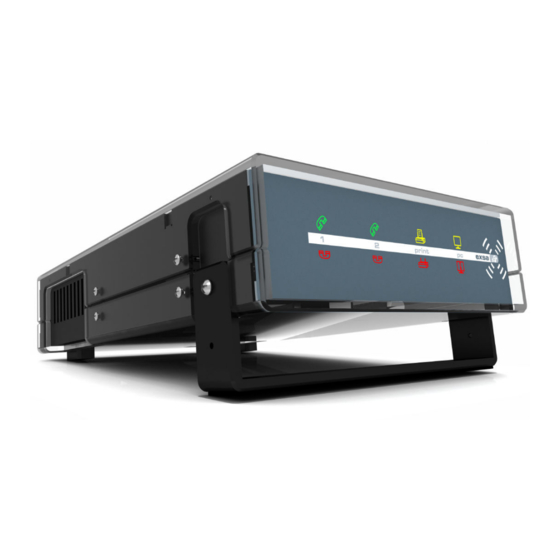
Page 30: Ddi-10E Front And Rear View
DDI-10E INSTALLATION AND OPERATION MANUAL A typical SECURE sequence is depicted on the thermal printer message below: SECURE DD 121-F9 Secure BATTERY OK Condition Secured 03 JUN 95 16:24:35 Date and Time RAW 1 DD #1 121-E9 Actual Data Sent to SYSTEM 3505 From Digital Dialer 4.1 DDI-10E F... -
Page 31: Led Indicators
Line 1 and Line two LED’s flashing alternately indicates SYSTEM 3505 commanded DDI-10E not to answer the phone. This feature is used when redundant SYSTEM 3505 are in service (i.e. one DDI-10E is on line, while the backup DDI-10E is off Line). 700280-0001 Rev. A 11/09 Digitize, Inc. -
Page 32: Computer (Amber Led)
DDI-10E can be installed on each of the redundant units. The online unit will answer the phone. The backup unit will be in standby. Both DDI-10E units will have the phone lines in parallel. Or, one dual-line DDI-10E may be used between the redundant SYSTEM 3505 units. -
Page 33: Ddi-10E Setup
Example shown here 2.0.1d WARNING! If new firmware is installed the DDI-10 settings Must be Re-configured. The “D” in V2.0.1 D is the indication of a Digitize version program. 700280-0001 Rev. B 5/11 Digitize, Inc. -
Page 34: Configuration Settings Information
4 ring, 3-2 instead of 4-1 etc. Customers will also have the ability to re-configure their DDI-10 in the field should the Digitize Factory default settings need to be changed. 5.1.4 Digitize Factory Default Settings The Factory Default Settings have been chosen based on knowledge from previous receiver setting in many of our installations and input from MCDI. - Page 35 DDI-10E INSTALLATION AND OPERATION MANUAL 700280-0001 Rev. A 11/09 Digitize, Inc. Specifications Subject to Change Without Notice...
-
Page 36: Using Your Pc To Connect To The Ddi-10 With Exprecium Iii
5.1.6 Using your PC to connect to the DDI-10 with Exprecium III Exprecium III can be used to see the current Full Version of the firmware installed in the DDI-10E. Exprecium III can also be used to view the current configuration settings or to load new firmware in the DDI-10E. - Page 37 DDI-10E INSTALLATION AND OPERATION MANUAL To use a PC to view dialer data check the box “Enable” under Acknowledge. The PC can now be used to monitor and troubleshoot the dialer data directly from the DDI-10E. 700280-0001 Rev. A 11/09 Digitize, Inc.
-
Page 38: View Configuration Settings In Win We Xprecium Iii
DDI-10E INSTALLATION AND OPERATION MANUAL 5.1.8 View configuration settings in WinWExprecium III From the main screen click on “Configure Parameters” The settings in this sample are for a standard default. Use the WinExprecium II to change the DDI-10 settings. Digitize, Inc. - Page 39 FCC INFORMATION The DDI-10E connects to the telephone line by means of a standard jack (USOC RJ11 C or USOC RJ45 S). Connection to telephone company coin operated service (central office implemented system) is prohibited. Connection to party line service is subject to State tariffs.
- Page 40 DDI-10E INSTALLATION AND OPERATION MANUAL Zone Settings Worksheet Configuration # ___________ ZONE ALM TRB ZONE ALM TRB ZONE ALM TRB Digitize, Inc. 700280-0001 Rev. B 5/11 Specifications Subject to Change Without Notice...
- Page 41 DDI-10E INSTALLATION AND OPERATION MANUAL English Equivalent Worksheet Configuration # _______________ PROCESS DAILY TEST SECURE ALL OPENING CLOSING AC FAILURE AC NOW OK LINE 1 FAULT LINE 1 OK GROUND FAULT GND NOW OK BATTERY FAIL BATTERY OK LINE 2 FAULT...
- Page 43 APPENDIX A CONTACT ID CODES DDI-10E MANUALCONTACT ID CODES Digitize Event Log Line 1 Line 2 Line 3 Notes Prior Lev ALM LV6 Medical Personal Emerg. ALM LV6 Medical Pendant Transmit ALM LV6 Medical Fail To Check In FIRE Fire Alarm...
- Page 44 DDI-10E INSTALLATION AND OPERATION MANUAL Digitize Event Log Line 1 Line 2 Line 3 Notes Prior Lev ALM LV7 24 Hr. Non Burglary Tank Level FA SUPV. Fire Supervisory Fire Supervisory FA SUPV. Fire Supervisory Low Water Pressure FA SUPV.
- Page 45 DDI-10E INSTALLATION AND OPERATION MANUAL Digitize Event Log Line 1 Line 2 Line 3 Notes Prior Lev TROUBLE Communication Trbl LR Radion Xmitter Fault TROUBLE Communication Trbl, Failure to Communicate TROUBLE Communication Trbl, Loss of Radio Supervision TROUBLE Communication Trbl, Loss of...
- Page 46 DDI-10E INSTALLATION AND OPERATION MANUAL Digitize Event Log Line 1 Line 2 Line 3 Notes Prior Lev BURGLARY Open/Close Wrong Code Data (No Restore) BURGLARY Open/Close Legal Code Entry (No Restore) BURGLARY Open/Close Re-arm After Alarm (No Restore) BURGLARY Open/Close...
- Page 47 The SIA conversion table is not available at this time: TROUBLE Unknown type for this SIA message IMPORTANT NOTICE: DIGITIZE, INC. products should be tested every month (under no circumstances less than every three months) to insure complete and proper operation and proper input and output connections.
- Page 48 Digitizes option, the part or parts of the products which prove defective in material or workmanship for 12 months within 15 months after shipment by Digitize. Buyer must pass along to its initial customer or user ("Customer") a minimum of 12 months’ coverage within the 15-month warranty period, provided the Buyer gives Digitize prompt notice of any defect and satisfactory proof thereof.
Need help?
Do you have a question about the DDI-10E and is the answer not in the manual?
Questions and answers