Table of Contents
Advertisement
Quick Links
Advertisement
Table of Contents

Related Manuals for Multitech MultiFRAD FR221


Summary of Contents for Multitech MultiFRAD FR221
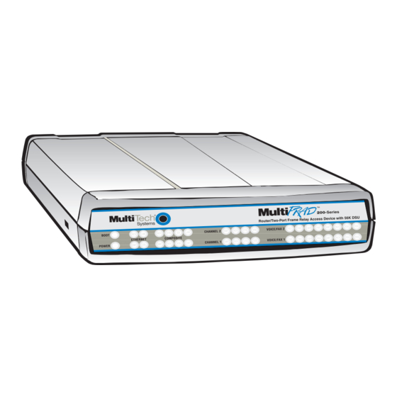
- Page 1 MultiFRAD 200-Series Models FR221 & FR221/V2 User Guide...
- Page 2 Furthermore, Multi-Tech Systems, Inc. reserves the right to revise this publication and to make changes from time to time in the content hereof without obligation of Multi-Tech Systems, Inc. to notify any person or organization of such revisions or changes.
-
Page 3: Table Of Contents
Unpacking your MultiFRAD ... 15 Cabling your MultiFRAD ... 16 V.35 Shunt Procedure ... 18 E&M Jumper Block Positioning Procedure (FR221/V2 Only) ... 20 Chapter 3 - Software Loading and Configuration Installing Your Software ... 22 Ethernet Setup ... 25 WAN Port Setup ... - Page 4 Changing Channel Parameters (FR221/V2 only) ..64 Interface ... 64 Voice/Fax (FR221/V2 only) ... 66 Regional (FR221/V2 only) ... 67 Changing the Phone Directory Database (FR221/V2 only) ... 68 Others Setup ... 70 Chapter 5 - Remote Configuration and Management Introduction ... 74 Remote Configuration ...
-
Page 5: Chapter 1 - Introduction And Description
Chapter 1 - Introduction and Description... -
Page 6: Introduction
To access this free voice and fax communication, all you have to do is connect the FR221/V2 to your telephone equipment and then to your frame relay connection. Once configured, the FR221/V2 allows voice and fax to travel down the same path as your traditional data communications. -
Page 7: Preview Of This Guide
Chapter 6 provides instructions on getting service for your MultiFRAD at the factory, a statement of the limited warranty, information about our user bulletin board service, and space for recording information about your MultiFRAD prior to calling Multi-Tech’s Technical Support personnel. -
Page 8: Front Panel Description
Front Panel Description The front panel of the FR221 has four groups of LEDs that provide the status of the LAN connection and the general status of the MultiFRAD. The FR221/V2 has an additional group of LEDs for its two voice/fax channels. - Page 9 VOICE/FAX CHANNELS (FR221/V2 Only) Foreign Exchange Station indicator lights when the voice/fax Channel is configured for FXS operation. Foreign Exchange Office indicator lights when the voice/fax Channel is configured for FXO operation. E&M Ear and Mouth indicator lights when the voice/fax Channel is configured for E&M operation.
-
Page 10: Back Panel Description
The back panel connectors are shown in Figure 1-3 and described in the following groups. Figure 1-3. Back Panel (FR221/V2) Voice/Fax Channel 1 and 2 (on FR221/V2 only) The Voice/Fax Channel connectors include three options per Channel: E&M, FXO and FXS. -
Page 11: Shunts
Shunts There are three shunts (Figure 1-4) on the printed circuit board for the composite link trunk connection and the two data Channels. Trunk RS232 Shunt Position Trunk V.35 Shunt Position Channel 1 V.35 Shunt Position Channel 2 V.35 Shunt Position Figure 1-4. -
Page 12: Technical Specifications
MultiFRAD User Guide Technical Specifications The MultiFRAD conforms to the following specifications: • Provides access to Frame Relay Networks for IP, IPX, bridged LAN traffic, Async and HDLC Sync devices • DSU Port - 56 Kbps, synchronous • Data ports can be configured as either EIA-232 or V.35 •... -
Page 13: Chapter 2 - Installation
Chapter 2 - Installation... -
Page 14: Introduction
The battery has an estimated life expectancy of ten years. When the battery starts to weaken, the date and time may be incorrect. If the battery fails, the voice/ fax board must be sent back to Multi-Tech Systems for battery replacement. -
Page 15: Unpacking Your Multifrad
(Figure 2-1) before proceeding with the installation. If any item appears to be damaged, do not power up the unit; contact Multi-Tech’s Technical Support personnel for advice (Refer to Chapter 6). If no damage is observed, configure the MultiFRAD using the information in the rest of this chapter. -
Page 16: Cabling Your Multifrad
Cabling your MultiFRAD Cabling your MultiFRAD involves making the proper Power, Command Port, Ethernet, and Channel (and Voice/Fax, FR221/V2 Only) connections. Figure 2-2 shows the back panel connectors and the associated cable connections. The MultiFRAD supports two data channels. Note: Before starting to cable your MultiFRAD (FR221/V2 Only), perform the E&M Jumper Block Positioning Procedure if either voice/fax channel (1 or 2) will be connected to an E&M trunk that is a... - Page 17 On the FR221/V2 only: if you are connecting your MultiFRAD to a station device; e.g., analog telephone, fax machine, or Key Telephone System (KTS); connect one of the supplied RJ-11 cables to the Voice/Fax Channel 1 FXS connector on the back of the MultiFRAD and the other end to the station device.
-
Page 18: V.35 Shunt Procedure
Place the PCB assembly on a flat, grounded surface. Note: For the FR221/V2 only, you will have to remove the voice/fax daughterboard by performing the following steps to gain access to the shunt locations on the main PCB assembly. - Page 19 Repeat step 5 for any other shunt that needs to be moved. Note: For the FR221/V2 only, reinstall the voice/fax daughterboard before replacing the PCB assembly in the cabinet. Check that none of the long pins are bent or out of alignment.
-
Page 20: E&M Jumper Block Positioning Procedure (Fr221/V2 Only)
E&M Jumper Block Positioning Procedure (FR221/V2 Only) Each voice/fax channel on the FR221/V2 has a separate E&M jumper block, located near the channel jacks on the back panel of the MultiFRAD. Each jumper block has 8 pairs of pins with a jumper plug on three adjacent pairs of pins. -
Page 21: Chapter 3 - Software Loading And Configuration
Chapter 3 - Software Loading and Configuration... -
Page 22: Installing Your Software
MultiFRAD User Guide Installing Your Software The following procedure does not provide every screen or option used in the process of installing the MultiFRAD software. The assumption is that a technical person with a thorough knowledge of Windows and the software loading process is doing the installation. Additional information on the MultiFRAD software is provided in the User Guide supplied with your MultiFRAD. - Page 23 After all the program files from both disks are loaded, the Setup dialog box is displayed, enabling you to designate the COM port of the PC that is connected to your MultiFRAD. On the Select Port field, click the down arrow and choose the COM port of your PC (COM1 -- COM4) that is connected to your MultiFRAD.
- Page 24 MultiFRAD User Guide The following message is displayed: Click Yes to continue. 10 If your MultiFRAD is already turned on and fully booted, you may get the following message; if so, click Yes to continue.
-
Page 25: Ethernet Setup
Ethernet Setup 11 If your MultiFRAD is connected to an IPX network, continue with the following steps (12 thru 15). If your MultiFRAD is NOT connected to a LAN, click the IPX Routing Enable check box to disable IPX, then click OK and proceed to step 16 to disable IP protocol. 12 Router Name: You can either use the default Router Name (MultiFRAD 200) or assign a new Router Name in this field. - Page 26 MultiFRAD User Guide 17 Record the IP address protocol information for your specific network in the space provided below: Ethernet IP Address Mask ___.___.___.___ ___.___.___.___ WAN Port IP Address Mask ___.___.___.___ ___.___.___.___ 18 The default Ethernet IP Address has to be changed to your unique LAN address. Enter an acceptable, unique IP address for the Ethernet port.
-
Page 27: Wan Port Setup
Chapter 3 - Software Loading and Configuration WAN Port Setup 23 The WAN Port Setup dialog box is displayed. The defaults are as shown above: Frame Relay connection, Synchronous mode, with external clocking (DDS) from the phone system. Since the DSU connector on your MultiFRAD is cabled to a trunk connection of a frame relay network, click OK. -
Page 28: Data Ports Setup
MultiFRAD User Guide Data Ports Setup 24 The Data Port Configuration dialog box enables you to individually configure the two data channels (Port 1 and Port 2) for PPP/Frame Relay, data over IP, or as a frame relay Hub. The Encapsulation Type group determines how the data channel is configured. -
Page 29: Dlci Setup
Chapter 3 - Software Loading and Configuration DLCI Setup 28 If you enabled Frame Relay in the WAN Ports Default Setup dialog box, the Frame Relay DLCI Default Setup dialog box is displayed with all the groups inactive. Click OK to continue. Note: When your MultiFRAD is connected to an active frame relay network service, it can detect DLCIs and the frame relay management type. -
Page 30: Voice/Fax Channel Setup
MultiFRAD User Guide Voice/Fax Channel Setup 29 The Voice/Fax Channel setup dialog box is displayed. Its three tabs are used to define the voice/fax channel interface, voice coder, fax parameters, and regional phone parameters (tone pairs) for each channel. Configure each channel for the type of interface you are connecting to. The Interface tab defaults to Channel 1 in the Select Channel field. - Page 31 31 Repeat the above step to configure the interface type for voice/fax channel 2. To change the channel number, click the down arrow and highlight Channel 2. 32 When you are satisfied with your interface choices, and if the default voice coder is acceptable and your country/region is the default USA, then you can click OK and continue building your phone directory database.
- Page 32 MultiFRAD User Guide Click OK to continue. 36 The Writing Setup dialog box is displayed as the setup configuration is written to the MultiFRAD. 37 After the setup is written to the MultiFRAD, the unit reboots. 38 Check that the BOOT LED on the MultiFRAD is Off after the download is complete. This may take several minutes as the MultiFRAD reboots.
-
Page 33: Detect And Map Your Dlcis
Detect and Map Your DLCIs 40 To detect DLCIs and map your data ports and protocols to the detected DLCIs, perform the following steps: Win3.1 users - from the Program Manager, click the MultiFRAD Configuration icon in the MultiFRAD 200 Program Group. The main menu is displayed. Win95/98/NT users - from your desktop, click Programs | MultiFRAD 200 | MultiFRAD Configuration. - Page 34 DLCI. 48 Ensure that Throttle Up and Down is selected in the Congestion Management group. 49 Ensure that Adhere to CIR + Be is selected in the Mode group. Multi-Tech recommends using this setting initially.
-
Page 35: Build Your Phone Directory Database
Click OK. 53 The main menu is displayed. Build Your Phone Directory Database Perform the following steps to construct your phone directory database. 54 Click Phone Book on the main menu. The Phone Directory Database dialog box is displayed. You will build your personalized MultiFRAD Phone Directory in the following steps. - Page 36 MultiFRAD User Guide In the Station Information group, enter a unique phone number for the destination voice/fax channel in the Phone Number field. For example, phone number 101. (This number does not have to be a standard number with 7 or more digits.) The Description field for the phone number is optional.
- Page 37 57 Repeat steps 55 and 56 for each additional phone number. You should enter one phone number for each remote channel that you want to call. When you are finished, click OK. 58 You are returned to the main menu. Click Download Setup.
- Page 38 MultiFRAD User Guide...
-
Page 39: Chapter 4 - Multifrad Software
Chapter 4 - MultiFRAD Software... -
Page 40: Introduction
MultiFRAD User Guide Introduction This chapter describes various features of the MultiFRAD software that enable you to change (update) the configuration of your MultiFRAD. The basic configuration parameters were established during the loading of the software described in this chapter enable you to change that initial configuration as necessary. The primary interface to the MultiFRAD software is a main menu (with MultiFRAD v3.00 in the title bar) with individual buttons that enable you to quickly and easily select a desired function. -
Page 41: Multifrad Configuration
Chapter 4 - MultiFRAD Software MultiFRAD Configuration To view or change your MultiFRAD configuration in Windows 95/NT, click Start | Programs | MultiFRAD 200 | MultiFRAD Configuration, or double-click the MultiFRAD Configuration icon in the MultiFRAD 200 program group. After loading, the MultiFRAD main menu will appear. The MultiFRAD main menu consists of 12 buttons in which you can point and click, an Events window, and a status bar. -
Page 42: Changing Ip Parameters
MultiFRAD User Guide Changing IP Parameters The IP Setup dialog box enables you change the IP routing capabilities, add or delete logical WANs, enable the DHCP relay agent, assign DNS server addresses, and define static routes and a default route. The initial routing capabilities were established during the software installation. You can change IP routing parameters by clicking on the Advanced tab and changing, for example, the RIP Response Time or RIP Route Aging Time. - Page 43 Chapter 4 - MultiFRAD Software The Advanced tab on the IP Setup dialog box controls the timers, Dynamic Host Configuration Protocol (DHCP) and Domain Name System (DNS) options, the default route, filters, and Static Routes. In most cases, you should not have to change the value of any timer (default TTL, reassembly time-out, RIP response time, or RIP route aging time).
-
Page 44: Changing Ipx Parameters
MultiFRAD User Guide Changing IPX Parameters The IPX Setup dialog box controls the four frame types and the WAN ports. The Advanced tab enables IPX routing, enables auto learn of Ethernet network numbers, and specifies the distributed name of the MultiFRAD. The RIP and SAP default timers should not have to be changed for most applications. - Page 45 Chapter 4 - MultiFRAD Software The IPX WAN network number has to be the same on both ends of the link and must be unique throughout the internetwork. If the WAN port is configured in a point-to-point operation, both WAN network numbers have to be the same and unique.
-
Page 46: Spanning Tree Setup
MultiFRAD User Guide Spanning Tree Setup When the Bridging Enable option is enabled, the Spanning Tree Setup dialog box controls transparent bridging; however, if there are any loops or redundant links in the internetwork, the Spanning Tree Algorithm Enable option must also be enabled. Spanning Tree is a method of transparent bridging, as opposed to source route bridging which the MultiFRAD does not support. -
Page 47: Statistics
Chapter 4 - MultiFRAD Software Statistics The Statistics dialog box enables you to view statistics on the major events of the MultiFRAD. The Statistics dialog box changes depending on the way the WAN port is configured. If the MultiFRAD is configured for point-to-point operation, the button to the right of the WAN button changes from “Frame Relay”... -
Page 48: Ip Statistics
MultiFRAD User Guide IP Statistics IP is a connection-less network protocol that resides in the network layer of a conventional OSI layered model (for more information on this model, refer to Appendix C). Depending on what is going on at the application layer, IP will typically use one of two transport layer protocols. User Datagram Protocol (UDP), is a connection-less transport layer protocol used with TFTP or SNMP;... -
Page 49: Ipx Port Statistics
Chapter 4 - MultiFRAD Software IPX Port Statistics The IPX Port Statistics dialog box displays information pertaining to the IPX Port; for example, the frame type used or the number of packets transmitted/received. IPX is a network layer protocol usually associated with Novell Netware networks. -
Page 50: Snmp Statistics
MultiFRAD User Guide SNMP Statistics The SNMP Statistics dialog box provides statistical information on Simple Network Management Protocol (SNMP). SNMP is an application layer protocol that facilitates the exchange of management information between network devices. There are three key components in SNMP: the devices that are to be managed, agents, and the network management systems. -
Page 51: Frame Relay Statistics
Chapter 4 - MultiFRAD Software Frame Relay Statistics The Frame Relay Management Statistics dialog box can be a useful tool for troubleshooting MultiFRAD installations and monitoring the performance of active links, and checking that the MultiFRAD is talking to the provider’s switch. The Polling Details section lists the various management frames sent and received. -
Page 52: Data Port Statistics
MultiFRAD User Guide When troubleshooting a frame relay circuit, once it has been established that management frames are being sent and received, the next step is to determine whether the DLCIs are becoming active. This dialog box will provide that information. A FRAD needs to be present at both ends for the DLCI to be active. - Page 53 Voice Channel Statistics (FR221/V2 Only) The Voice Channel Statistics dialog box displays statistical information, such as the total connected time, number of calls attempted and completed (both incoming and outgoing) for each voice channel.
- Page 54 MultiFRAD User Guide Call Progress Statistics (FR221/V2 Only) The Call Progress Statistics dialog box displays statistical information for the current activity, such as a call in progress. A drop-down list enables you to select which channel you want to monitor. After a channel is selected, all the relevant data for the current activity on that channel will be displayed in the fields provided.
-
Page 55: Wan Port Setup
DSU encapsulates data for transmission over a frame relay network. Additional frame relay configuration is necessary by clicking Frame Relay on the MultiFRAD main menu. Note: The FR221 and FR221/V2 MultiFRADs use the DSU functions (Loop Back and Clocking) on this screen. -
Page 56: Point-To-Point
MultiFRAD User Guide Point-To-Point You can check communication between two MultiFRADs by cabling their DSU ports together with an RJ-45 cable, selecting point-to-point operation (PPP/SLIP), enabling DSU Loop Back, and setting one MultiFRAD to Internal Clocking and the other one to DDS. Data applied to the DSUs will be reflected both ways. -
Page 57: Point To Point Setup
Chapter 4 - MultiFRAD Software Point to Point Setup The Point to Point Setup dialog box controls the WAN port protocol, dial on demand, and remote port setup. The WAN port protocol can be either Point to Point Protocol (PPP) or Serial Line Internet Protocol (SLIP). -
Page 58: Frame Relay Setup
MultiFRAD User Guide Frame Relay Setup The Frame Relay dialog box displays the CIR Measurement Interval in milliseconds, the Management Type and details of that management type, and the number of DLCI’s that are active. The MultiFRAD can detect DLCIs and the Management Type when you are connected to an active frame relay service. - Page 59 Chapter 4 - MultiFRAD Software If you are connected to a frame relay service, this dialog box should display your current DLCI numbers automatically. It also shows the protocol mapping of the highlighted DLCI, which data ports are mapped to it, and how you set up your Congestion Management, Mode, CIR, and Be values. To change the mapping of a DLCI, highlight the DLCI number in the list on the left side of the dialog box.
- Page 60 MultiFRAD User Guide Congestion Management, Mode, and CIR/Be settings are used to avoid congestion and possible loss of data. The Committed Information Rate (CIR) and Excess Burst rate (Be) settings are throughput amounts determined by the network and user when each DLCI is ordered. The CIR is the basic throughput which the network will try to set aside for that DLCI.
- Page 61 Chapter 4 - MultiFRAD Software When you click the OK button in the IP WAN dialog box, you now have an IP address for a second logical WAN. Now we have to tie that IP address to a DLCI, which in our example is DLCI 17. Now, return to the Frame Relay DLCI dialog box and highlight DLCI 17.
-
Page 62: Packet Priority
MultiFRAD User Guide Packet Priority Three levels of priority (High, Medium, and Low) are supported for data packets (i.e., IP packets, IPX packets, and STP packets), whether in frame relay or point-to-point mode. When priority levels are in use, the packets are processed based on their priority setup. To apply a priority level to a given DLCI, click the Priority button on the Frame Relay Setup dialog box, then select that DLCI on the Priority Setup dialog box and select the desired Priority Level from the drop-down list and click OK. -
Page 63: Data Port Configuration
For a synchronous device, select Configure Synchronous, then configure the MultiFRAD to match your synchronous device. The Data Port Configuration dialog box also enables you to configure both data channels independently. For example, Port 1 could be connected to a Multi-Tech MultiMux MMH904 and configured with the following options: ´... -
Page 64: Changing Channel Parameters (Fr221/V2 Only)
MultiFRAD User Guide Changing Channel Parameters (FR221/V2 only) Click the Voice Channels button on the main menu to display the Voice/Fax Channel Setup dialog box. The Interface tab is the default tab that appears whenever this dialog box is opened. The other two tabs contain voice and fax settings and the voice communications Tone Pairs for the MultiFRAD. - Page 65 Chapter 4 - MultiFRAD Software The Max Dial Digits field in the Dialing Options group indicates the longest phone number you can enter in the phone directory database. The value shown in this field is the maximum number of digits permitted in any phone number entered into the database.
-
Page 66: Voice/Fax (Fr221/V2 Only)
(e.g., 9600 or 14400); refer to user documentation. The Fax Volume setting controls the output level of the fax tones. These settings should be changed only under the direction of Multi-Tech’s Technical Support personnel (see Support). -
Page 67: Regional (Fr221/V2 Only)
Chapter 5 - Remote Configuration and Management Regional (FR221/V2 only) The Regional tab controls the voice communications for the country or region in which the Multi- FRAD is being used. From the Country/Region drop-down list you can select the country or region for which you are configuring the MultiFRAD. -
Page 68: Changing The Phone Directory Database (Fr221/V2 Only)
MultiFRAD User Guide Changing the Phone Directory Database (FR221/V2 only) Clicking the Phone Book button on the main menu displays the Phone Directory Database dialog box, which displays the phone numbers of all the MultiFRADs in your network. The Station Phone Number field on this dialog box lists the phone numbers in numerical order. - Page 69 Chapter 4 - MultiFRAD Software The Edit button on the Phone Directory Database dialog box enables you to edit any existing phone number in the database. Clicking the selected number, then clicking the Edit button displays the Edit Phone Entry dialog box where you can change the information in any field(s), permit hunting, or enable routing.
-
Page 70: Others Setup
MultiFRAD User Guide Others Setup Clicking the Others button on the main menu displays the Others Setup dialog box. This dialog box lets you to enable SNMP Agent (the default is disabled ) and set up all the necessary parameters; enable or disable various remote configuration methods such as TFTP (Trivial File Transfer Protocol) Server, Web Server, Dumb Terminal, and Telnet Server;... - Page 71 Chapter 4 - MultiFRAD Software Enable Logging of Statistics Clicking the Log Setup button on the Others Setup dialog box displays the Log Statistics dialog box which lets you Enable/Disable Logging, set the time interval (in minutes) between logging, and either Log all Statistics or only those statistics that you enable (check) on this dialog box.
- Page 72 MultiFRAD User Guide Enable Analysis of Statistics Clicking the Analysis Setup button on the Others Setup dialog box displays the Log Statistics dialog box. This dialog box lets you set the Start/Stop parameters (the start date/time and end date/ time) for statistics logging, and enable Analyze All or analyze only certain statistics that you enable (check) on this dialog box.
-
Page 73: Chapter 5 - Remote Configuration And Management
Chapter 5 - Remote Configuration and Management... -
Page 74: Introduction
MultiFRAD User Guide Introduction This chapter provides procedures for viewing or changing the configuration of a remote unit. Two methods are provided to access a remote unit; the first method is modem based and the second method is using IP. Within the IP method, three applications can be used: 1) LAN-Based using TFTP (Trivial lFile Transfer Protocol), 2) Telnet as a client application, or 3) a standard Web browser on the Internet. - Page 75 Verify that the Communication Type is set for COM Port and the Select Port field is set for the COM port of your local PC. In the Dial String field, enter the AT command for dialing (ATDT) plus the phone number of the remote MultiFRAD.
-
Page 76: Lan-Based
MultiFRAD User Guide LAN-Based The LAN-based remote configuration requires a Windows Sockets compliant TCP/IP stack. TCP/IP protocol software must be installed and functional before the configuration program can be used. You must assign an Internet (IP) address for the PC and for each node that will be managed by the configuration program. -
Page 77: Remote Management
Chapter 5 - Remote Configuration and Management Remote Management This section describes typical client applications that can be used to configure the MultiFRAD remotely. It is important to note that although any subsequent changes to configuration can be made using these applications, the initial setup and configuration of the MultiFRAD must be done using a local PC and the MultiFRAD software provided with your unit. - Page 78 MultiFRAD User Guide MultiFRAD Configuration (Main Menu) Selecting Option 1 displays the MultiFRAD Configuration Main Menu, which enables you to view and change parameters on the protocol stacks, high and low level device drivers, enable or disable the supported servers, configure MUX data ports, set up filtering and priority, or view system information. Also, for the “/V2”...
-
Page 79: Web Browser Management
Chapter 5 - Remote Configuration and Management Web Browser Management The MultiFRAD can be accessed, via a standard Web browser, from anywhere on the connected Internet. In order to provide this support, the WEB Server option has to be enabled from the Others button on the main menu which displays the Others Setup dialog box (see Chapter 4 - MultiFRAD Software). - Page 80 MultiFRAD User Guide...
-
Page 81: Chapter 6 - Warranty, Service And Tech Support
Chapter 6 - Warranty, Service and Tech Support... -
Page 82: Introduction
Service department, Technical Support group, and various Multi-Tech Internet resources. Limited Warranty Multi-Tech Systems, Inc. (“MTS”) warrants that its products will be free from defects in material or workmanship for a period of two years from the date of purchase, or if proof of purchase is not provided, two years from date of shipment. -
Page 83: Tech Support
Chapter 6 - Warranty, Service and Tech Support Tech Support Multi-Tech has an excellent staff of technical support personnel available to help you get the most out of your Multi-Tech product. If you have any questions about the operation of this unit, call 1-800-972- 2439. -
Page 84: Service
MultiFRAD User Guide Service If your tech support specialist decides that service is required, your MultiFRAD may be sent (freight prepaid) to our factory. Return shipping charges will be paid by Multi-Tech Systems. Include the following with your MultiFRAD: •... -
Page 85: The Multi-Tech Bbs
The Multi-Tech BBS For customers who do not have Internet access, Multi-Tech maintains a bulletin board system (BBS) that mirrors its FTP site. Information available from the BBS includes new product information, product upgrade files, and problem-solving tips. The phone number for the Multi-Tech BBS is (800) 392-2432 (USA and Canada) or (612) 785-3702 (international and local). -
Page 86: About The Internet
About the Internet If you prefer to receive technical support via the Internet, you can contact Tech Support via e-mail at the following address: http://www.multitech.com/_forms/email_tech_support.htm Multi-Tech’s presence includes a Web site at: http://www.multitech.com and an ftp site at: ftp://ftp.multitech.com The ftp server mirrors the Multi-Tech BBS. -
Page 87: Appendixes
Appendixes... -
Page 88: Appendix A - Cabling Diagrams
MultiFRAD User Guide Appendix A - Cabling Diagrams Command Port Cable RS232 1 2 3 4 5 6 7 8 COMMAND RJ-45 PIN NO. To COMMAND PORT Connector LAN Cable ETHERNET 1 2 3 4 5 6 7 8 10Base-T 10Base-T (RJ-45) Circuit Signal Name Data Transmit Positive... -
Page 89: Voice/Fax Channel Connectors
Voice/Fax Channel Connectors Pin Connections E&M Description Appendix A - Cabling Diagrams Description Ring Description Ring... -
Page 90: Trunk Cable
MultiFRAD User Guide Trunk Cable 21 20 TRUNK (RS232/V.35) RS232C/V.24 * Link Cable PIN NO. To External Synchronous Modem/DSU Connector V.35 Adapter Cable Configured on a RS232C/V.35** Link Cable V.35 34-PIN CONNECTOR Chassis Ground Request To Send Data Set Ready Data Terminal Ready Send Data (A) Send Data (B) -
Page 91: Appendix B - Regulatory Information
Appendix B - Regulatory Information Class A Statement FCC Part 15 NOTE: This equipment has been tested and found to comply with the limits for a Class A digital device, pursuant to Part 15 of the FCC Rules. These limits are designed to provide reasonable protection against harmful interference when the equipment is operated in a commercial environment. -
Page 92: Fcc Part 68 Telecom
7. No repairs are to be made by you. Repairs are to be made only by Multi-Tech Systems or its licensees. Unauthorized repairs void registration and warranty. -
Page 93: Canadian Limitations Notice
Canadian Limitations Notice Ringer Equivalence Number Notice: The ringer equivalence number (REN) assigned to each terminal device provides an indication of the maximum number of terminals allowed to be connected to a phone interface. The termination on an interface may consist of any combination of devices subject only to the requirement that the sum of the ringer equivalence numbers of all the devices does not exceed 5. -
Page 94: Appendix C - Network Overview
MultiFRAD User Guide Appendix C - Network Overview Network architecture defines how computer equipment and other devices are linked together to form a communications system that enables users to share information and resources. There are proprietary network architectures and open architectures like the Open Systems Interconnection (OSI) model defined by the International Organization for Standardization (IOS). - Page 95 Appendix C - Network Overview including more sophisticated error handling, prioritization, and security features. It provides quality service and accurate delivery by providing connection-oriented services between two end systems. The transport layer controls the sequence of packets, regulates traffic flow, and recognizes duplicate packets.
-
Page 96: Network Address
MultiFRAD User Guide different destination address, and in some cases, different sizes. A typical packet holds 512 bytes of information, so it takes many packets to transfer a large file over a network. As packets traverse a network, the addressing information contained in them is used by bridges and routers to direct packets to their destination, or keep them off of networks where they don't belong. - Page 97 Appendix C - Network Overview IP Addressing Every node on an IP network requires a 4-byte numeric address that identifies both a network and a local host or node on the network. This address is written as four numbers separated by dots, for example, 148.1.9.1.
-
Page 98: Appendix D - Disabling The Internal Dsu
MultiFRAD User Guide Appendix D - Disabling the Internal DSU Perform the following procedure if your WAN network has been upgraded to T1/E1 and you now want to disable the MultiFRAD’s internal DSU and use the back panel Trunk connection to obtain data rates of up to 2.048 Mbps. -
Page 99: Glossary
Glossary... - Page 100 MultiFRAD User Guide Access: The T1 line element made up of two pairs of wire that the telephone company brings to the customer premises. The Access portion ends with a connection at the local telco (LEC or RBOC). Accunet Spectrum of Digital Services (ASDS): The AT&T 56K bps leased (private) line service. Similar to services of MCI and Sprint.
- Page 101 Glossary Basic Rate Interface (BRI): An ISDN access interface type comprised of two B-channels each at 64K bps and one D-channel at 64K bps (2B+D). Bell Operating Companies (BOC): The family of corporations created during the divestiture of AT&T. BOCs are independent compa- nies which service a specific region of the US.
- Page 102 MultiFRAD User Guide Channel bank: A device that acts as a converter, taking the digital signal from the T1 line into a phone system and converting it to the analog signals used by the phone system. A channel bank acts as a multiplexer, placing many slow-speed voice or data transactions on a single high-speed link.
- Page 103 Glossary Device driver: Software that controls how a computer communicates with a device, such as a printer or mouse. Digital Cross-connect System (DCS): The CO device which splits and redistributes the T1 bandwidth. The DCS takes time slots from various T1 lines and alters them to provide the needed connectivity. DCS connections are made with software at an administrator's workstation.
- Page 104 MultiFRAD User Guide Exchange Termination (ET): The carrier's local exchange switch. Contrast with "Loop Termination - LT". Explicit Congestion Management: The method used in frame relay to notify the terminal equipment that the network is overly busy. The use of FECN and BECN is called explicit congestion management. Some end-to-end protocols use FECN or BECN, but usually not both options together.
- Page 105 Graphical User Interface (GUI): A type of computer interface consisting of a visual metaphor of a real-world scene, often of a desktop. Within that scene are icons, representing actual objects, that the user can access and manipulate with a pointing device. Handshaking: A process that two modems go through at the time of call setup to establish synchronization over the data communica- tions link.
- Page 106 MultiFRAD User Guide LAPB: Link Access Procedure Balanced; based on the X.25 Layer 2 specification. A full-duplex point-to-point bit-synchronous protocol commonly used as a data link control protocol to interface X.25 DTEs. LAPB is the link initialization procedure that establishes and maintains communications between the DTE and the DCE.
- Page 107 Glossary Multiprotocol: A device that can interoperate with devices utilizing different network protocols. Multithreading: The ability of a software system to be able to handle more than one transaction concurrently. This is contrasted to the case where a single transaction is accepted and completely processed before the next transaction processing is started. Nailed Connection: A permanent or dedicated circuit of a previously switched circuit or circuits.
- Page 108 MultiFRAD User Guide Point of Presence (POP): The central office's end points of the long distance carriers. Point to Point Protocol (PPP): A protocol that lets a PC user access TCP/IP (Internet member) using an ISDN terminal adapter or a high-speed modem over a standard telephone line.
- Page 109 Glossary Robbed Bit Signaling: The popular T1 signaling mechanism where the A and B bits are sent by each side of the T1 termination and are "buried" in the voice data of each voice channel in the T1 circuit. Since the bits are "robbed" infrequently, voice quality is remains relatively uncompromised.
- Page 110 MultiFRAD User Guide Synchronous Transmission: The transmission of data which involves sending a group of characters in a packet. This is a common method of transmission between computers on a network or between modems. One or more synchronous characters are transmitted to confirm clocking before each packet of data is transmitted.
- Page 111 Glossary Transport Layer: Layer 4 of the Open Systems Interconnection (OSI) model; provides reliable, end-to-end delivery of data, and detects transmission sequential errors. Transport Protocol Data Unit (TPDU): A transport header, which is added to every message, contains destination and source addressing information that enables the end-to-end routing of messages in multi-layer NAC networks of high complexity.
-
Page 112: Index
Limited Warranty ... 82 On-line Warranty Registration ... 82 LLC (802.2) ... 25 Media Access Control ... 6 Multi-Tech BBS ... 85 MultiFRAD II ... 6 Network Address ... 96 Network Overview ... 94, 98 On-line Warranty Registration ... 82 OSI Protocol Stack ... - Page 113 Power Connector ... 10 Proxy Server Configuration ... 79 ProxyServer Software ... 40 Recording MultiFRAD Information ... 83 Regulatory Information ... 91 Remote Address ... 26 Remote Configuration LAN-Based Procedure ... 76 Remote Management ... 77 Telnet ... 77 WEB Management ... 79 Router Name ...
Need help?
Do you have a question about the MultiFRAD FR221 and is the answer not in the manual?
Questions and answers