Multitech MultiConnect rCell 100 User Manual
Hide thumbs
Also See for MultiConnect rCell 100:
- Quick start manual ,
- User manual (104 pages) ,
- Configuration manual (38 pages)
Table of Contents
Advertisement
Quick Links
Advertisement
Table of Contents

Related Manuals for Multitech MultiConnect rCell 100


Summary of Contents for Multitech MultiConnect rCell 100
- Page 1 ® MultiConnect rCell 100 MTR-H5 User Guide...
- Page 2 Legal Notices The MultiTech products are not designed, manufactured or intended for use, and should not be used, or sold or re-sold for use, in connection with applications requiring fail-safe performance or in applications where the failure of the products would reasonably be expected to result in personal injury or death, significant property damage, or serious physical or environmental damage.
-
Page 3: Table Of Contents
CONTENTS Contents Chapter 1 Product Overview ............................ 8 About MultiConnect rCell 100 Series Router........................ 8 Documentation ................................8 Product Build Options ..............................9 Descriptions of LEDs..............................10 Side Panel Connectors ..............................11 Ethernet LED Descriptions ............................12 Specifications ................................12 Dimensions.................................. - Page 4 CONTENTS Antenna Specifications.............................. 26 Chapter 4 Installing the Router ..........................27 Installing the Router..............................27 Using Diversity ................................27 Mounting the Device..............................28 Installing the SIM Card ............................... 28 Setting up Wi-Fi................................28 Resetting the Device ..............................28 Restoring User Defined Settings to the Device ......................29 Notice for Devices that Use Aeris Radios........................
- Page 5 CONTENTS Setting Security Options ............................43 Viewing Information About Wi-Fi Clients Using Your Wireless Network ..............44 Setting Up Wi-Fi as WAN ............................44 Setting up Bluetooth ..............................45 IP Pipe in TCP/UDP Server mode ..........................45 Chapter 8 Setting Up the Firewall .......................... 47 Defining firewall rules ..............................
- Page 6 CONTENTS Configuring IP Defense ............................... 64 Denial of Service (DOS) Prevention........................... 64 Ping limit .................................. 64 Brute force ................................65 Unavailable Services in PPP-IP Passthrough and Serial Modem Modes..............65 Generating a New Certificate............................65 Uploading a New Certificate ............................66 Setting up the Remote Management .........................
- Page 7 CONTENTS Waste Electrical and Electronic Equipment Statement ....................80 WEEE Directive................................80 Instructions for Disposal of WEEE by Users in the European Union ................ 80 Information on HS/TS Substances According to Chinese Standards ................. 81 Information on HS/TS Substances According to Chinese Standards (in Chinese) ............82 ®...
-
Page 8: Chapter 1 Product Overview
Chapter 1 Product Overview About MultiConnect rCell 100 Series Router This guide describes the MultiConnect rCell 100 Series Router. Use the rCell family of routers to provide secure data communication between many types of devices that use legacy and the latest communication technologies. -
Page 9: Product Build Options
Document Description API Developer Guide You can use the rCell API to manage configurations, poll statistics, and issue commands. Documentation is available on the MultiTech Developer Resources website at http://www.multitech.net/developer/software/mtr-api-reference/. AT Commands This document describes AT commands that are available for your device. -
Page 10: Descriptions Of Leds
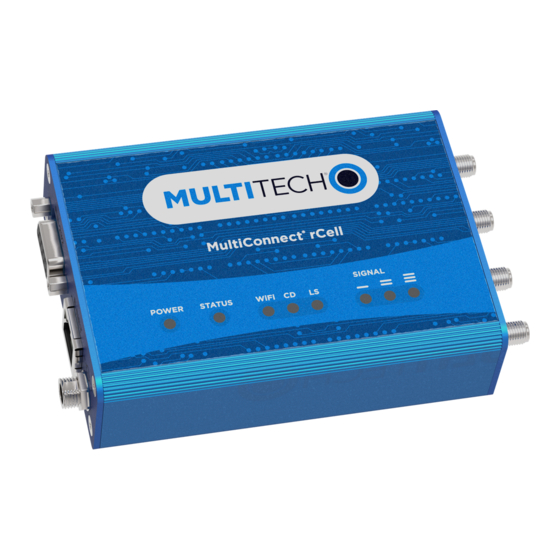
CHAPTER 1 PRODUCT OVERVIEW Descriptions of LEDs The top panel contains the following LEDs: ■ Power and Status LEDs—The Power LED indicates that DC power is present and the Status LED blinks when the unit is functioning normally. ■ Wi-Fi—Indicates if the device is serving as a Wi-Fi access point or acting as a Wi-Fi client. Not all models support Wi-Fi. -
Page 11: Side Panel Connectors
CHAPTER 1 PRODUCT OVERVIEW Side Panel Connectors The device has connectors on both sides of the housing. The right side of the device contains a SIM card holder, a reset button, a GPS antenna connector, and a cellular-auxiliary antenna connector pair. Depending on the model of your device, the GPS and WiFi antenna connector may or may not appear. -
Page 12: Ethernet Led Descriptions
CHAPTER 1 PRODUCT OVERVIEW Label Description Power 9-32 VDC power receptacle for provided power cord. The device uses a Globtek GT-41052- 1509 9V 1.7A power supply. Ethernet LED Descriptions Two Ethernet LEDs are physically on the RJ-45 connector(s). The table that follows describes these LEDs. Ethernet Link Right LED on Ethernet connector. - Page 13 CHAPTER 1 PRODUCT OVERVIEW Category Description Weight 8.2 ounces or 230 grams Environment Operating Temperature -40° C to +85° C Humidity Relative humidity 15% to 93% non-condensing Certifications, Compliance, Warranty EMC Compliance EN55022 Class B EN55024 Safety Compliance UL 60950-1 UL 201 IEC 60950-1 ANSI/ISA 12.12.01 2013 and CSA C22.2 No.
-
Page 14: Dimensions
CHAPTER 1 PRODUCT OVERVIEW Dimensions Label locations The images that follow show where you can find regulatory information for your device. ® MultiConnect rCell 100 MTR-H5 User Guide... - Page 15 CHAPTER 1 PRODUCT OVERVIEW ® MultiConnect rCell 100 MTR-H5 User Guide...
- Page 16 CHAPTER 1 PRODUCT OVERVIEW ® MultiConnect rCell 100 MTR-H5 User Guide...
-
Page 17: Power Draw
CHAPTER 1 PRODUCT OVERVIEW Power Draw Radio Protocol Cellular Cell Box (AVG) Measured TX Pulse (AVG) Total Inrush Charge Connection No Data Current (Amps) at Amplitude Current Measured in (Amps) Max Power (Amps) for GSM850 or Millicoulomb (mC) Peak Current for HSDPA) 7.0 Volts GSM 850 MHz... -
Page 18: Bluetooth Specifications
CHAPTER 1 PRODUCT OVERVIEW Mode Frequency TX (MHz) Frequency RX (MHz) Channels TX - RX Offset WCDMA850 824 to 849 869 to 894 TX: 4132 to 4233 45 MHz (Band V) Additional: 782, 787, 807, 812, 837, 862 RX: 4357 to 4458 Additional: 1007, 1012, 1032, 1037, 1062, 1087 WCDMA900... -
Page 19: Wlan Specifications (Wi-Fi)
CHAPTER 1 PRODUCT OVERVIEW WLAN Specifications (Wi-Fi) Standard Mode Frequency Range Data Rate Typical Output Typical WLAN (MHz) (Mbps) Power (sBm) IEEE 802.11b DSSS / CCK 2400 to 2483.5 1, 2, 5.5, 11 +20.0 dBm at -88.0dBm at 8% 11Mbps, CCK PER, 11Mbps IEEE 802.11g OFDM... -
Page 20: Chapter 2 Safety Warnings
■ When this battery starts to weaken, the date and time may be incorrect. ■ Battery is not user replaceable. If the battery fails, the device must be sent back to MultiTech Systems for battery replacement. ■ Lithium cells and batteries are subject to the Provisions for International Transportation. Multi-Tech Systems, Inc. -
Page 21: Atex (Europe Only)
CHAPTER 2 SAFETY WARNINGS AVERTISSEMENT – Risque d'explosion – Le remplacement des composants peut annuler la compatibilité du produit avec les zones de Classe I Division 2. AVERTISSEMENT – Risque d'explosion – Ne débranchez pas l'équipement sauf s'il est hors tension ou si la zone est considérée comme non dangereuse. -
Page 22: Interference With Pacemakers And Other Medical Devices
CHAPTER 2 SAFETY WARNINGS ■ Operating your device close to other electronic equipment may cause interference if the equipment is inadequately protected. Observe any warning signs and manufacturers’ recommendations. ■ Different industries and businesses restrict the use of cellular devices. Respect restrictions on the use of radio equipment in fuel depots, chemical plants, or where blasting operations are in process. - Page 23 CHAPTER 2 SAFETY WARNINGS Compliance of the device with the FCC and IC rules regarding RF Exposure was established and is given with the maximum antenna gain as specified above for a minimum distance of 20 cm between the devices radiating structures (the antenna) and the body of users.
-
Page 24: Chapter 3 Cellular Information
The cellular radio portion of the device is approved with the following antenna or for alternate antennas meeting the given specifications. Manufacturer: Laird Technologies. Description: HEPTA-SM Model Number: MAF94300 Multi-Tech Part Number: 45009735L MultiTech Ordering Information: Model Quantity ANHB-1HRA ANHB-10HRA ANHB-50HRA 3G Antenna Requirements/Specifications Category Description Frequency Range 824 –... -
Page 25: Gps Antenna Specifications
CHAPTER 3 CELLULAR INFORMATION GPS Antenna Specifications Manufacturer: Trimble Description: GPS Antenna with low noise amplifier Model Number: 66800-52 Multi-Tech Part Number: 45009665L MultiTech Ordering Information Model Quantity ANGPS-1MM ANGPS-10MM ANGPS-50MM Antenna Specifications Category Description Frequency Range 1575.24 MHz Impedance... -
Page 26: Antenna Specifications
CHAPTER 3 CELLULAR INFORMATION Antenna Specifications Category Description Frequency Range 2.4000 to 2.4835 GHz Impedance 50 Ohms VSWR VSWR should not exceed 2.0:1 at any point across the bands of operation Peak Radiated Gain 2.3 dBi on azimuth plane Radiation Omni-directional Polarization Linear Vertical... -
Page 27: Chapter 4 Installing The Router
CHAPTER 4 INSTALLING THE ROUTER Chapter 4 Installing the Router Installing the Router To use the router’s cellular features, connect a suitable antenna to the antenna connector. If your device is capable of supporting antenna diversity, see the section about diversity. Some routers support Wi-Fi. -
Page 28: Mounting The Device
CHAPTER 4 INSTALLING THE ROUTER Mounting the Device Locate the groove on the bottom of the modem. Slide the mounting rod through the groove. To secure the rod to the desired surface, place and tighten two screws in the holes on either end of the mounting rod. -
Page 29: Restoring User Defined Settings To The Device
CHAPTER 4 INSTALLING THE ROUTER Use the pin to quickly press and release the RESET button. The device reboots. Here are the different options using the RESET button: ■ To reboot, press RESET for less than 3 seconds. ■ To set factory settings or user-defined defaults (if previously set), press RESET for 3 to 29 seconds. ■... -
Page 30: Chapter 5 Using The Wizard To Configure Your Device
CHAPTER 5 USING THE WIZARD TO CONFIGURE YOUR DEVICE Chapter 5 Using the Wizard to Configure Your Device First-Time Setup If you need to change the mode of your device, this is the only way to do so. This section is not available through the device management software. - Page 31 CHAPTER 5 USING THE WIZARD TO CONFIGURE YOUR DEVICE In the Protocol Support field, choose the internet protocol from the drop down menu (select from IPv4 and IPv6). In the Protocol Support field, choose IPv4 only as the cell radios for C2 and EV3 do not support IPv6. In the IPv4/IPv6 Address field, type the router's IP address.
- Page 32 CHAPTER 5 USING THE WIZARD TO CONFIGURE YOUR DEVICE From Baud Rate, select baud rate in BPS for the serial port from the drop down list. Default setting is 115200. In the Flow Control field, select the flow control option from the drop down list provided. Choose from NONE or RTS-CTS.
-
Page 33: Chapter 6 Configuring Your Device
Click Home to display the following information: ■ Router: ■ Model Number: The MultiConnect rCell model ID. ■ Serial Number: The MultiTech device ID. ■ IMEI: International Mobile Station Equipment Identity. Note: Not applicable for the MTR-C2 or MTR-EV3 models. ■... -
Page 34: Unavailable Services In Ppp-Ip Passthrough And Serial Modem Modes
CHAPTER 6 CONFIGURING YOUR DEVICE ■ IP Address: Current cellular WAN IP address issued to this device by the cellular carrier. ■ Roaming: Indicates whether or not this device's cellular link is currently connected to its home network. ■ Phone number: Device's cellular phone number also known as Mobile Directory Number (MDN). This field is blank if the MDN is not stored in the SIM card. -
Page 35: Wan Setup
CHAPTER 6 CONFIGURING YOUR DEVICE Note: When a DNS request is received, the router forwards the request to a remote DNS server if there is no record in the router’s cache. New requests are cached in the router for future requests. -
Page 36: Failover Configuration Fields
CHAPTER 6 CONFIGURING YOUR DEVICE If you are finished making changes, click Save and Restart. Failover Configuration Fields Field Description Monitoring Mode Use the drop-down list to select the mode to connect to the host: PASSIVE or ACTIVE. Interval Enter the number of seconds between each check. Default is 60 seconds. Host Name Enter the host name or IP address to use for the check. -
Page 37: Entering Authentication Information
CHAPTER 6 CONFIGURING YOUR DEVICE Entering authentication information Your DDNS server requires you to identify yourself before you can make changes. In the Username field, type the name that can access the DDNS Server. The default is NULL. You receive your name when you register with the DDNS service. -
Page 38: Gps Server Configuration
CHAPTER 6 CONFIGURING YOUR DEVICE There are four areas of GPS configuration including: Server Configuration, Local Configuration, Client Configuration and NMEA Configuration along with Current Position information. Notes: ■ All enabled sentences are forwarded periodically using the interval specified in the NMEA Configuration section. -
Page 39: Configuring Nmea Sentences
CHAPTER 6 CONFIGURING YOUR DEVICE Configuring NMEA Sentences To configure the time interval, additional prefix or ID information, and which NMEA sentences that can be sent: Go to Setup > GPS Configuration > NMEA Configuration and in the Interval field, type the amount of time, in seconds, that passes before the NMEA information is sent. -
Page 40: Configuring Device To Act As Server
CHAPTER 6 CONFIGURING YOUR DEVICE In the Server IP Address field, enter the address of the far-end TCP, UDP, or SSL/TLS server. In the Server Port field, enter the port value used by the far-end TCP, UDP, or SSL/TLS server. If the primary server is unavailable, in the Secondary IP Address field, enter the address of the alternate TCP, UDP, or SSL/TLS server. -
Page 41: Time Configuration
CHAPTER 6 CONFIGURING YOUR DEVICE To save your changes, click Save and Restart. Time Configuration You can configure how your router manages the setting of time on its domain of systems. The system date and time display in these formats: MM/DD/YYYY / HH:MM. You can set the date and time manually, or you can configure the router to get this information from an SNTP server. -
Page 42: Editing Or Deleting An Existing Network
CHAPTER 6 CONFIGURING YOUR DEVICE Click Finish. To save your changes, click Save and Restart. Editing or Deleting an Existing Network To delete a network, click red X. At the top of the pane, a message tells you the network is deleted. To undo the delete, click the Undo link found in the message. -
Page 43: Chapter 7 Setting Up Wireless Features
CHAPTER 7 SETTING UP WIRELESS FEATURES Chapter 7 Setting Up Wireless Features Setting Up Wi-Fi Access Point If you ordered a device with Wi-Fi capability, your router can be configured as a wireless access point (AP). This allows Wi-Fi enabled devices to connect to the router using Wi-Fi. The Wi-Fi access point can have up to 8 clients at a time. -
Page 44: Viewing Information About Wi-Fi Clients Using Your Wireless Network
CHAPTER 7 SETTING UP WIRELESS FEATURES To select WEP mode: From the Encryption drop-down list, select the encryption to be used. Choose from 64 bit 10 hex digits or 128 bit 26 hex digits. To generate a key from a phrase, in the Passphrase field, type a phrase. Click Generate. To manually enter keys, type the keys in the Key 1, Key 2, Key 3 or Key 4 fields. -
Page 45: Setting Up Bluetooth
CHAPTER 7 SETTING UP WIRELESS FEATURES If desired, add additional access points to the list of Saved Networks. The router tries to connect to Saved Networks in the order they are listed. You can change the order by clicking the up or down arrows shown under Options. - Page 46 CHAPTER 7 SETTING UP WIRELESS FEATURES ■ CR: Three carriage returns must be received from the Bluetooth side before TCP/UDP connection is established to the remote server. From the Connection Termination drop-down list select a disconnect method for the IP pipe. Options are: ■...
-
Page 47: Chapter 8 Setting Up The Firewall
CHAPTER 8 SETTING UP THE FIREWALL Chapter 8 Setting Up the Firewall Defining firewall rules The router's firewall enforces a set of rules that determine how incoming and outgoing packets are handled. By default, all outbound traffic originating from the LAN is allowed to pass through the firewall, and all inbound traffic originating from external networks is dropped. -
Page 48: Mac Filtering
CHAPTER 8 SETTING UP THE FIREWALL In the Destination Port field, type the port for which that the packets are destined. Common destination ports are listed in the Destination Port field's attached drop down list. Type ANY if the destination port does not matter. - Page 49 CHAPTER 8 SETTING UP THE FIREWALL In the Name field of the Add Route dialog box, type the name of the route. In the Address field, type the remote network IP address of the remote location. In the Mask field, type the network mask that is assigned on the remote location. In the Gateway field, type the IP address of the routing device that supports the remote IP Network.
-
Page 50: Chapter 9 Setting Up Cellular Features
CHAPTER 9 SETTING UP CELLULAR FEATURES Chapter 9 Setting Up Cellular Features Configuring Cellular To configure how cellular is used on your router: On the Web Management interface, go to Cellular > Cellular Configuration to display the Cellular Configuration window. If you choose IPv6 Passthrough mode, you must select Administration > Initial Setup. - Page 51 CHAPTER 9 SETTING UP CELLULAR FEATURES Field Description Dial Prefix The modem AT command that initiates a PPP connection, usually ATDT or ATD. SIM Pin The pin used to unlock the SIM for use (only required if the SIM is locked). This does not apply to CDMA radios.
-
Page 52: Unavailable Services In Ppp-Ip Passthrough And Serial Modem Modes
CHAPTER 9 SETTING UP CELLULAR FEATURES *Note: If you choose PPP-IP Passthrough and Serial Modem mode, this field is not available. Unavailable Services in PPP-IP Passthrough and Serial Modem Modes In both PPP-IP Passthrough and Serial Modem modes, many rCell services described in this document are non- configurable and therefore do not appear in the device configuration menu. -
Page 53: Wake Up On Call General Configurations
CHAPTER 9 SETTING UP CELLULAR FEATURES Wake Up On Call General Configurations Field Description Wake Up on Call check box Enables the Wake Up On Call feature. Dial On Demand LAN When checked, the router allows network activity on the LAN that needs WAN access to trigger the Wake Up and establish the cellular link. -
Page 54: Radio Status
CHAPTER 9 SETTING UP CELLULAR FEATURES Radio Status Field Description Module Information IMEI International Mobile Station Equipment Identifier IMSI International Mobile Subscriber Identifier Manufacturer Company that developed the cellular module Model Cellular module model number Hardware Revision Module's hardware revision MDN (Phone Number) Mobile Directory Number. -
Page 55: Chapter 10 Configuring Sms
CHAPTER 10 CONFIGURING SMS Chapter 10 Configuring SMS Configuring SMS This function is not available if you enable SMS through Cellular > Wake Up On Call. To enable short message service (SMS) via the Web Management interface or API: From the Web Management interface, go to SMS > SMS Configuration > General. Check Enabled. -
Page 56: Sending An Sms Message
CHAPTER 10 CONFIGURING SMS ■ Enter the phone number and click Add Number. ■ Note: Due to differences between service providers, for every US number you add to the Whitelist, create two separate entries: 1) one using the phone number and 2) the other using 1 + phone number. -
Page 57: Viewing Sent Sms Messages
CHAPTER 10 CONFIGURING SMS Go to SMS > Received to display the Received SMS window. The messages are sorted by date with the most recent messages on top. The table shows up to 30 characters for each message. To view the full message, click the eye icon to the right of the message entry. To delete an SMS message, click the X under Options to the right of the message. -
Page 58: Chapter 11 Defining Tunnels
CHAPTER 11 DEFINING TUNNELS Chapter 11 Defining Tunnels Setting Up GRE Tunnels Tunneling allows the use of a public network to convey data on behalf of two remote private networks. It is also a way to transform data frames to allow them to pass networks with incompatible address spaces or even incompatible protocols. -
Page 59: Ipsec Tunnel Configuration Field Descriptions
CHAPTER 11 DEFINING TUNNELS The default set of DH Group Algorithms is: DH2(1024-bit), DH5(1536-bit), DH14(2048-bit), DH15(3072-bit), DH16(4096-bit), DH17(6144-bit), DH18(8192-bit), DH22(1024-bit), DH23(2048-bit), and DH24(2048-bit). To set up a Network-to-Network VPN tunnel on your router: From the Web Management interface, go to Tunnels > IPsec Tunnels. Click Add Tunnel in upper right. - Page 60 CHAPTER 11 DEFINING TUNNELS Field Description Remote Network Mask This field is used in conjunction with the Remote Network Route field, to describe the remote endpoint's subnet. It identifies packets that are routed over the tunnel to the remote network. Tunnel Type Internet Key Exchange (IKE) for host-to-host, host-to-subnet, or subnet- to-subnet tunnels.
-
Page 61: Unavailable Services In Ppp-Ip Passthrough And Serial Modem Modes
CHAPTER 11 DEFINING TUNNELS Unavailable Services in PPP-IP Passthrough and Serial Modem Modes In both PPP-IP Passthrough and Serial Modem modes, many rCell services described in this document are non- configurable and therefore do not appear in the device configuration menu. If you choose one of these modes, all sections between this and the previous note on this subject are not available. -
Page 62: Chapter 12 Device Administration
CHAPTER 12 DEVICE ADMINISTRATION Chapter 12 Device Administration Configuring Device Access This section contains configurations that determine how the device can be accessed as well as security features that decrease susceptibility to malicious activity. To display the Access Configuration window containing the fields described below, go to Administration > Access Configuration. -
Page 63: Icmp
CHAPTER 12 DEVICE ADMINISTRATION Field Description Enabled Enables SSH redirect which automatically redirects users trying to access the device via SSH. Port The port the router listens for SSH requests on. Via LAN If checked, the router listens and responds to SSH requests from the LAN. -
Page 64: Configuring Ip Defense
CHAPTER 12 DEVICE ADMINISTRATION Field Description Enabled Enables the Ping Limit feature. Per Second Allowed number of pings per second before burst points are consumed. Once burst points run out, ICMP packets will be dropped. Burst Number of burst points. On a period where the Per Second limit is not reached, one burst point is regained, up to this maximum. -
Page 65: Brute Force
CHAPTER 12 DEVICE ADMINISTRATION In the Per Second field, type the average number of ICMP pings to the router, and the allowed number of pings per second before burst points are consumed. Once burst points run out, ICMP packets will be dropped. -
Page 66: Uploading A New Certificate
CHAPTER 12 DEVICE ADMINISTRATION In the Email Address field, enter the email address of the person responsible for the router. Typically this is the administrator. This field may be left blank. Click Generate. Wait until the certificate is generated. You may have to reboot to complete the operation. -
Page 67: Unavailable Services In Ppp-Ip Passthrough And Serial Modem Modes
CHAPTER 12 DEVICE ADMINISTRATION To define how often the device connects to DeviceHQ to send GPS data, set the GPS Data Interval field to the desired number of minutes, between 1-10080 (1 minute to 1 week). Note: Some MTR models do not have GPS. -
Page 68: Customizing The User Interface
CHAPTER 12 DEVICE ADMINISTRATION Select the Start Date from the calendar picker. Enter the Limit in MB for data usage. In Notify At, enter the percentage of the limit that triggers notification to be sent. Select alert recipients from Recipient Group. Select how you want to send alerts by clicking Email, SMS, or both. -
Page 69: Specifying Device Settings
CHAPTER 12 DEVICE ADMINISTRATION ■ ■ Address 1 ■ Address 2 ■ City ■ State/ Prv ■ Zip Code ■ City To add a phone number: Click Add Phone. A label can appear next to the phone number, for example Fax or Phone or International. In the Label field, enter text that describes the phone number. -
Page 70: Upgrading Firmware
Before you upgrade your firmware, save your present configuration as a backup. See DeviceHQ Go to the MultiTech website, locate the firmware upgrade file you want for your router, and download this file to a known location. -
Page 71: Using The Router's Debugging Options
CHAPTER 12 DEVICE ADMINISTRATION Click Restore. The device reboots. To save your current configuration to a file, go to Save Configuration To File: Click Save. Navigate to the location where you wish to save the file and select location. This option is only available if you had reset to user-defined configuration. (Also, holding the reset button on the device for 30 seconds overrides user-defined settings and resets to factory default.) To reset the router's configuration to the factory settings, go to Reset to Factory Default Configuration: Click Reset. -
Page 72: Automatically Rebooting The Device
CHAPTER 12 DEVICE ADMINISTRATION Automatically rebooting the device To specify the amount of time that passes before the device automatically reboots itself: Go Administration > Debug Options > Auto Reboot Timer, select DISABLED, HOUR OF DAY, and TIMER from the drop-down list under Auto Reboot. In the Auto Reboot Timer field, select the Hour of the Day (0-23) and then enter Hour of the Day to Restart (0-23). -
Page 73: Ping And Reset Options
CHAPTER 12 DEVICE ADMINISTRATION To save your settings, click Save and Restart. Ping and Reset Options Perform a Ping Test Ping allows you to test the IP address or URL to ensure it is operational. To perform a ping test: Go to Administration >... -
Page 74: Chapter 13 Device Status
CHAPTER 13 DEVICE STATUS Chapter 13 Device Status Viewing Device Statistics The router collects sent/received traffic data for WAN, Cellular, and Ethernet networks. The daily statistical data is stored on the device for a 365-day period. All data that is older than 365 days is automatically deleted. From Status &... -
Page 75: Mail Log
CHAPTER 13 DEVICE STATUS The associated run-time logs for this section. Mail Log Mail Log shows the recent email delivery attempts and the mail log details. Mail log entries are sorted by date with the most recent on top. (This function is not available if you use PPP-IP Passthrough or Serial Modem mode). You can select the number of emails to display in the queue. -
Page 76: Service Statistics
CHAPTER 13 DEVICE STATUS Service Statistics On the Web Management interface side menu, click Status & Logs > Services to display the Service Statistics window. (If you use PPP-IP Passthrough mode, go to Status menu and follow the remaining instructions.) This window shows the configuration (enabled or disabled) and the status of the following services: ■... -
Page 77: Appendix: Regulatory Information
APPENDIX: REGULATORY INFORMATION Appendix: Regulatory Information 47 CFR Part 15 Regulation Class B Devices This equipment has been tested and found to comply with the limits for a Class B digital device, pursuant to part 15 of the FCC Rules. These limits are designed to provide reasonable protection against harmful interference in a residential installation. -
Page 78: Fcc And Ic Antenna Requirements Toward License Exempt Radio Transmitters (Bluetooth/Wlan)
APPENDIX: REGULATORY INFORMATION FCC and IC Antenna Requirements Toward License Exempt Radio Transmitters (Bluetooth/WLAN) The license-exempt Bluetooth/WLAN radio transmitter contained in this equipment may only be operated with an antenna of a type, a maximum gain and the required antenna impedance as approved and specified below. To reduce potential radio interference to other users, choose the antenna type and it's gain so that the equivalent isotropically radiated power (EIRP) is not more than that necessary for successful communication. -
Page 79: Restriction Of The Use Of Hazardous Substances (Rohs)
2011/65/EU of the European Parliament (Restriction of the use of certain Hazardous Substances in electrical and electronic equipment - RoHS). These MultiTech products do not contain the following banned chemicals ■ Lead, [Pb] < 1000 PPM ■... -
Page 80: Reach Statement
Substances) complements the WEEE Directive by banning the presence of specific hazardous substances in the products at the design phase. The WEEE Directive covers all MultiTech products imported into the EU as of August 13, 2005. EU-based manufacturers, distributors, retailers and importers are obliged to finance the costs of recovery from municipal collection points, reuse, and recycling of specified percentages per the WEEE requirements. -
Page 81: Information On Hs/Ts Substances According To Chinese Standards
APPENDIX: REGULATORY INFORMATION Information on HS/TS Substances According to Chinese Standards In accordance with China's Administrative Measures on the Control of Pollution Caused by Electronic Information Products (EIP) # 39, also known as China RoHS, the following information is provided regarding the names and concentration levels of Toxic Substances (TS) or Hazardous Substances (HS) which may be contained in Multi-Tech Systems Inc. -
Page 82: Information On Hs/Ts Substances According To Chinese Standards (In Chinese)
APPENDIX: REGULATORY INFORMATION Information on HS/TS Substances According to Chinese Standards (in Chinese) 依 依 照 照 中 中 国 国 标 标 准 准 的 的 有 有 毒 毒 有 有 害 害 物 物 质 质 信 信 息 息 根据中华人民共和国信息产业部...
Need help?
Do you have a question about the MultiConnect rCell 100 and is the answer not in the manual?
Questions and answers