Table of Contents
Advertisement
Quick Links
Advertisement
Table of Contents

Related Manuals for Multitech MultiConnect rCell 500 R2


Summary of Contents for Multitech MultiConnect rCell 500 R2
- Page 1 ® MultiConnect rCell 500 R2 Series Router User Guide...
- Page 2 Legal Notices The MultiTech products are not designed, manufactured or intended for use, and should not be used, or sold or re-sold for use, in connection with applications requiring fail-safe performance or in applications where the failure of the products would reasonably be expected to result in personal injury or death, significant property damage, or serious physical or environmental damage.
-
Page 3: Table Of Contents
CONTENTS Contents Chapter 1 – Product Overview ..........................7 Product Overview................................7 Package Contents................................7 System Requirements ..............................7 LED Indicators ................................8 Specifications ................................9 RF Specifications ................................. 10 Using DeviceHQ for Device Management........................10 Chapter 2 – Installing and Using the Router ......................11 Installing SIM Cards.............................. - Page 4 CONTENTS Port-Based VLAN ............................... 24 Tag-Based VLAN ................................ 24 Port Speed................................. 24 Port Setup ................................. 24 Wi-Fi Setup.................................. 25 2.4GHz and 5GHz AP Router Mode .......................... 25 Wireless Client List..............................26 Advanced Configuration............................26 IPv6 Setup ................................... 26 Static IPv6.................................. 27 DHCPv6..................................
- Page 5 CONTENTS Chapter 4 – Advanced Network ..........................39 Advanced Network..............................39 Firewall..................................39 Packet Filters................................39 URL Blocking (HTTP only) ............................39 MAC Control................................40 IPS (Intrusion Prevention Systems)........................... 40 Options..................................40 Quality of Service ............................... 40 QoS Configuration..............................41 Rule-based QoS .................................
- Page 6 CONTENTS Import Trusted Client Certificate ..........................61 Import Trusted Client Key ............................61 Issue Certificates ............................... 62 Import and Issue Certificate............................62 Chapter 5 – Applications ............................63 Applications................................. 63 Mobile Application..............................63 Remote Management ............................... 64 Captive Portal................................64 Digital IO..................................
-
Page 7: Chapter 1 - Product Overview
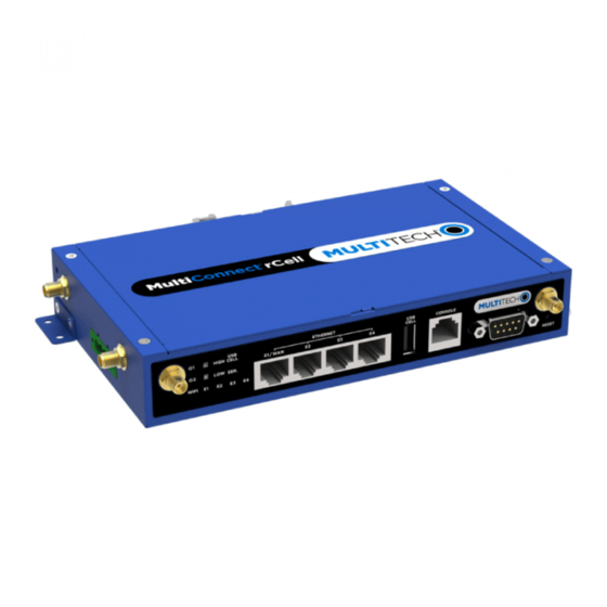
Chapter 1 – Product Overview Product Overview This guide describes the MultiConnect rCell 500 R2 Series Router. The MultiConnect rCell R2 500 offers secure data communication between different types of devices. It features redundant power supplies and dual SIM capability... -
Page 8: Led Indicators
PRODUCT OVERVIEW LED Indicators Indicator Label Description Power Source 1 Continuously ON: Device is powered by source 1. Power Source 2 Continuously ON: Device is powered by source 2. Note: If both power source 1 and 2 are connected, the device chooses power source 1 first. -
Page 9: Specifications
PRODUCT OVERVIEW Specifications MTR5-LEU2 Category Description General Performance LTE, WCDMA, GSM/GPRS/EDGE Frequency Bands MTR5-LEU2-B04.R2 4G-LTE/FDD: B1, B3, B7, B8, B20, B28A, TDD: B38, B40, B41 3G-WCDMA: B1, B8 2G-GSM/GPRS/EDGE Band: 900/1800 MHz MTR5-L12G2-B04.R2 4G-LTE/TDD: B42, B43, B48 (CBRS) Radio Cellular MTR5-LEU2-B04.R2 - 4G LTE Radio with 3G/2G fallback MTR5-L12G2-B04.R2 –... -
Page 10: Rf Specifications
DeviceHQ is a cloud-based device management tool for remote monitoring, upgrades, and configuring devices. For information on creating and using a DeviceHQ account, go to the http://www.multitech.net/developer/software/devicehq/. Note: If you are not using DeviceHQ as the management system, disable DeviceHQ as the management system within the software. -
Page 11: Chapter 2 - Installing And Using The Router
INSTALLING AND USING THE ROUTER Chapter 2 – Installing and Using the Router Installing SIM Cards The SIM card slots are located on the bottom of the device. Note: Before installing or changing the SIM card, make sure the device is turned OFF and power is disconnected. -
Page 12: Attaching Cables And Antennas
INSTALLING AND USING THE ROUTER Attaching Cables and Antennas Attach 4G antennas. For the MTR5-LEU2-B04.R2: Attach 4G antennas to the device's front panel by screwing them into the designated connectors. For the MTR5-L12G2-B04.R2: Attach 4G antennas to the device's right-side panel by screwing them into the designated connectors. -
Page 13: Using Setup Wizard
INSTALLING AND USING THE ROUTER Using Setup Wizard If you are using a 3G/4G network, verify SIM card has been installed before starting setup. Configure this device using the web UI. To access the web UI, enter the IP Address into your browser. The default IP Address is 192.168.2.1. -
Page 14: Status
INSTALLING AND USING THE ROUTER If you choose PPTP Server, selection options for authentication and MPPE. Create username and password for one PPTP client. To create additional usernames and passwords, select Advanced Network > VPN > PPTP to add more. Click Next. If you choose L2TP, select from Client for the device to connect to another L2TP server or Server for other L2TP clients to connect to the device. -
Page 15: Lan Client List
INSTALLING AND USING THE ROUTER LAN Client List LAN Client List: This shows a list of all the current Ethernet and Wi-Fi client devices that are detected and active on the LAN and Wi-Fi interfaces. Firewall Status Packet Filters: This shows all the detected contents that match with configured packet filter rules that have logging alert enabled. -
Page 16: Chapter 3 - Basic Network
BASIC NETWORK Chapter 3 – Basic Network Basic Network WAN Setup This device has three WAN interfaces to support different WAN connections. Configure these individually to maximize Internet connection setup. Ethernet WAN: Configure the E1 or E2 Ethernet port as a WAN. To setup, plug in the Ethernet cable from an external modem and follow UI setup. -
Page 17: Internet Setup
BASIC NETWORK WAN interface failover and fallback. If an interface serves as a seamless failover WAN, the WAN connection will be activated after the system has operated normally, even without data flow in it. When the primary connection is broken, fast switching data flow to the WAN interface is the major concern for seamless failover.) Note: Your ISP will charge the connection fee even if Operation mode is set to seamless... - Page 18 BASIC NETWORK B, the specified SIM card is the only one used for negotiation parameters between the device and mobile base station. Find SIM Configuration for all options beneath the 3G/4G WAN Type configuration window. Dial-up Profile: Use information given by your 3G/4G data service provider to setup connection including APN, dialed number and account or password.
-
Page 19: Internet Setup For Ethernet Wan
BASIC NETWORK Physical Interface: Indicate which 3G/LTE modem is used for network scan. SIM Status indicates which SIM card is used for Network Scan. Network Type: Set network scan type. You can choose 2G only or prefer, 3G only or prefer, LTE only or prefer, or Auto. -
Page 20: Ppp Over Ethernet (Pppoe)
BASIC NETWORK Connection Control: Select the connection control scheme from the list. Options are: Auto-Reconnect (Always on), Connect-on-Demand, and Connect Manually. MTU: The default value is 0 (Auto). NAT: Check to enable. If you enable, there will be no NAT mechanism between the LAN and WAN. Network Monitoring (keep alive): Monitor WAN interface connection status. -
Page 21: Pptp Client
BASIC NETWORK WAN IP Alias: Some ISPs will provide a fixed IP address for management purposes. If so, enter this address. PPTP Client Select Point-to-Point Tunneling Protocol (PPTP) when your ISP uses this type of connection. The ISP will provide you with a username and password. -
Page 22: Internet Setup For Wi-Fi Wisp Wan
BASIC NETWORK NAT: Check to enable. If you enable, there is no NAT mechanism between the LAN and WAN. Network Monitoring (keep alive): Monitor WAN interface connection status. As a result, the system can prevent the WAN connection from auto-timeout and disconnects after a period of inactivity. Check Enable. -
Page 23: Load Balance
BASIC NETWORK Priority: Each APN will need to assign a priority, 1 is top priority. Profile: Enable or Disable this APN profile. Load Balance This device supports a multi-WAN, load balancing function when multiple WAN interfaces are set as active. Load balance manages the outbound traffic to maximize available bandwidth on multiple WAN links. -
Page 24: Vlan
BASIC NETWORK To use this function, check Enable. Enter the IP address for two LAN devices. Enter the Time interval. Click Save. VLAN The VLAN function allows you to divide a local network into virtual LANs. In some cases, the network needs multiple LANs with support certain services. -
Page 25: Wi-Fi Setup
BASIC NETWORK Wi-Fi Setup The Wi-Fi settings allow you to set the wireless LAN configuration. Once the configurations is complete, your device will be ready to support your local Wi-Fi devices. This device supports the following wireless operation modes: AP Router Mode, WDS Hybrid Mode, and WDS Only Mode. -
Page 26: Wireless Client List
BASIC NETWORK Authentication Type Description WPA2 (802.11x) In this mode, specify the IP address and port number for the RADIUS server. The key value is shared by the device and RADIUS server. The available encryption modes are TKIP, AES , or TKIP/AES. WPA-PSK/WPA2-PSK This mode is used when some clients only support WPA-PSK and others use WPA2- PSK. -
Page 27: Static Ipv6
BASIC NETWORK Static IPv6 When setting up Static IPv6, do the following and then click Save: WAN IPv6 address settings: IPv6 address: Enter the IPv6 address. IPv6 addresses are 128 bits, the address space is larger than IPv4. Note: An example of an IPv6 address is "2001:0db8:85a3:0000:000:8a2e:0370:7334" Subnet Prefix Length: Enter the Subnet Mask prefix length. -
Page 28: Nat Setup
BASIC NETWORK Auto-configuration type: Select Stateless or Stateful (Dynamic IPv6). Router Advertisement Lifetime: Each router periodically multicasts a Router Advertisement from each of its interfaces, announcing the IP address(es) of that interface. Use this option to set the period that the router broadcasts its router advertisements. NAT Setup NAT Loopback Allows you to access the WAN IP address from inside your home or office network. -
Page 29: Dmz
BASIC NETWORK Enable: Check this item to enable this feature. DMZ (Demilitarized Zone) Host is a host without the protection of a firewall. It allows a computer to be exposed to unrestricted 2-way communication for Internet games, Video conferencing, Internet telephony, and other special applications. -
Page 30: Routing Information
BASIC NETWORK Routing Information A routing table, or routing information base (RIB), is a data table stored in a router or networked computer that lists the routes to other network destinations. The routing table contains information about the topology of the network immediately around it. -
Page 31: Serial Port
BASIC NETWORK Gateway: Optional. This would be the alternate Gateway IP address. Assign another gateway to your local computer when the DHCP server offers an IP address. For example, this gateway assigns an IP address to a local computer but the computer accesses the Internet through another gateway. Server: Enable if you want the DHCP server active or Disable. -
Page 32: Serial Port 2 - Three-Wires Terminal Block Rs232 / Rs485 Pinout
BASIC NETWORK Serial Port 2 - Three-wires terminal block RS232 / RS485 pinout Serial Port 1 Configuration (DB-9) The DB9 serial port is a 9 pins RS232 DTE interface. The port can be set up as Paknet or virtual Com with TCP client, TCP server, UDP or RFC-2217 to access the external RS232 serial device on the DB9 serial port. -
Page 33: Tcp Server Mode
BASIC NETWORK Operation Mode: Choose TCP Client. Connection Control: To keep the connection with the remote TCP server all the time, choose Always On. To keep the connection only when transmitting data, choose ON-Demand. Connection Idle Timeout: The TCP connection will be terminated if it idles longer than this timeout setting. -
Page 34: Udp Mode
BASIC NETWORK Delimiter Character 2: process and send data over IP when the last TWO characters in the serial data stream matches. Check enable and enter Hex value for the character to activate this function. Data Timeout Transmit: process and send data over IP based on configured time value, when the serial port has received the data for configured time, it processes and sends the data. -
Page 35: Serial Port 2 Configuration (Terminal Block)
BASIC NETWORK Secondary Remote IP: Defines secondary remote server IP address that the device connects to when it is originating call. Secondary Remote Port: Defines secondary remote server IP port that the device connects to when it is originating call. DTR Turn Off Time: Defines how long to turn off DTR signal during TCP disconnect. -
Page 36: Tcp Server Mode
BASIC NETWORK Alive Check Timeout: The TCP connection will be terminated if it doesn't receive a response from the alive check. Data Packing: Data Buffer Length: process and send data over IP after serial data buffer length is received. 0 sends data immediately without waiting. -
Page 37: Udp Mode
BASIC NETWORK Legal IP / FQDN Host: Click Edit to enter the remote host IP address of FQDN (Fully Qualified Domain Name). The remote host is the TCP server. To Host: Enter the remote host IP address. Remote Port: Enter the remote host TCP port. Enable: Check to enable the rule. - Page 38 BASIC NETWORK Modbus Priority: Defines the priorities from specific IPs, Modbus IDs, or Function Codes ® MultiConnect rCell 500 R2 Series Router User Guide...
-
Page 39: Chapter 4 - Advanced Network
ADVANCED NETWORK Chapter 4 – Advanced Network Advanced Network This device supports advanced network features, such as Firewall, QoS, Security, Redundancy, and Management. Firewall The firewall function includes Packet Filters, URL Blocking, MAC control, and Options. Packet Filters Packet filters include outbound and inbound filters. This enables you to control what packets are allowed to pass through the router. -
Page 40: Mac Control
ADVANCED NETWORK MAC Control Mac Control allows you to assign different access rights for different users based on a device's MAC address. MAC Control: Enable or Disable MAC Control. Black List/White List: Select Allow or Deny to pass except those matching the specified rules. Log Alert: Enable or Disable the Log Alert. -
Page 41: Qos Configuration
ADVANCED NETWORK QoS Configuration Before QoS can work correctly, this gateway needs to know available bandwidth of the WAN connection. Total Priority Queues of All WANs: Input the maximum number of priority queues to manage QoS. WAN Interface: Select the WAN interface. Bandwidth of Upstream: Input the maximum bandwidth of uplink in Kbps or Mbps. -
Page 42: Cellular Qos Resource
ADVANCED NETWORK Pre-defined Application profiles: This option is similar to Service Port but lists many well- known services for your reference. Connection Sessions: Choose this option if you want to limit connection sessions on those selected hosts. Resource: Select the type of service that needs to be managed. There are four options Bandwidth, Connection Sessions, Priority Queues and DiffServ Code Points. -
Page 43: Ipsec Tunnel List
ADVANCED NETWORK Interface: Select WAN interface for this tunnel. Tunnel Scenario: Select mode for this tunnel. Encapsulation Protocol: Select ESP or AH protocol for this tunnel. IKE Version: IKE version v1 only for this tunnel. Local subnet: This can be a host, a partial subnet, or the whole subnet of a LAN site on the local gateway. Local Netmask: The local netmask and associated local subnet can define a subnet domain for the devices connected via the VPN tunnel. - Page 44 ADVANCED NETWORK Interface: Select WAN interface for this tunnel. Tunnel Scenario: Select mode for this tunnel. Tunnel TCP MSS: Select Auto or Manual and enter TCP MSS value. ICMP Keep Alive: Enable or Disable ping keep alive and enter maximum fail time, interval, and IPs. Encapsulation Protocol: Select ESP or AH protocol for this tunnel.
-
Page 45: Pptp Server
ADVANCED NETWORK PPTP Server The VPN gateway can behave as a PPTP server and allows remote hosts to access LAN servers behind the PPTP server. The device can support three authentication methods: PAP, CHAP, and MSCHAP(v1 and v2). Users can also enable MPPE encryption when using MSCHAP. -
Page 46: Vpn Using L2Tp Client
ADVANCED NETWORK L2TP Over IPsec: Allows you to transport data over the Internet while still maintaining a high level of security to protect data. Enter a Preshare key when you use some devices to establish L2TP tunnels. Server Virtual IP: The IP address of L2TP server. This IP address should be different from IP address of PPTP server and a LAN subnet of the VPN gateway. -
Page 47: Open Vpn
ADVANCED NETWORK Key: Enter the password to establish the GRE tunnel with the remote host. TTL: Time-To-Live for packets. The value is within 1 to 255. If a packet passes a number of TTL routers and still can't reach the destination, the packet is dropped. Keep-alive: Sending periodic data traffic in order to keep the tunnel active. -
Page 48: Openvpn Server Setup
ADVANCED NETWORK No Adaptive Advanced Configuration: Check box to show advanced settings. Tunnel: Check to Enable this particular tunnel. TLS Cipher: If you require a high level of security, then set this parameter manually to prevent a version rollback attack in which a man-in-the-middle attacker tries to force two peers in to negotiate to the lowest level of security that they both support. - Page 49 ADVANCED NETWORK Gateway: Specify the Gateway setting for the OpenVPN server. It will be assigned to the connected OpenVPN clients. Note: Gateway will be available only when TAP is chosen in Tunnel Device and DHCP- Proxy Mode is unchecked (disabled). Netmask: Specify the Netmask setting for the OpenVPN server.
-
Page 50: Pptp
ADVANCED NETWORK PPTP PPTP Server The VPN gateway can behave as a PPTP server and allows remote hosts to access LAN servers behind the PPTP server. The device can support three authentication methods: PAP, CHAP, and MSCHAP(v1 and v2). Users can also enable MPPE encryption when using MSCHAP. -
Page 51: L2Tp
ADVANCED NETWORK L2TP L2TP Server The VPN gateway can behave as a L2TP server and allows remote hosts to access LAN servers behind the L2TP server. The device can support three authentication methods: PAP, CHAP and MSCHAP(v1 and v2). Users can also enable MPPE encryption when using MSCHAP. -
Page 52: Gre Tunnel
ADVANCED NETWORK MPPE Encryption: Check to enable and select 40, 56, or 128 bits. The MPPE needs to work with MSCHAP (v1 or v2) authentication. NAT Before Tunneling: Enable / Disable NAT before sending data over the PPTP tunnel. LCP Echo Type: Choose the appropriate connection keep alive type. Service Port: Enter TCP port number remote server is listening to. - Page 53 ADVANCED NETWORK AES-128 None Hash Algorithm: Select Hash Algorithm type. SHA-1 SHA2-256 SHA2-512 None LZO Compression: Select LZO compression type. Adaptive No Adaptive Advanced Configuration: Check box to show advanced settings. TLS Cipher: If you require a high level of security, then set this parameter manually to prevent a version rollback attack in which a man-in-the-middle attacker tries to force two peers in to negotiate to the lowest level of security that they both support.
- Page 54 ADVANCED NETWORK Additional Configuration: Additional OpenVPN server commands to be executed. Tunnel: Enable or Disable this tunnel. OpenVPN Server Setup OpenVPN Server: Check box to enable server function. Protocol: Select TCP or UDP protocol and enter port number used to set up the tunnel. Port: Enter TCP or UDP port number that the tunnel uses to communicate.
-
Page 55: Redundancy
ADVANCED NETWORK No Adaptive Advanced Configuration: Check box to show advanced settings. TLS Cipher: If you require a high level of security, then you may want to set this parameter manually to prevent a version rollback attack in which a man-in-the-middle attacker tries to force two peers to negotiate to the lowest level of security that they both support. -
Page 56: Snmp
ADVANCED NETWORK Contact your Service Provider: TR-069 is a customized feature which is available depending on your Service Provider. They must be compatible with TR-069 to use it. Work with your Service Provider to ensure proper set up of TR-069. Contact them directly with related questions or issues. SNMP Simple Network Management Protocol (SNMP) is a protocol designed to give a user the capability to remotely manage a computer network by polling and setting terminal values and monitoring network events. -
Page 57: Devicehq Tm (Device Management)
ADVANCED NETWORK DeviceHQ (Device Management) DeviceHQ can monitor and reboot the device, plus perform remote software and configuration updates. Before configuring your device to work with DeviceHQ, you must register for an account and request Device API support at https://www.devicehq.com. To configure your device to use DeviceHQ: DeviceHQ: Enable or Disable to use DeviceHQ device management service.. -
Page 58: My Certificates
ADVANCED NETWORK Field Requirements Definition Required field. Specifies the key attributes of the certificate. Key Type sets public-key cryptosystems and currently only supports RSA. Key Length sets the size of the key used in a cryptographic algorithm, measured in bits. Digest Algorithm sets the identifier in the signature algorithm certificate identifier. - Page 59 ADVANCED NETWORK Field Requirements Definition Name String format. Can be Enter a certificate name. It will be a certificate file name. If any text. Required field. Self-Signed is checked, it will be signed by root CA. If Self- signed is not checked, it will generate a certificate signing request (CSR).
-
Page 60: Trusted Certificates
ADVANCED NETWORK Field Requirements Definition SCEP Enrollment Unchecked by default. Specifies the information of SCEP. To generate a certificate signing request that is then signed by the SCEP server online, check Enable. Select a SCEP server to identify the SCEP server for use. Find server information in External Servers. -
Page 61: Import Trusted Client Certificate
ADVANCED NETWORK Field Requirements Definition Import from a File Required field. Select a CA Certificate file from the computer, then click Apply to import the specified CA certificate file to the gateway. Import from a PEM String format. Can be Alternative to importing a CA certificate. -
Page 62: Issue Certificates
ADVANCED NETWORK Field Requirements Definition Import from a file Required field. Select a certificate key file from the computer and click Apply to import the specified key file to the gateway. Import from a PEM String format. Can be Alternative to importing a certificate key. Copy and paste the any text. -
Page 63: Chapter 5 - Applications
APPLICATIONS Chapter 5 – Applications Applications This device is equipped with a 3G/4G module as a WAN interface. It also provides an SMS feature and SMS management. Mobile Application Users can send certain SMS to this gateway to activate some actions, such as connect, disconnect, reconnect WAN connection, or reboot the system. -
Page 64: Remote Management
APPLICATIONS Remote Management Management Settings: Remote Management via SMS: Check to enable this function. Delete SMS for Remote Management: Enable to delete received SMS message for remote management purpose. This option can help manage SIM card storage space preventing messages from filling it up. If SIM storage is full, this gateway can’t receive any new SMS. -
Page 65: Digital Io
APPLICATIONS This gateway supports the Captive Portal function via external cloud service provider www.hotspotsystem.com. This feature allows you to configure a public Wi-Fi hotspot with user authentication and usage management. First, obtain all the external RADIUS (Remote Authentication Dial in User Service) server and external UAM (Universal Access Method) server information from your service provider in order to configure this feature. - Page 66 APPLICATIONS Example of Digital IO Connection diagram Configuration Event Management: Enable or Disable digital input and output events. SMS Account List: Create SMS phone numbers that will be used for managing events and notifying events. Email Service List: Create email addresses that will be used for digital input notifying events. Digital Input (DI) Profile List: Create and define digital input profiles for notifying events.
- Page 67 APPLICATIONS Action: Enable digital output action and select the digital output profile defined in main event configuration. Managing Event: Enable or Disable this managing event. Notifying Events Notifying Events: Enable or Disable digital input notifying events. Notifying Event List: Click Add to create and define digital input signal for notifying event. Event Name: Enter event name.
-
Page 68: Chapter 6 - System
SYSTEM Chapter 6 – System System Related This section includes system information, system logs, system tools (like firmware updates), scheduling, and external server setup. Change Password Admin Account Configuration Enter a new Username for the Web UI and CLI login to replace the default username, “admin.” Type in your old and new Password. -
Page 69: System Tools
SYSTEM Interval: Check and define time interval to save the log file. Max number of log files: Enter the maximum number of log files to be saved in storage. Download log file: Click to download all the saved log files. Clear Logs: Clear all saved log files and start over. - Page 70 SYSTEM Field Requirements Description Source MACs Optional Define the filter rule with Source MACs, which means the source MAC address of packets. Packets that match the rule will be captured. Up to 10 MACs are supported, but they must be separated with a semicolon.
-
Page 71: Scheduling
SYSTEM Scheduling Enable schedule function and setup rule with time range for each schedule. The rule can be used in many other functions such as schedule reboot, schedule filtering, schedule WAN connectivity, etc. Click Save to store all the scheduled settings . External Servers Configure external server for the different types of services such as email server, syslog server, or captive portal Radius and UAM server. -
Page 72: Chapter 7 - Safety Warnings
Do not expose the device to water, rain, or spilled beverages. It is not waterproof. Exposure to liquids could result in damage to the device. Using accessories, such as antennas, that MultiTech has not authorized or that are not compliant with the device's accessory specifications may invalidate the warranty. -
Page 73: Ethernet Ports
SAFETY WARNINGS Respect national regulations on the use of cellular devices in vehicles. If incorrectly installed in a vehicle, operating the wireless device could interfere with the vehicle’s electronics. To avoid such problems, use qualified personnel to install the device. The installer should verify the vehicle electronics are protected from interference. -
Page 74: Interference With Pacemakers And Other Medical Devices
SAFETY WARNINGS Interference with Pacemakers and Other Medical Devices Potential interference Radio frequency energy (RF) from cellular devices can interact with some electronic devices. This is electromagnetic interference (EMI). The FDA helped develop a detailed test method to measure EMI of implanted cardiac pacemakers and defibrillators from cellular devices. -
Page 75: Regulatory Information
REGULATORY INFORMATION 8 – Regulatory Information EMC, Safety, and Radio Equipment Directive (RED) Compliance (For model MTR5-LEU2-B04.R2 only) The CE mark is affixed to this product to confirm compliance with the following European Community Directives: Council Directive 2011/65/EU on the restriction of the use of certain hazardous substances in electrical and electronic equipment;... -
Page 76: Restriction Of The Use Of Hazardous Substances (Rohs)
Substances) complements the WEEE Directive by banning the presence of specific hazardous substances in the products at the design phase. The WEEE Directive covers all MultiTech products imported into the EU as of August 13, 2005. EU-based manufacturers, distributors, retailers and importers are obliged to finance the costs of recovery from municipal collection points, reuse, and recycling of specified percentages per the WEEE requirements. - Page 77 REGULATORY INFORMATION it over to a designated collection point for the recycling of waste electrical and electronic equipment. The separate collection and recycling of your waste equipment at the time of disposal will help to conserve natural resources and ensure that it is recycled in a manner that protects human health and the environment. For more information about where you can drop off your waste equipment for recycling, contact your local city office, your household waste disposal service or where you purchased the product.
Need help?
Do you have a question about the MultiConnect rCell 500 R2 and is the answer not in the manual?
Questions and answers