Multitech MultiConnect rCell 100 Series, MTR-H5/H6/G3 Quick Start
- User manual (104 pages) ,
- Configuration manual (38 pages) ,
- Hardware manual (31 pages)
Advertisement
- 1 Overview
- 2 Package Contents
- 3 Right Side Panel for MTR-H5 and MTR-H6
- 4 Right Side Panel for MTR-G3
- 5 Side Panels
- 6 Installing the Router
- 7 Additional Information
- 8 LED Descriptions
- 9 Installing a SIM Card
- 10 Mounting Device
- 11 Copyright and Trademarks
- 12 47 CFR Part 15 Regulation Class B Devices
- 13 EMC, Safety, and Radio Equipment Directive (RED) Compliance - H5 and H6
- 14 Documents / Resources
Overview
The MultiConnect® rCell 100 Series Router (MTR-H5, MTR-H6, MTR-G3) provides secure data communication between many types of devices that use legacy and the latest communication technologies.
Package Contents
Your MultiConnect® rCell 100 Series Router (MTR-H5, MTR-H6, MTRG3) typically includes the following (varies with model):
| Power Supply | 1 - 9 VDC power supply with removable blades, 1 NAM blade/plug, 1 - EURO blade/plug, 1 - UK blade/plug, 1-AU/NZ blade/plug | |
| Cables | 1 -Ethernet cable with RJ-45 connector, 1 - Power cable from power supply | |
| Antennas | 1 - CELL, For H5: Hepta Band SM external antenna, For H6 and G3: Penta Band external antenna, 1 GPS external antenna, and 1 - WIFI external antenna | |
| Documents | 1 - Quick Start, 1 - Warranty Plans, 1 - Activation, Support & Regulatory Information | |
| Other Items | 1 - Mounting rod, 4 - Clear adhesive bumpons or mounting feet | |
| Device |
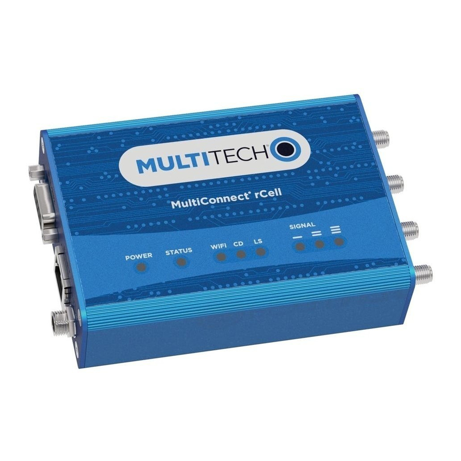
1- MultiConnect® rCell 100 Series Router (H5, H6, G3) 4.169" x 3.00" x 1.163" Blue enclosure includes:
|
|
Right Side Panel for MTR-H5 and MTR-H6

Right Side Panel for MTR-G3

Side Panels
The device has connectors on both sides of the housing. The right side of the device contains a reset button, WiFi, Auxiliary (for Diversity), GPS, and Cellular connectors for H5/H6. For G3, only the Cellluar connector is available. Depending on the model, GPS or WiFi connectors may or may not be present. The left side of the device includes an RS-232 connector, an Ethernet connector, and the power receptacle.
Installing the Router
- To use the router's cellular features, connect a suitable antenna to the antenna connector.
- Using an Ethernet cable, connect one end of the cable to the E-NET connector on the back of the router and the other end to your computer, directly or through a switch or hub.
- If you are connecting to a serial interface, connect the DE-9 connector (9-pin) of the RS-232 cable to the RS-232 connector on the router. Then connect the other end to the serial port on the desired device.
- Some routers support the use of a GPS receiver including B08 and B10 for H5 and B19 for H6. If you are using a GPS receiver with the router, attach the GPS cable to the GPS connector.
- Some routers support the use of WiFi including B09 and B10 for H5 and B18 and B19 for H6. If you are using WiFi with the router, attach the WiFi antenna to the WIFI connector.
- Screw on power lead from power supply module into power connection. Plug power supply into power source.
- POWER LED lights after the device powers up.
- When STATUS LED blinks, the device is ready for use.
- You can configure your device by using its web management interface. You may need to change the IP address of your computer to be in the same IP and subnet mask range as the device.
- Open web browser. In address field, type default address for the device: http://192.168.2.1. (If the browser displays a message about a problem with the security certificate, ignore and click Continue).
- For G3, a login page opens. Enter the default username: admin (all lower-case). Then, enter the default password: admin (all lower-case). Click Login.
- For H5/H6, when logging in for the first time, the device enters commissioning mode requiring a username and password for an admin user account. Enter and submit your desired username and password. Confirm the password.
- Refer to the appropriate user guide for further details on first-time setup.
Additional Information
For the latest information on your device including operation, regulatory, and safety topics, refer to the appropriate user guide online: http://www.multitech.com/brands/multiconnect-rcell-100-series
LED Descriptions
The top panel contains the following LEDs:
- Power and Status LEDs - The Power LED indicates that DC power is present and the Status LED blinks when the unit is functioning normally.
- WiFi LED - The WiFi LED indicates that WiFi is enabled (H5 and H6 only).
- Modem LEDs - Two modem LEDs indicate carrier detection and link status.
- Signal LEDs - Three signal LEDs display the signal strength level of the wireless connection.
- Ethernet LEDs - These LEDs are not on the top panel. The two Ethernet LEDs are physically on the RJ-45 connector(s).
- Ethernet Link LED - Located on the right on the Ethernet connector. This LED blinks when there is transmit and receive activity and is steady when there is a valid Ethernet connection.
- Ethernet Speed LED - Located on the left on the Ethernet connector. When lit the Ethernet is linked at 100Mbps. If it is not lit, the Ethernet is linked at 10 Mbps.
Installing a SIM Card
If you want to operate the router on a particular cellular network, install a mini-SIM card [or mini SIM (2FF) form factor].
To install the SIM:
- Locate the SIM card slot on the side of the router. The slot is labeled SIM.
- Push the SIM card into the slot until it snaps into place.


Mounting Device
- Locate the groove on the bottom of the modem.
- Slide the mounting rod through the groove.
- To secure the rod to the desired surface, place and tighten two screws in the holes on either end of the mounting rod. Refer to the user guide for an illustration of the mounting rod, as well as the dimensions for placement of the screws.
MultiConnect® rCell 100 Series Router(MTR-H5/H6/G3)
Part Number: 82102102L Rev. 3
Copyright and Trademarks
This publication may not be reproduced, in whole or in part, without the specific and express prior written permission signed by an executive officer of Multi-Tech Systems, Inc. All rights reserved. Copyright © 2018 by Multi-Tech Systems, Inc.
Multi-Tech Systems, Inc. makes no representations or warranties, whether express, implied or by estoppels, with respect to the content, information, material and recommendations herein and specifically disclaims any implied warranties of merchantability, fitness for any particular purpose and non-infringement. Multi-Tech Systems, Inc. reserves the right to revise this publication without obligation to notify any person or organization of such revisions or changes.
MultiConnect, MultiTech and the MultiTech logo are registered trademarks of Multi-Tech Systems, Inc. All other brand and product names are trademarks or registered trademarks of their respective companies.
47 CFR Part 15 Regulation Class B Devices
This equipment has been tested and found to comply with the limits for a Class B digital device, pursuant to part 15 of the FCC Rules. These limits are designed to provide reasonable protection against harmful interference in a residential installation. This equipment generates, uses, and can radiate radio frequency energy and, if not installed and used in accordance with the instructions, may cause harmful interference to radio communications. However, there is no guarantee that interference will not occur in a particular installation. If this equipment does cause harmful interference to radio or television reception, which can be determined by turning the equipment off and on, the user is encouraged to try to correct the interference by one or more of the following measures:
- Reorient or relocate the receiving antenna.
- Increase the separation between the equipment and receiver.
- Connect the equipment into an outlet on a circuit different from that to which the receiver is connected.
- Consult the dealer or an experienced radio/TV technician for help.

Changes or modifications to this unit not expressly approved by the party responsible for compliance could void the user's authority to operate the equipment.
EMC, Safety, and Radio Equipment Directive (RED) Compliance - H5 and H6
MultiTech declares that this device is in compliance with the essential requirements and other relevant provisions of Directive 2014/53/EU. The declaration of conformity may be requested at https://support.multitech.com.
Multi-Tech Systems, Inc.
2205 Woodale Drive, Mounds View, Minnesota 55112 U.S.A.
Phone: 763-785-3500 or 800-328-9717
Fax: 763-785-9874
Support
Support Portal
https://support.multitech.com
Knowledge Base
http://www.multitech.com/kb.go
Europe, Middle East, Africa:
support@multitech.co.uk
+(44) 118 959 7774
U.S., Canada, all others:
support@multitech.com
(800) 972-2439 or (763) 717-5863
Business Hours: M-F, 8am to 5pm CT

Documents / Resources
References
![www.multitech.com]() 4G LTE Cellular Routers | MultiConnect rCell 100 series
4G LTE Cellular Routers | MultiConnect rCell 100 seriesMultiTech Product Support Portal
![www.multitech.com]() Your Questions About IoT, Answered | MultiTech Knowledge Base
Your Questions About IoT, Answered | MultiTech Knowledge Base
Download manual
Here you can download full pdf version of manual, it may contain additional safety instructions, warranty information, FCC rules, etc.
Download Multitech MultiConnect rCell 100 Series, MTR-H5/H6/G3 Quick Start
Advertisement


Need help?
Do you have a question about the MultiConnect rCell 100 Series and is the answer not in the manual?
Questions and answers