Table of Contents
Advertisement
Quick Links
Advertisement
Table of Contents

Related Manuals for Multitech MA6


Summary of Contents for Multitech MA6
-
Page 1: Quick Start Guide
Model MA6 Single Processor Data and Fax Communications Server Quick Start Guide... - Page 2 82067052, Revision C...
-
Page 3: Table Of Contents
RASExpress & Auxiliary Software ... 6 Documentation Set Overview ... 8 Configurations ... 8 Technical Specifications ... 9 2 Installing Your MiniArray III Model MA6 Introduction ... 12 Unpacking ... 12 Safety Warnings: AC Power, Lithium Battery, Laser Caution, ... 12 Telecom Warnings ... -
Page 6: Introduction
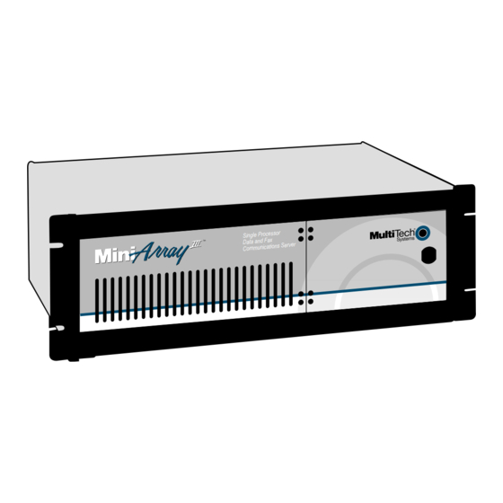
The heart of the MA6 is MultiTech's high-powered Pentium-based single-board computer (SBC) with up to 200 MHz of processing power. The MA6 has five expansion slots, four that meet the ISA standard, and one that accommodates either ISA or PCI devices. A user configurable card cage allows for up to 32 enhanced V.34 (33.6 bps) internal modems or up... - Page 7 Terminals Ethernet Concentrator Model EN516TP/CA Active Hub for UTP Networks Ethernet 10BASET Concentrator Printer Figure 1-2. Typical RASExpress Application • Support for DHCP, a time saving feature that dynamically allocates IP addresses instead of requiring network managers to allocate them manually •...
-
Page 8: Documentation Set Overview
Documentation Set Overview The MiniArray documentation set consists of this Quick Start Guide and a complete set of hardware and software manuals on CD-ROM. Updates are available from the Multi-Tech web site and FTP site. Manual Set Please refer to the list below for the individual titles included in your MiniArray documentation set. - Page 9 DC Output • Output: +5 @ 18A +12 @ 6A -5 @ 0.3A -12 @ 0.8A • Inrush Current<50A peak @ 115VAC, cold start at 25 • Line Regulation:+/- 5% at full load for +/-5V, +/-12V, +/-10% for -12V • Hold Time:20ms at full load @ 115VAC Dimensions •...
-
Page 12: Introduction
Check the items on the MiniArray options and accessories. Unpack and inspect the cabinet for visible shipping damage. If damage is observed, do not power-on the unit; contact Multi-Tech's Tech Support for advice. If no damage is observed, place the MiniArray Safety Warning AC Power Locate the AC outlet near the communication equipment. -
Page 13: Safety Warnings Telecom
Safety Warnings Telecom Never install telephone wiring during a lighting storm. Never install telephone jacks in wet locations unless the jack is specifically designed for wet locations. This product is to be used with UL and cUL listed computers. Never touch uninsulated telephone wires or terminals unless the telephone line has been disconnected at the network interface. -
Page 14: Sbc Board Cabling
SBC Board Cabling The SBC board is located in the MiniArray may involve connection to three back panel connectors (see Figure 2-2). The back panel connectors are: • Video connector • COM 1 connector • Keyboard connector The right connector on the SBC board connects the video cable to a monitor. The left round connector is for the keyboard. -
Page 15: Isi Board Cabling
ISI Board Cabling Each ISI3334/8 board takes up one physical slot in the MiniArray configuration, you may have a total of up to four (4) cards (see figure 2-1). Attach the RJ11 line cords to the RJ11 line connectors on the ISI card(s) at the back of your MiniArray shown in Figure 2-3. -
Page 16: Powering Up
Powering Up Note: This is plugable equipment; the socket outlet must be installed near the equipment and must be easily accessible. Make sure that the voltage selector on the power supply is set to the proper voltage prior to connecting this equipment to the main power. If the voltage selector needs to be changed, an ordinary pencil can be used to change the switch to the position which best correlates with the known input voltage. -
Page 18: Quick Start With Rasexpress
Quick Start with RASExpress What you need to start • The MiniArray • A dumb terminal or an auxiliary PC (other than the MiniArray terminal mode • A shielded RS-232C serial cable with a female DB-9 connector on one end and a connector to match the serial port of the terminal or auxiliary PC on the other end. - Page 19 Figure 3-1: Serial port on the MiniArray Note: The server takes a few moments to load the RASExpress software and to initialize the modems after it is turned on. Observe RAS software processing and displaying . Note: Error messages will appear and will indicate that the remote addresses of the WAN ports are not on the same subnet.
-
Page 20: Method B. Start Configuration With Terminal, Finish Configuration On Client Pc
i. From the terminal main menu, select Configuration of server ii. Select Communication Setup. iii. Select ISI Setup. iv. Delete all ISI cards before saving and rebooting the server. These steps correct the initial subnet error the next time the server loads. Method B. - Page 21 Figure 3-2: Serial port on the MiniArray Note: The server takes a few moments to load the RASExpress software and to initialize the modems after it si turned on.Observe RAS software processing and displaying . Note: Error messages will appear and will indicate that the remote addresses of the WAN ports are not on the same subnet.
- Page 22 Figure 3-3. Setup for completing RASExpress configuration from client PC • Dial in to the RASExpress server using a terminal program. A login prompt appears. • Enter a user name and password. A menu appears. • Select Telnet Session from the menu. •...
-
Page 24: Introduction
, and removing the MiniArray has been designed to make this process as efficient as possible, but if you experience problems, contact Multi-Tech Technical Support, refer to chapter 6 of this section. Disconnecting Cables and Removal from Enclosure The following table describes the procedures for removing the MiniArray enclosure. -
Page 25: Card Cage Removal/Replacement
If LAN is connected to the MiniArray Disconnect the telephone cords (RJ11) from the ISI board(s). Table 4.1 Cable Disconnection and Rack Enclosure Removal Procedure (cont'd.) It is recommended that two people remove the MiniArray Remove the four rack enclosure mounting screws from the front of MiniArray remove the MiniArray To re-attach cables and re-mount the MiniArray Card Cage Removal/Replacement... - Page 26 Step Procedure Remove the chassis mounting screw from the card cage. See Figure 4-4. Finish pulling the card cage (including fan enclosure) straight up and out of the chassis. See Figure 4-5. Set next to chassis. Before placing card cage back into chassis, verify that power connectors from the power Fig.
-
Page 27: Board Removal/Replacement
Board Removal/Replacement Step Procedure Removing SBC Board Remove the MiniArray Remove the top cover from the MiniArray screws located in the back of the MiniArray Disconnect the four ribbon cables from the SBC. (See Figure 4-6.) Depending on your configuration, you may not have all four ports in use. Fig. - Page 28 Remove the screw that secures the SBC board to the chassis at the back of the MiniArray Remove the SBC board from the midplane. To replace the SBC board, verify SBC board configuration; refer to the Hardware Configuration and Installation instructions in the SBC manual. Install the new SBC board by following steps 1-5 in reverse.
-
Page 29: Hard Disk Removal/Replacement
Being careful to maintain slack in the power cables, lift the card cage up and over so that it can rest along side the chassis. Remove the screw(s) that secures the ISI board(s) to the chasis at the back of the MiniArray Remove the ISI board(s) from the midplane. -
Page 30: Cdrom Removal/Replacement
Disconnect the power and data cables from the back of the floppy disk drive. Remove the four screws securing the floppy drive to the drive chassis. Open the front door, remove floppy drive by sliding it out the front of the drive chassis. - Page 31 Remove the top cover from the MiniArray screws located in the back of the MiniArray Remove the chassis mounting screw from the card cage. See figure 4-4. Partially remove the card cage and remove power cabling at midplane. Remove power cables from the back of hard drive, floppy drive, and CD ROM drive. Remove the three power supply mounting screws from the back of the MiniArray Remove the power supply from the chassis.
-
Page 34: Troubleshooting
Introduction This chapter provides steps for solving problems if the MiniArray thoroughly tested at the factory before it was shipped. If you are unable to make a successful connection, it is possible that the MiniArray source of your problem lies elsewhere. As with any microcomputer product, start with simple hardware and software problems, and then work toward more complex problems (i.e., operating system and/or applications). - Page 35 • Verify that SBC and adapter boards are seated properly in ISA slot. NOTE: Make sure to turn power off to reconnect boards. • Hard drive or floppy drive cables are not connected properly or parameters are not set properly in setup. •...
-
Page 36: Diagnostic Tests
These programs are available at any software re-seller and can quickly help isolate component failures. Calling Technical Support For immediate help in finding and fixing MiniArray call Multi-Tech's Technical Support department at 1-800-972-2439. problems, record the error condition and... -
Page 38: Introduction
Limited Warranty Multi-Tech Systems, Inc. (“MTS”) warrants that its products will be free from defects in material or workmanship for a period of two years from the date of purchase, or if proof of purchase is not provided, two years from date of shipment. MTS MAKES NO OTHER... -
Page 39: Warranty Addendum For Service On International Products
Multi-Tech has an excellent staff of technical support personnel available to help you get the most out of your Multi-Tech product. If you have any questions about the operation of this unit, call 1-800-972-2439. Please fill out the information (below), and have it available when you call. -
Page 40: About The Internet
About the Internet... - Page 41 Appendix A: Back Panel Connector Pinouts Appendix B: Regulatory Information Appendix C: Workstation Redirectors -- MCSIWSN and MINMCSI Appendix D: RADIUS Authentication & User Profile Software Appendix E: MultiManager Software...
-
Page 42: Appendix A: Back Panel Connector Pinouts
Appendix A: Back Panel Connector Pinouts Introduction This appendix provides specifications for the various connectors on the back panel of the MiniArray. VGA 15-Pin Connector This connector provides video analog data, and horizontal and vertical synchronization signals for VGA monitors. Figure A-1. - Page 43 9-Pin DB9 (COM 1) Connector This connector attaches the SBC board to the COM 1 serial port. Figure A-2. 9-Pin DB9 COM 1 Connector Pin Identification Description TX Data Ground 6-Pin Circular Jack This connector connects the keyboard to the SBC board. Figure A-3.
- Page 44 Ethernet NIC Card Connector RJ-45 Connector This connector ties the EN-Series Ethernet board to a 10BASET network. Figure A-5. RJ-45 Connector (viewed from connector side) Pin Identification Description + Transmit Data + Receive Data No Connect No Connect ISI Board Connector DB78S Connector This connector provides the serial, control and handshaking signals for all modems connected to the MiniArray.
- Page 45 Pin-out assignments for the 10Base-T connector are as follows: 10-pin Multi-Tech's products use a 10-pin 10Base-T connector. Some manufacturers use an 8-pin format. This format is compatible with the EN301CT16d, and will plug in and work without modification. If an 8-pin RJ-45 is used with the EN301CT16c, use the pin assignments shown in the 8-pin column.
-
Page 46: Hard Disk Connector
Printer Port Connector This 25-pin connector provides parallel printer data and control signals to and from the SBC board. COM 2 Port Connector This 10-pin connector transfers serial data to and from the COM 2 port. PinSignal Hard Disk Connector This connector supplies hard disk drive signals which interface with the software I/O drivers to provide the read/write functions. - Page 47 Figure A-7. Hard Disk Connector Description /Reset Ground (GND) Data Bit 7 (SD7) 23 Data Bit 8 (SD8) 24 Data Bit 6 (SD6) 25 Data Bit 9 (SD9) 26 Data Bit 5 (SD5) 27 Data Bit 10 (SD10) Data Bit 4 (SD4) 29 Data Bit 11 (SD11) Data Bit 3 (SD3) 31 Data Bit 12 (SD12)
-
Page 48: Appendix B Regulatory Information
7.No repairs are to be made by you. Repairs are to be made only by Multi-Tech Systems or its licensees. Unauthorized repairs void registration and warranty. -
Page 49: Canadian Limitations Notice
WARNING see instructions for use" with ports marked or not so marked may produce hazardous conditions on the network. Advice should be obtained from a competent engineer before such a connection is made. Multi-Tech Systems, Inc. ISI3334/4, ISI3334/EC and ISI3334/8 AU7USA-23834-MM-E 0.3B... - Page 50 It is a condition of approval that the power required by the host and the total of all adapter cards installed within the host environment, together with any auxiliary apparatus, does not exceed the power specification as stated in the Technical Reference Material of the host apparatus. The power requirements for the MULTIMODEMISI are: Modem operating voltages: Modem Power Consumption:...
-
Page 51: European Low Voltage Directive
• Operation in the absence of proceed indication • Automatic storage of last number dialed • Tone detection-busy • Auto clear from the originating end • DTR dialing • Modem • PBX timed break register recall European Low Voltage Directive When correctly installed and maintained, the modem will present no hazard to the user. - Page 52 external control software or external control apparatus which cause the operation of the modem associated call set-up equipment to contravene the requirements of the standard set out in BABT/SITS/82/005S/D. All other apparatus connected to this modem and thereby connected directly or indirectly to the British Telecom public switched telephone network must be approved apparatus as defined in Section 22 of the British Telecommunications Act 1984.
- Page 53 Modem CE Mark, EMC, and Safety Compliance The CE mark is affixed to the enclosed Multi-Tech product to confirm compliance with the following European Community Directives: Council Directive 89/336/EEC of 3 May 1989 on the approximation of laws of Member States relating to electromagnetic compatibility;...
- Page 54 Appendix C: Workstation Redirectors -- MCSIWSN and WINMCSI Introduction Installing MCSIWSN for DOS NTER NTER Using the MCSIWSN Redirector NTER Initializing, please wait... MCSI Program is resident NTER Enter your user name:...
-
Page 55: Appendix C: Workstation Redirectors
MCSIWSN Command Line Operation Unloads MCSIWSN. Searches for active modem servers. NTER Enter your password: NTER Login Completed. NTER NTER... - Page 56 Enables the command interpreter. An additional 5 KB of memory is used by MCSIWSN when the command interpreter is enabled. It allows applications programs that provide a command interpreter interface to issue the following commands: CONNECT, DISCONNECT, HELP, LIST, RESUME, SET, SHOW, SWITCH Connection Manager connects as inbound.
- Page 57 · · COMS14 Command Line Parameters Usage : coms14 -l [Server Name] (for listing services) : coms14 -c COM<n> <LineType> <SpecificName> <GeneralName> <ServerName> (for establishing a connection) : coms14 -d COM<n> (to disconnect) NTER Initializing, please wait... INT14 Program is Resident. NTER Enter your user name.
- Page 58 : coms14 -m ports) COMS14 -L [ServerName] Type coms14 -L for a list of available communications servers. Type coms14 -L [ServerName], e.g., coms14 -L server_1, for a list of services at an individual server similar to that shown below: List of services at the server SERVER_1 GENERAL NAME MODEM COMS14 -C COMn LineType SpecificName GeneralName ServerName...
-
Page 59: Installing And Configuring The Winmcsi Redirector
COMS14 -M Mapping of logical COM ports to network ports LOCAL PORT COM1 COM2 COM3 COM4 Installing and Configuring the WINMCSI Redirector WINMCSI Installation Windows 3.1, Windows for Workgroups 3.11, Windows95/98, or Windows NT: Windows 3.1 or Windows for Workgroups 3.11: 4a. -
Page 61: Running The Winmcsi Workstation Software
· · Note: If a serial mouse is connected to COM1, you must select a different local port. · · · Running the WINMCSI Workstation Software To log on to the communications server from a workstation If you want the first available line, click Map, then click Close, and go to the next section. -
Page 63: Appendix D: Radius Authentication & User Profile Software
Appendix D: RADIUS Authentication & User Profile Software Requirements Installing Radius Login Authentication Software... -
Page 65: Radius Software: "Clients" And "Users" Files
Radius Software: “Clients” and “Users” Files (i). Auth-Type. This field specifies whether the authentication is done locally or by the system (for WindowsNT only). Values: Local or System. (ii). Password = <The password of the particular user> Indicates that PAP is the authentication protocol. (iii). - Page 66 Indicates that CHAP protocol is the authentication protocol. (iv). Prefix and Suffix.
-
Page 67: Appendix E: Multimanager Introduction
Appendix E: MultiManager Introduction Multi-Tech MultiManager is a password-protected Windows 95/98/NT program for SNMP- based administration of RASExpress servers. It can be run from a network client PC or from a dial-in remote-node or remote-control PC. Using MultiManager you can: •... -
Page 68: Main Window
Main Window The main window is the control center for configuring and managing your RASExpress servers. Title Bar The title bar shows the IP address of the management workstation and the name and path of the active map file. Menu Bar The menu bar contains menus for controlling MultiManager itself, for configuring and managing your servers, for displaying statistics both numerically and graphically, and for editing network maps.
Need help?
Do you have a question about the MA6 and is the answer not in the manual?
Questions and answers