Table of Contents
Advertisement
Quick Links
TECHNICAL MANUAL
Of
Of Intel H610/Q670E Express Chipset
Based Micro-ATX M/B
No. G03-MM10-F
Rev: 1.0
Release date: November 29, 2022
Trademark:
* Specifications and Information contained in this documentation are furnished for information use only, and are subject
to change at any time without notice, and should not be construed as a commitment by manufacturer.
Advertisement
Table of Contents

Related Manuals for JETWAY MM10-H6100


Summary of Contents for JETWAY MM10-H6100
- Page 1 TECHNICAL MANUAL Of Intel H610/Q670E Express Chipset Based Micro-ATX M/B No. G03-MM10-F Rev: 1.0 Release date: November 29, 2022 Trademark: * Specifications and Information contained in this documentation are furnished for information use only, and are subject to change at any time without notice, and should not be construed as a commitment by manufacturer.
-
Page 2: Table Of Contents
TABLE OF CONTENT ENVIRONMENTAL SAFETY INSTRUCTION ................iii ENVIRONMENTAL PROTECTION ANNOUCEMENT .............. iii USER’S NOTICE ........................iv MANUAL REVISION INFORMATION ..................iv ITEM CHECKLIST ........................iv CHAPTER 1 INTRODUCTION OF THE MOTHERBOARD SPECIFICATION ......................1 LAYOUT DIAGRAM ....................3 CHAPTER 2 HARDWARE INSTALLATION JUMPER SETTING ..................... -
Page 3: Environmental Safety Instruction
Environmental Safety Instruction ⚫ Avoid the dusty, humidity and temperature extremes. Do not place the product in any area where it may become wet. ⚫ 0 to 40 centigrade is the suitable temperature. (The figure comes from the request of the main chipset) ⚫... -
Page 4: User's Notice
USER’S NOTICE COPYRIGHT OF THIS MANUAL BELONGS TO THE MANUFACTURER. NO PART OF THIS MANUAL, INCLUDING THE PRODUCTS AND SOFTWARE DESCRIBED IN IT MAY BE REPRODUCED, TRANSMITTED OR TRANSLATED INTO ANY LANGUAGE IN ANY FORM OR BY ANY MEANS WITHOUT WRITTEN PERMISSION OF THE MANUFACTURER. -
Page 5: Chapter 1 Introduction Of The Motherboard
CPU Socket 65W TDP) *Note: for detailed CPU support information please visit our website ⚫ MM10-H6100/6102 series: 2* Long DIMM DDR5 slot for 2* DDR5 up to 4800MHz RAM Module ⚫ MM10-Q6700/6702 series: 4* Long DIMM DDR5 slot for 4* DDR5... - Page 6 ⚫ 1* COM (RS232/422/485) ⚫ 1* 3-jack audio connector (Line-in, Line-out, MIC) ⚫ MM10-H6100/6102 Series: 2* USB 3.2 (Gen.2) + 4* USB 2.0 ⚫ MM10-Q6700/6702 Series: 6* USB 3.2 (Gen.2) Internal I/O Connectors & Headers: ⚫ 1* 24-pin main power connector ⚫...
-
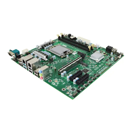
Page 7: Layout Diagram
USB 3.2 (Gen.2) Ports Ports MM10-Q6700/6702 Series: RJ-45 LAN Ports (1GbE) RJ-45 LAN Ports COM1 (2.5GbE) Serial Port HDMI Ports Audio Connector DisplayPort USB 3.2 (Gen.2) USB 2.0 Ports Ports *Note: COM1 support RS232/422/485 function for both MM10-H6100/6102 Series and MM10-Q6700/6702 Series. - Page 8 Motherboard Internal Diagram MM10-H6100/6102 Series: ATX 12V Power CPU FAN Connector Connector SYSFAN1 VGA Header DDR5 UDIMM Slots x2 *Rear IO Connector ATX Power (Refer to Page-2) Connector M.2 M-Key Slot USB 3.2 (Gen.1) Header Type-2242/2260/2280/22110 (SATA) (USB3) SATAIII DOM Port...
- Page 9 MM10-Q6700/6702 Series: ATX 12V Power CPU FAN Connector Connector SYSFAN1 VGA Header DDR5 UDIMM Slots x4 *Rear IO Connector (Refer to Page-2) ATX Power Connector M.2 M-Key Slot USB 3.2 (Gen.1) Header Type-2242/2260/2280/22110 (USB3) (SATA/PCIe 4.0x4) SATAIII DOM Port PCIE1: PCIe 5.0 x16 slot (SATA2) PCIE2: PCIe 4.0 x4 slot SMBUS Header...
- Page 10 Motherboard Jumper Position: JBAT1 COPEN JAT_ATX *Note: The diagrams in the manual are mostly taken from MM10-Q6700/6702 series unless otherwise stated. Jumper Jumper Name Description Pitch JBAT1 Clear CMOS RAM Settings 3-pin Block 2.0mm JAT_ATX ATX/AT Mode Select 3-pin Block 2.54mm COPEN Case Open Message Display Detect...
- Page 11 (Max Resolution: 4096x2160@60Hz) Top: 1GbE RJ-45 Port X1 Middle & Bottom: USB 3.2 (Gen.2) Port X2 Top: 1GbE RJ-45 LAN Port X1 Middle & Bottom: USB 2.0 Port X2 (MM10-H6100/6102) USB 3.2 (Gen.2) Port X2 (MM10-Q6700/6702) MM10-H6100/6102: USB 2.0 Port X2 MM10-Q6700/6702: Top: 2.5GbE RJ-45 Port X1...
-
Page 12: Chapter 2 Hardware Installation
Chapter 2 Hardware Installation 2-1 Jumper Setting JBAT1 (3-pin): Clear CMOS Pitch=2.0mm JBAT1 JAT_ATX (3-pin): ATX Mode/AT Mode Select Pitch=2.54mm JAT_ATX *ATX Mode Selected: Press power button to power on after power input ready; AT Mode Selected: Directly power on as power input ready. COPEN (2-pin): Case Open Message Display Function Pitch=2.54mm COPEN CASE OPEN... - Page 13 Pin 1-2 Short: When Case open function pin short to GND, the Case open function was detected. When Used, needs to enter BIOS and enable ‘Case Open Detect’ function. In this case if your case is removed, next time when you restart your computer, a message will be displayed on screen to inform you of this.
-
Page 14: Connectors And Headers
JP4 (2-pin): GPIO/80 PORT MODE Select Pitch2.0mm 2-2 Connector and Headers 2-2-1 Rear I/O Back Panel Connectors *Refer to Page-2 Rear IO Diagram Icon Name Function Mainly for user to connect external MODEM or other Serial Port devices that supports Serial Communications Interface. HDMI 2.0 Port To connect display device that support HDMI specification. -
Page 15: Motherboard Internal Connectors
BLUE: Line-in Connector Audio Connectors GREEN: Line-out Connector PINK: MIC Connector COM1 (9-pin Block): Serial Port The pin assignment for RS232/422/485 is listed as follows: Pin1 Pin1 Pin1 1 2 3 4 5 RS422 Mode RS485 Mode (MM21-Q4700/Q4702 Series) (MM21-Q4700/Q4702 Series) 6 7 8 9 RS232 Mode (MM21-Q4700/Q4702 Series... - Page 16 into the connector with ease only in the right direction. If the direction is wrong it is hard to fit in and if you make the connection by force if is possible. ATXPWR1 Figure1:20-pin power plug Figure 2:24-pin power plug (2) ATX12V1(8-pin): 12V Power Connector This is a new defined 8-pin connector that usually comes with ATX Power Supply.
- Page 17 (3) CPUFAN1 (4-pin): CPU Fan Connector CPUFAN1 *Note: Maximum current limit is 0.5A while using 5V working voltage (4) SYSFAN1/2 (3-pin): System Fan 1 & 2 Connectors SYSFAN1 SYSFAN2 *Note: Maximum current limit is 0.5A while using 5V working voltage (5) SATA2/3/4 (7-pin): SATAIII Port Connectors These are high-speed SATAIII ports that support 6GB/s transfer rate.
- Page 18 (6) Dual Channel Memory Installation Configuration DIMM1 DIMM2 DIMM3 DIMM4 install install install install install install install Notice! ⚫ For dual channel installation, you need to install the same brand, speed, size and type memory module. *Please follow the instruction above to prioritize DIMM2 slot when installing one or two memory modules.
-
Page 19: Header Pin Definition
USB3 *Note: Maximum current limit is 1.5A while using 5V working voltage (3) FP_USB2~FP_USB5 (9-pin): USB 2.0 Port Header Pitch=2.0mm Pin1 FP_USB3 FP_USB2 FP_USB4 FP_USB5 *Note: Maximum current limit is 1.5A while using 5V working voltage. MM10-H6100/6102 only has FP_USB4/5. - Page 20 (4) FP_USB6 (4-pin): USB 2.0 Port Header Pitch=2.0mm FP_USB6 *Note: Maximum current limit is 1.5A while using 5V working voltage (5) FP_Audio (10-pin): Front Panel Audio Header Pitch=2.0mm Pin1 FP_AUDIO (6) COM7-10 (35-pin): Reserved Serial Port (support RS232) Pitch=2.0mm *Note: COM7-10 ports are optional and by request only COM7-10 PinB1 PinA1...
- Page 21 COM7-10 Pin NO RS232 Pin NO. RS232 Pin A1 DCD7 Pin B1 DSR7 Pin A2 SIN7 Pin B2 RTS7 COM7 Pin A3 SOUT7 Pin B3 CTS7 Pin A4 DTR7 Pin B4 Pin A5 Pin B5 Pin A6 DCD8 Pin B6 DSR8 Pin A7 SIN8...
- Page 22 Please refer to Page-10 JP4 jumper setting for GPIO header GPIO Port or 80 Note Port function select: Pin 1&2 of JP4 Open: or 80Port Function; Pin 1&2 of JP4 Closed: For Normal 8-bit GPIO Function (8) PS2KBMS (6-pin): PS/2 Keyboard & Mouse Header Pitch=2.54mm PS2KBMS *Note: Maximum current limit is 500mA while using 5V working voltage (9) SMBUS1 (5-pin): SMBUS Header Pitch=2.0mm...
- Page 23 (11) HDMI_SPDIF (2-pin): HDMI SPDIF Out Header Pitch=2.54mm HDMI_SPDIF 2-2-4 Maximum Voltage & Current Limit Below is a list of maximum voltage & Current Limit specification for motherboard interface (including but not limited to slots, connectors, wafers and headers) for setup reference: Location Function...
-
Page 24: Chapter 3 Introducing Bios
Chapter 3 Introducing BIOS Notice! The BIOS options in this manual are for reference only. Different configurations may lead to difference in BIOS screen and BIOS screens in manuals are usually the first BIOS version when the board is released and may be different from your purchased motherboard. Users are welcome to download the latest BIOS version form our official website. -
Page 25: Bios Menu Screen
3-2 BIOS Menu Screen The following diagram show a general BIOS menu screen: Menu Bar General Help Items Current Setting Value Menu Items Function Keys 3-3 Function Keys In the above BIOS Setup main menu of, you can see several options. We will explain these options step by step in the following pages of this chapter, but let us first see a short description of the function keys you may use here: ⚫... -
Page 26: Getting Help
3-4 Getting Help Main Menu The on-line description of the highlighted setup function is displayed at the top right corner the screen. Status Page Setup Menu/Option Page Setup Menu Press 【 F1 】 to pop up a small help window that describes the appropriate keys to use and the possible selections for the highlighted item. -
Page 27: Advanced Menu
System Time Set the time. Please use [Tab] to switch between time elements. 3-7 Advanced Menu For MM10-Q670 For MM10-H610... - Page 28 Connectivity Configuration Use this item to configure connectivity related options Press [Enter] to make settings for the following sub-items: CNVi Mode This item configures connectivity. The optional settings: [Disable Integrated]; [Auto Detection]. [Disable Integrated]: it disables Integrated Solution. [Auto Detection]: if discrete solution is discovered it will be enabled by default. Otherwise integrated solution (CNVi) will be enabled.
- Page 29 The optional settings: [Disabled]; [Enabled]. Hot Plug Use this item to designate this port as Hot Pluggable. The optional settings: [Disabled]; [Enabled]. SATA3 Port Use this item to enable or disable SATA port. The optional settings: [Disabled]; [Enabled]. Hot Plug Use this item to designate this port as Hot Pluggable.
- Page 30 MAC Pass Through Use item to enable/disable MAC Pass Through. Function The optional settings are: [Disabled]; [Enabled]. Activate Remote Assistance Process Use this item to trigger CIRA boot. *Note: Network Access must be activated first from MEBx Setup. The optional settings are: [Disabled]; [Enabled]. Unconfigure ME Unconfigure ME with tesetting MEBx password to defsult on next boot.
- Page 31 Active PCR banks Available PCR banks SHA256 PCR Bank Use this item to enable or disable SHA256 PCR Bank The optional settings are: [Disabled]; [Enabled]. SHA384 PCR Bank Use this item to enable or disable SHA384 PCR Bank The optional settings are: [Disabled]; [Enabled]. SM3_256 PCR Bank Use this item to enable or disable SM3_256 PCR Bank The optional settings are: [Disabled];...
- Page 32 Only Disable ERP Function The optional settings are: [Disabled]; [Enabled]. PCIE Wake-up from S3-S5 The optional settings are: [Disabled]; [Enabled]. USB S3/S4 Wake-up Use this item to enable or disable USB wake-up from S3/S4 state. *This function is supported when ‘ERP Support’ is set as [Disabled]. The optional settings are: [Enabled];...
- Page 33 ► Serial Port 3 Configuration Press [Enter] to make settings for the following items: Serial Port Use this item to enable or disable serial port (COM). The optional settings are: [Disabled]; [Enabled]. *When set as [Enabled], user can make further settings in the following items: Change Settings Use this item to select an optimal setting for super IO device.
- Page 34 WatchDog Reset Timer Use this item to enable or disable WDT reset function. *When set as [Enabled], the following sub-items shall appear: WatchDog Reset Timer Value User can set a value in the range of [4] to [255]. WatchDog Reset Timer Unit The optional settings are: [Sec.];...
- Page 35 user is using) will exchange data. Both computers should have the same or compatible settings. Press [Enter] to make settings for the following items: COM1 Console Redirection Settings Terminal Type The optional settings are: [VT100]; [VT100 Plus]; [VT-UTF8]; [ANSI]. Emulation: [ANSI]: Extended ASCII char set; [VT100]: ASCII char set; [VT100 Plus]: Extends VT100 to support color, function keys, etc.;...
- Page 36 Legacy Console Redirection Settings Press [Enter] to make settings for the following items: Redirection COM Port Use this item to select a COM port to display redirection of Legacy OS and Legacy OPROM Messages. The optional settings are: [COM1] Resolution Use this item to on Legacy OS, the Number of Rows and Columns supported redirection...
- Page 37 Stop Bits The default setting is: [1]. *This item may or may not show up, depending on different configuration. USB Configuration Press [Enter] to make settings for the following sub-items: USB Configuration XHCI Hand-off This is a workaround for OSes without XHCI hand-off support. The XHCI ownership change should be claimed by XHCI driver.
-
Page 38: Chipset Menu
Use either [+] / [-] or numeric keys to set the value. NVMe Configuration Press [Enter] to view current NVMe Configuration. *Note: options only when NVME device is available. Intel® Ethernet Controller I225-V- XX:XX:XX:XX:XX:XX Use this item to for MM10-Q670 ... - Page 39 Primary Display Use this item to select which of graphics device should be Primary Display. The optional settings are: [Auto]; [IGFX]; [PEG Slot]; [PCH PCIE] Internal Graphics Use this item to keep IGFX enabled based on the setup options. The optional settings are: [Auto]; [Disable]; [Enable]. Aperture Size Use this item to select the Aperture Size.
-
Page 40: Security Menu
Note: Use this item to for MM10-Q670 System State After Power Failure Use this item to select what state to go to when power is re-applied after a power failure (G3 state). The optional settings are: [Always On]; [Always Off]; [Former State]. 3-9 Security Menu Security menu allow users to change administrator password and user password settings. -
Page 41: Boot Menu
Set UEFI Secure Boot Mode to Standard mode or Custom mode. In Custom mode, Secure Boot Policy variables can be configured by a physically present user without full authentication. The optional settings are: [Standard]; [Custom]. *When set as [Custom], user can make further settings in the following items that show up: ... -
Page 42: Save & Exit Menu
Boot Configuration Setup Prompt Timeout Use this item to set number of seconds to wait for setup activation key. Bootup Numlock State Use this item to select keyboard numlock state. The optional settings are: [On]; [Off]. Quiet Boot Use this item to enable or disable quiet boot option. The optional settings are: [Disabled];... - Page 43 Save Changes and Reset This item allows user to reset the system after saving the changes. Discard Changes and Reset This item allows user to reset the system without saving any changes. Default Options Restore Defaults Use this item to restore /load default values for all the setup options. Save as User Defaults Use this item to save the changes done so far as user defaults.
Need help?
Do you have a question about the MM10-H6100 and is the answer not in the manual?
Questions and answers