Table of Contents
Advertisement
Quick Links
USER'S MANUAL
Of
AMD 790X & AMD SB600
AMD 770 & AMD SB600
Based
M/B For Socket AM2+ 64-bit Quad Core
AMD Processor
NO. G03-HA03 -F
:
Rev
3.0
Release date: JAN. 2008
Trademark:
* Specifications and information contained in this documentation are furnished for information use only, and are
subject to change at any time without notice, and should not be construed as a commitment by manufacturer.
Advertisement
Table of Contents

Related Manuals for JETWAY HA03


Summary of Contents for JETWAY HA03
- Page 1 AMD 770 & AMD SB600 Based M/B For Socket AM2+ 64-bit Quad Core AMD Processor NO. G03-HA03 -F : Release date: JAN. 2008 Trademark: * Specifications and information contained in this documentation are furnished for information use only, and are...
- Page 2 Environmental Protection Announcement Do not dispose this electronic device into the trash while discarding. To minimize pollution and ensure environment protection of mother earth, please recycle.
-
Page 3: Table Of Contents
TABLE OF CONTENT USER’S NOTICE........................iii MANUAL REVISION INFORMATION ................iii COOLING SOLUTIONS ......................iii CHAPTER 1 INTRODUCTION OF AMD 790X/770 CROSSFIREX MOTHERBOARDS FEATURES OF MOTHERBOARD ..................1 1-1.1 SPECIAL FEATURES OF MOTHERBOARD............ 2 SPECIFICATION........................3 PERFORMANCE LIST......................4 LAYOUT DIAGRAM & JUMPER SETTING ..............5 CHAPTER 2 HARDWARE INSTALLATION HARDWARE INSTALLATION STEPS................ -
Page 4: User's Notice
USER’S NOTICE COPYRIGHT OF THIS MANUAL BELONGS TO THE MANUFACTURER. NO PART OF THIS MANUAL, INCLUDING THE PRODUCTS AND SOFTWARE DESCRIBED IN IT MAY BE REPRODUCED, TRANSMITTED OR TRANSLATED INTO ANY LANGUAGE IN ANY FORM OR BY ANY MEANS WITHOUT WRITTEN PERMISSION OF THE MANUFACTURER. THIS MANUAL CONTAINS ALL INFORMATION REQUIRED TO USE NF6100-400 / 405 PPC MOTHERBOARD AND WE DO ASSURE THIS MANUAL MEETS USER’S REQUIREMENT BUT WILL CHANGE, CORRECT ANY TIME WITHOUT NOTICE. - Page 5 Chapter 1 Introduction of AMD 790X/770 CrossFire Motherboards Features of motherboard The AMD 790X/770 CrossFire chipset motherboard series are based on the latest AMD 790X /770 CrossFire Chipset and the SB600 chipset which supports the innovative 64-bit AMD Socket AM2+ dual core multi-tasking Socket AM2+ Athlon64 X2 processors. With an integrated low-latency high-bandwidth DDRII memory controller and a highly-scalable Hyper Transport technology-based system bus up to 2.0 GHZ.
-
Page 6: Features Of Motherboard
peripheral devices. Embedded USB controllers as well as capability of expanding to 10 of USB2.0 functional ports delivering 480Mb/s bandwidth of rich connectivity, these motherboards meet the future USB demands which are also equipped with hardware monitor function on system to monitor and protect your system and maintain your non-stop business computing. - Page 7 time wasted in the first moment of 24-hour nonstop ping business computing, the embedded Debug Port will turn you into a well training hardware professional with the seeing system situation. (The Post Code please refer to appendix) OC-CON ---(High-polymer Solid Electrolysis Aluminum Capacitors) The working temperature is from 55 degrees Centigrade below zero to 125 degrees Centigrade, OC-CON capacitors possess superior physical characteristics that can be while reducing the working temperature between 20 degrees Centigrade each time, intact extension...
-
Page 8: Specification
Specification Spec Description ∗ ATX form factor 4 layers PCB size: 30.5cm*24.5cm Design * AMD 790X/770 CrossFire North Bridge Chipset Chipset * AMD SB600 South Bridge Chipset ∗ Support 64bit AMD Athlon64 940-Pin package utilizes Flip-Chip Pin Grid Array package processor ∗... -
Page 9: Performance List
Performance List The following performance data list is the testing result of some popular benchmark testing programs. These data are just referred by users, and there is no responsibility for different testing data values gotten by users (the different Hardware & Software configuration will result in different benchmark testing results.) Performance Test Report AMD K8 Sempron2800+... -
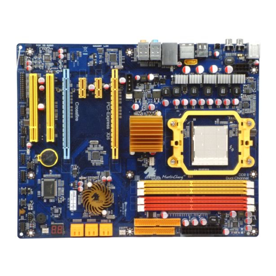
Page 10: Layout Diagram & Jumper Setting
Layout Diagram & Jumper Setting Line-IN RJ45 LAN ESATA Surrback Line-OUT SPDIF OUT CMOS2 PS/2 Mouse CEN/BASS PS/2 Keyboard Surround MIC-IN SPDIF IN KBMB/USB Power On(JP1) ATX 12V Power Connector PS2 KB/Mouse Port SPDIF OUT DDR2 Socket x 4 SPDIF IN CMOS2 Serial-ATAII USB Port... - Page 11 Jumpers Jumper Name Description Page Keyboard/USB Power On Enabled/Disabled 3-pin Block Connectors Connector Name Description Page ATXPWR1 ATX Power Connector 24-pin Block P.11 ATX12V1 ATX 12V Power Connector 8-pin Block P.12 PS/2 Mouse & PS/2 Keyboard Connector 6-pin Female P.12 CN1 for USB USB2.0 Port Connector 4-pin Connector...
-
Page 12: Chapter 2 Hardware Installation
Chapter 2 Hardware Installation WARNING! Turn off your power when adding or removing expansion cards or other system components. Failure to do so may cause severe damage to both your motherboard and expansion cards. Hardware installation Steps Before using your computer, you had better complete the following steps: 1. -
Page 13: About Amd Athlon64 Socket Am2+ Cpu
scanners, and some digital cameras. Sound (interface) - the interface between the sound card or integrated sound connectors and speakers, MIC, game controllers, and MIDI sound devices. LAN (interface) - Local Area Network - the interface to your local area network. BIOS (Basic Input/Output System) - the program logic used to boot up a computer and establish the relationship between the various components. -
Page 14: Install Memory
Install Memory This motherboard provides four 240-pin DDR2 DUAL INLINE MEMORY MODULES (DIMM) socket for DDR2 memory expansion available from minimum memory volume of 128MB to maximum memory volume of 8.0GB DDRII SDRAM. Valid Memory Configurations Bank 240-Pin DIMM Total Memory Bank 0, 1 (DIMM1) DDR2 667/DDR2 800/ DDR2 1066 * 128MB∼2.0GB... -
Page 15: Expansion Cards
Expansion Cards 2-5-1 Procedure For Expansion Card Installation 1. Read the documentation for your expansion card and make any necessary hardware or software setting for your expansion card such as jumpers. 2. Remove your computer’s cover and the bracket plate on the slot you intend to use. 3. -
Page 16: Pci-Express2.0 Slot
2-5-4 PCI Express Slot Two PCI-Express2.0 x16@8 line graphics slot offer 4 Gbyte/sec data transfer rate at each relative direction and up to 8 Gbyte/sec concurrent bandwidth at full speed. With two switch cards installed to activate the CrossFire mode, these two slots deliver up to 16Gbyte/sec data transfer rate concurrently. -
Page 17: Connectors, Headers
2-6 Connectors, Headers 2-6-1 Connectors Power Connector (24-pin block) : ATXPWR1 ATX Power Supply connector: This is a new defined 24-pins connector that usually comes with ATX case. The ATX Power Supply allows using soft power on momentary switch that connect from the front panel switch to 2-pins Power On jumper pole on the motherboard. - Page 18 (4) USB Port connector: CN1/CN2/UL1 for USB The connectors are 4-pin connector that connects USB devices to the system board. (5) LAN Port connector: UL1 for RJ45 LAN This connector is standard RJ45 connector for Network. It supports 10M/100Mb/1000Mb s data transfer rate (6) J2 Power Connector: Large 4-Pin Power Connector The connectors are 4-pin connector that supports extra 12V / 5V power to your system...
- Page 19 Pin 1 Floppy Drive Connector (9) Primary IDE Connector (40-pin block): IDE1 This connector supports the provided IDE hard disk ribbon cable. After connecting the single plug end to motherboard, connect the two plugs at other end to your hard disk(s). If you install two hard disks, you must configure the second drive to Slave mode by setting its jumpers accordingly.
-
Page 20: Headers
This connector supports the provided Serial ATA2 IDE hard disk cable to connecting the motherboard with serial ATAII hard disk. E-SATA1 is not for SATA hard drive, it is only for connecting to SATA1, SATA2, D-SATA1, or D-SATA2 to let the ESATA port work. - Page 21 (2) USB Port Headers (9-pin): USB1/USB2 These headers are used for connecting the additional USB port plug. By attaching an option USB cable, your can be provided with two additional USB plugs affixed to the back panel. USB2 USB1 Pin 1 Pin 1 USB Port Headers (3) Speaker connector: SPEAKER...
- Page 22 CPUFAN SYSFAN2 SYSFAN1 CHAFAN FAN Power Headers (9) CD Audio-In Headers (4-pin): CDIN1 CDIN are the connectors for CD-Audio Input signal. Please connect it to CD-ROM CD-Audio output connector. C DIN CD Audio-In Headers (10) IR infrared module Headers (5-pin): IR This connector supports the optional wireless transmitting and receiving infrared module.
- Page 23 Pin 1 PARALLEL Connector (12) Serial COM Port header: COM1 COM1 is the 9-pin block pin-header. The On-board serial port can be disabled through BIOS SETUP. Please refer to Chapter 3 “INTEGRATED PERIPHERALS SETUP” section for more detail information. Pin1 Serial COM Port 9-pin Block (13) HDMI-SPDIF Out header: SPDIF Out The SPDIF output is capable of providing digital audio to external speakers or compressed...
-
Page 24: Starting Up Your Computer
Starting Up Your Computer 1. After all connection are made, close your computer case cover. 2. Be sure all the switch are off, and check that the power supply input voltage is set to proper position, usually in-put voltage is 220V∼240V or 110V∼120V depending on your country’s voltage used. -
Page 25: Chapter 3 Introducing Bios
Chapter 3 Introducing BIOS The BIOS is a program located on a Flash Memory on the motherboard. This program is a bridge between motherboard and operating system. When you start the computer, the BIOS program will gain control. The BIOS first operates an auto-diagnostic test called POST (power on self test) for all the necessary hardware, it detects the entire hardware device and configures the parameters of the hardware synchronization. -
Page 26: The Main Menu
The Main Menu Once you enter Award ® BIOS CMOS Setup Utility, the Main Menu (Figure 3-1) will appear on the screen. The Main Menu allows you to select from fourteen setup functions and two exit choices. Use arrow keys to select among the items and press <Enter> to accept or enter the sub-menu. -
Page 27: Standard Cmos Features
This menu uses a minimal performance setting, but the system would run in a stable way. Load Optimized Defaults Use this menu to load the BIOS default values these are setting for optimal performances system operations for performance use. Save & Exit Setup Save CMOS value changes to CMOS and exit setup. -
Page 28: Advanced Bios Features
If the controller of HDD interface is SCSI, the selection shall be “None”. If the controller of HDD interface is CD-ROM, the selection shall be “None” Access Mode The settings are Auto Normal, Large, and LBA. Cylinder number of cylinders Head number of heads Precomp... - Page 29 Quick Power On Self-Test This category speeds up Power On Self Test (POST) after you power on the computer. If this is set to Enabled, BIOS will shorten or skip some check items during POST. Enabled (default) Enable quick POST Disabled Normal POST First/Second/Third/Fourth Boot Device...
-
Page 30: Advanced Chipset Features
Advanced Chipset Features The Advanced Chipset Features Setup option is used to change the values of the chipset registers. These registers control most of the system options in the computer. Phoenix – AwardBIOS CMOS Setup Utility Advanced Chipset Features PCIE Configuration [press enter] Item Help Memory Hole... -
Page 31: Integrated Peripherals
Active State Power Management Support Link Width: PCI Express slot link bandwidth: x1, x2, x4, x8, x16 lanes. Slot Power Limit, W: Please refer above mention. GPP1/GPP2/GPP5/GPP6 Press Enter and you can modify tow items:Gen2 High Speed Mode and Link Aspm. Please refer to the above explanation. -
Page 32: Onchip Ide Funtion
UART Mode Select This item allows you to determine which InfraRed(IR) function of the onboard I/O chip, this functions uses. IrDA Duplex Mode This field is available when UART Mode is set to either ASKIR or IrDA. This item enables you to determine the infrared function of the onboard infrared chip. -
Page 33: Onchip Pci Device
IDE DMA transfer access The integrated peripheral controller contains an IDE interface with support for one IDE channels. Select Enabled to activate each channel separately. The settings are: Enabled and Disabled. Primary Master/Slave PIO The two IDE PIO (Programmed Input/Output) fields let you set a PIO mode (0-2) for each of the two IDE devices that the onboard IDE interface supports. -
Page 34: Power Management Setup
Power Management Setup The Power Management Setup allows you to configure your system to most effectively save energy saving while operating in a manner consistent with your own style of computer use. Phoenix – AwardBIOS CMOS Setup Utility Power Management Setup ACPI function Enabled Item Help... -
Page 35: Miscellaneous Configuration
You can choose which month the system will boot up. Set to 0, to boot every day. Time (hh:mm:ss) You can choose what hour, minute and second the system will boot up. Note: If you have changed the setting, you must reset your computer until it goes to the operating system, before this function will work. -
Page 36: Pc Health Status
3-10 PC Health Status This section shows the Status of you CPU, Fan, and Warning for overall system status. This is only available if there is Hardware Monitor onboard. Phoenix – AwardBIOS CMOS Setup Utility PC Health Status Show PC Health in Post Enabled Item Help Shutdown Temperature... -
Page 37: Power User Overclock Setting
3-11 Power User Overclock Setting Phoenix – AwardBIOS CMOS Setup Utility Power User Overclock Setting CPU/HT Reference Clk(MHz) [200] Item Help AMD CPU Ratio Control Auto PCIE Reference Clock [100] 【 100 】 SB Refence Clock CPU/HT Reference Clk Memory Clock Mode Auto Min=190 *Memory Clock Value or limit DDR... - Page 38 Phoenix – AwardBIOS CMOS Setup Utility Power User Overclock Setting VDIMM Select CPU/HT Reference Clk(MHz) [200] Item Help AMD CPU Ratio Control Auto 1.70v... [ ] PCIE Reference Clock [100] 【 100 】 SB Refence Clock 1.75v... [ ] Menu Level > Memory Clock Mode Auto 1.80v ......
- Page 39 Phoenix – AwardBIOS CMOS Setup Utility Power User Overclock Setting CPU/HT Reference Clk(MHz) [200] PCIE Reference Clock AMD CPU Ratio Control Auto Item Help PCIE Reference Clock [100] Min = 90 【 100 】 SB Refence Clock Max =250 Memory Clock Mode Auto Menu Level >...
-
Page 40: Ht Link Control
3-11-1 HT Link Control Phoenix – AwardBIOS CMOS Setup Utility HT link Control HT link Width Auto Item Help HT link Frequency Auto IH Flow Control Mode Disabled HT link Trislate Disabled Menu Level > 2xLclk Mode Disabled Unit ID Clumping Disabled ↑↓→←... -
Page 41: Cpu Feature
3-11-2 CPU Feature Phoenix – AwardBIOS CMOS Setup Utility CPU Feature Virtualization Enabled Item Help AMD K8 Cool & Quiet Control Disabled Menu Level > ↑↓→← Move Enter:Select +/-/PU/PD:Value F10:Save ESC:Exit F1:General Help F5:Previous Values F6:Fail-safe Defaults F7:Optimized Defaults 3-11-3 DRAM Configuration Phoenix –... -
Page 42: Cpu Thermal Throttling Options
gives faster performance; and Slow gives more stable performance. This field applies only when synchronous DRAM is installed in the system. 3-12 Thermal Throttling Options Phoenix – AwardBIOS CMOS Setup Utility Thermal Throttling Options CPU Thermal-Throttling Disabled Item Help CPU Throttling Temp CPU Thermal-Throttling Menu Level >... - Page 43 password. ENTER PASSWORD: Type the password, up to eight characters in length, and press <Enter>. The password typed now will clear any previously entered password from CMOS memory. You will be asked to confirm the password. Type the password again and press <Enter>. You may also press <Esc> to abort the selection and not enter a password.
-
Page 44: Chapter 4 Driver & Free Program Installation
Chapter 4 DRIVER & FREE PROGRAM INSTALLATION Check your package and there is A MAGIC INSTALL CD included. This CD consists of all DRIVERS you need and some free application programs and utility programs. In addition, this CD also include an auto detect software which can tell you which hardware is installed, and which DRIVERS needed so that your system can function properly. -
Page 45: Ati Install Ati Driver Pack
4-1 Install ATI Driver Pack 1. Click ATI in the MAGIC INSTALL MENU 2. Click NEXT when ATI software driver pack appears. appears. 3. Click “Yes” to accept the license agreement 4. Click Finish to restart your computer and start installation.. The path of the file is X:\ATI \DRIVER\SETUP.EXE SOUND Install ALC888 HD Codec Audio Driver... -
Page 46: Lan Install Tealtek Lan Controller Driver
3. Click FINISH and restart your computer 4. Manual Sound Effect Setting 5. Devices and mixer setting 6. Audio input and output setting. 7. Microphone effect setting. 8. 3D demo setting. NOTE: Please upgrade your Windows XP to Service Pack 2 / Windows 2000 to Service Pack 4 or later before you the HD Audio CODEC driver. -
Page 47: Usb
3. Click “ I accept the agreement” and then click 4.Click Install to begin the installation. Next. 5. The installation process. 6.After driver installation completed, Click Finish 4-4 USB2.0 Install ATI USB2.0 DRIVER Windows 2000 OS Please install Windows 2000 service pack 4 or higher version. Windows XP OS Please install Windows XP service pack 2 or higher version 4-5 RAID... -
Page 48: Pc-Cillin Install Pc-Cillin 2007 Anti-Virus Program
3. The installation process. 4. Click FINISH to complete the installation Install PC-CILLIN 2007 Anti-virus program Please select Next when the "Trend Micro 1 Click PC-CILLIN when MAGIC INSTALL internet security" install shield wizard MENU appears windows appears 3. This is license agreement, select "I accept the 4. -
Page 49: Pc-Health Install Myguard Hardware Monitor Utility
5. Click Next after you select the features you 6. Click Install after you select to install the want to install and the folder to install it. optional online services. 7. Wait while the computer installing online 8. Click “automatically restart your computer services. -
Page 50: How To Update Bios
4-8 HOW TO UPDATE BIOS Before updating the BIOS, users have to check if the “Miscellaneous Control” of BIOS SETUP has the “Flash Part Write Protect” selection. If there is one, users have to “Disable” the “Flash Part Write Protect” selection of the “Miscellaneous Control” in BIOS SETUP. Otherwise the system the will not allow you to upgrade BIOS by Award Flash Utility. - Page 51 Step 2. After the System boot up in the second page , you can find the AMD RAID IDE ROM BIOS windows appear. It will ask you to “Press Ctrl+F to enter RAID setup utility …“ ? Please press “Ctrl+F” key to RAID utility now , then you can select the RAID functions on your own with the optional RAID functions as below, 1.
-
Page 52: Pro Magic Plus Function Introduction
4-10 Pro Magic Plus Function Introduction What’s Pro Magic Plus? Tired with reinstall OS each time when it doesn’t work? Does your computer often crash down or unable to work after installed new software? Have you had great loses and troubles because of computer problems? Still using time-consuming backup software that occupies lots of HD space? Pro Magic Plus- an instant system recovery software tailored to solve these problems for you. - Page 53 ‘Outlook Express’, so that when you are restoring the system, data in these folders will not be restored as well. (This is optional, you can leave it as it is). NOTE: Functions of each version will differ from each other, and will be based on the function descriptions of each version.
- Page 54 APPENDIX Debug Port Post Code Normal POST Codes NOTE: EISA POST codes are typically output to port address 300h. ISA POST codes are output to port address 80h. Code(hex) Name Description Turn Off Chipset OEM Specific-Cache control cache And CPU test Processor Status (1FLAGS) Verification.
- Page 55 Code(hex) Name Description Reserved Blank video Reset Video controller Reserved Init KBC Keyboard controller init KB test Test the Keyboard Reserved Mouse Init Initialized the mouse Onboard Audio init Onboard audio controller initialize if exist Reserved Reserved CheckSum Check Check the intergraty of the ROM,BIOS and message Reserved Auto detec EEPROM...
- Page 56 Test DMA Controller Test DMA channel 0 Reserved Test DMA Controller Test DMA channel 1 Reserved Test DMA Page Test DMA Page Registers. Registers Reserved Reserved Test Timer Counter 2 Test 8254 Timer 0 Counter 2. Reserved Test 8259-1 Mask Verify 8259 Channel 1 masked interrupts by Bits alternately turning off...
- Page 57 Awdflash.exe in POST Reserved Onboard I/O Init Initializing onboard superIO Reserved Reserved Setup enable Display setup message and enable setup functions Reserved Reserved Initialize & Install Detect if mouse is present, initialize Mouse mouse, install interrupt vectors. Reserved PS2 Mouse special Special treatment to PS2 Mouse port Reserved ACPI init...
- Page 58 Reserved Reserved Reserved Reserved Reserved Reserved Reserved Reserved Reserved Reserved Boot Medium Read and store boot partition head and detection cylinders values in RAM Final Init Final init for last micro details before boot Special KBC patch Set system speed for boot Setup NumLock status according to Setup Boot Attempt...
- Page 59 and turn on all necessary CPU features Display PnP logo and PnP early init Setup virus protect according to Setup. If required, will auto load Awdflash.exe in POST Initializing onboard superIO Reserved Reserved Reserved Reserved Setup Init Display setup message and enable setup functions Detect if mouse is present, initialize mouse, install interrupt vectors.
- Page 60 S4 POST Codes Code(hex) Name Description Early Chipset Init Early Initialized the super IO Reset Video controller Keyboard controller init Test the Keyboard Initilized the mouse Cmos Check Check Cmos Circuitry and reset CMOS Chipset default Program the chipset registers with Prog CMOS values.
- Page 61 (0000:0000--9000:ffffh) KB init Initialized KBC Install interrupt Install int. vector (0-77), and vectors initialized 00-1fh to their proper place Init Video Video initializing Init FDD Scan floppy and media capacity for onboard superIO Boot Load boot sector How to use the sticky label Accompanied with your motherboard there is a sticky label for the back panel.
Need help?
Do you have a question about the HA03 and is the answer not in the manual?
Questions and answers