Table of Contents
Advertisement
Quick Links
MF20 Series
User's Manual
NO.: G03-MF20-F
Revision: 1.0
Release date: June 24, 2022
Trademark:
* Specifications and Information contained in this documentation are furnished for information use only, and are
subject to change at any time without notice, and should not be construed as a commitment by manufacturer.
Advertisement
Table of Contents

Related Manuals for JETWAY MF20 Series


Summary of Contents for JETWAY MF20 Series
- Page 1 MF20 Series User’s Manual NO.: G03-MF20-F Revision: 1.0 Release date: June 24, 2022 Trademark: * Specifications and Information contained in this documentation are furnished for information use only, and are subject to change at any time without notice, and should not be construed as a commitment by manufacturer.
- Page 2 Environmental Protection Announcement Do not dispose this electronic device into the trash while discarding. To minimize pollution and ensure environment protection of mother earth, please recycle.
-
Page 3: Table Of Contents
TABLE OF CONTENT ENVIRONMENTAL SAFETY INSTRUCTION ............... iv USER’S NOTICE ........................v MANUAL REVISION INFORMATION ................... v ITEM CHECKLIST ........................ v CHAPTER 1 INTRODUCTION OF THE MOTHERBOARD FEATURE OF MOTHERBOARD ................1 SPECIFICATION ....................2 LAYOUT DIAGRAM ....................3 CHAPTER 2 HARDWARE INSTALLATION JUMPER SETTINGS .................... -
Page 4: Environmental Safety Instruction
Environmental Safety Instruction Avoid the dusty, humidity and temperature extremes. Do not place the product in any area where it may become wet. 0 to 60 centigrade is the suitable temperature. (The figure comes from the request of the main chipset) ... -
Page 5: User's Notice
USER’S NOTICE COPYRIGHT OF THIS MANUAL BELONGS TO THE MANUFACTURER. NO PART OF THIS MANUAL, INCLUDING THE PRODUCTS AND SOFTWARE DESCRIBED IN IT MAY BE REPRODUCED, TRANSMITTED OR TRANSLATED INTO ANY LANGUAGE IN ANY FORM OR BY ANY MEANS WITHOUT WRITTEN PERMISSION OF THE MANUFACTURER. -
Page 6: Chapter 1 Introduction Of The Motherboard
Chapter 1 Introduction of the Motherboard 1-1 Feature of Motherboard Onboard Intel ® Elkhart Lake series SoC processor, with low power consumption never denies high performance Support 1* DDR4 3200MHz SO-DIMM, maximum capacity up to 16GB Onboard 2* i225V 2.5GbE LAN port ... -
Page 7: Specification
1-2 Specification Spec Description 3.5”SBC; 8-Layers; PCB size: 14.8x 10.2 cm Design ® Integrated with Intel Elkhart Lake series CPU (TDP 10W) Embedded CPU * Note: CPU model varies from different IPC options. Please consult your dealer for more information of onboard CPU.TDP varies depending on CPU. ... -
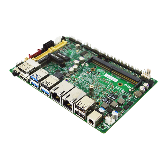
Page 8: Layout Diagram
1* CPU FAN connector 1* Front panel header 2* 9-pin USB 2.0 header (Expansible to 2* USB 2.0 ports) 6* Serial port header (COM1 supports RS232/422/485; COM2/3/4/5/6 supports RS232) 1* SIM card slot (co-function with M.2 B-key, 3042 slot) ... - Page 9 Diagram-Front Side: BATCON SMBUS SATAIII SATA Power Out Front Panel Port Connector INVERTER Audio Header USB 2.0 Port Header Line-out/MIC Port LVDS Header USB 2.0 Port Header M.2 E-key Slot (M2E) HDMI Port M.2 B-key Slot Front Panel (M2B) M.2 M-key Slot Header (M2M) (JW_FP)
- Page 10 Diagram-Back Side: SIM Card Slot *Note: SIM card slot (along with M.2 B-key)
- Page 11 Jumper Positions: AT_MODE M2M_PWR JPBKLT JPLCD M2B_PWR JP80P M2E_PWR JPCOM1 JPCOM2 JPCLR...
- Page 12 Jumpers Jumper Name Description Pitch JPCOM1/JPCOM2 COM1/COM2 Header Pin-9 4-Pin Block 2.0mm Function Select JP80P Set GPIO_CON 2-Pin Block 2.0mm JPLCD LCD Panel VCC Power Select 4-Pin Block 2.0mm JPBKLT LCD Backlight Power VCC Select 4-Pin Block 2.0mm M2B_PWR M.2 B-key Power Select 3-Pin Block 2.0mm M2E_PWR...
- Page 13 SATA1 SATAIII Port Connector SATAPWR SATA HDD Power-out Connector CPUFAN CPU FAN Connector Headers Header Name Description Pitch JW_FP Front Panel Header 8-pin Block 2.0mm (PWR LED/ HDD LED/Power Button /Reset) FP_USB1/ USB 2.0 Port Header X2 9-pin Block 2.0mm FP_USB2 FP_AUDIO Front Panel Audio Header...
-
Page 14: Chapter 2 Hardware Installation
Chapter 2 Hardware Installation 2-1 Jumper Settings JPCOM1/JPCOM2 (4-pin): COM1/COM2 Header Pin-9 Function Select (2.0 pitch) JPCOM1 JPCOM2 JP80P (2-pin): Set GPIO_CON (2.0 pitch) 1-2 Open: GPIO_CON=80 Port JP80P 1-2 Closed: GPIO_CON=GPIO Port (Default) - Page 15 JPLCD (4-pin): LCD Panel VCC Power Select (2.0 pitch) JPLCD JPBKLT (4-pin): LCD Backlight Power VCC Select (2.0 pitch) JPBKLT 4-6 Closed: 2-4 Closed: 3-4 Closed: Backlight Power Backlight Power Backlight Power =Adapter VCC =VCC; =12V; (12~24V) *Note: In the case that JPBKLT is set as Pin(4-6) closed, backlight power VCC is the same as adapter voltage value (wide voltage range from 12V to 24V).
- Page 16 M2B_PWR (3-pin): M.2 B-key Power Select (2.0 pitch) M2B_PWR 2-3 Closed: 1-2 Closed: VCC= 3VSB VCC= VCC3 M2E_PWR (3-pin): M.2 E-key Power Select (2.0 pitch) M2E_PWR 1-2 Closed: 2-3 Closed: VCC= VCC3 VCC= 3VSB...
- Page 17 M2M_PWR(3-pin): M.2 M-key Power Select (2.0 pitch) M2M_PWR 1-2 Closed: 2-3 Closed: VCC= 3VSB VCC= VCC3 PIN(1-2) of JPCLR (8-pin): Clear RTC (2.0 pitch) Pin1 1-2 Open: Normal(Default) Pin1 JPCLR 1-2 Closed: Clear RTC...
- Page 18 PIN(3-4) of JPCLR (8-pin): Clear CMOS (2.0 pitch) JPCLR *Note: Due to Intel MRC Code design factor, the first reboot after Clear CMOS will run a full Memory Sizing, and the boot time will take about 40 seconds (normal reboot time length, not function failure). PIN(5-6) of JPCLR (8-pin): ME Disable (2.0 pitch) PIN(5-6): ME Disable...
- Page 19 PIN(7-8) of JPCLR (8-pin): CASE OPEN (2.0 pitch) JPCLR Pin (7-8) Closed: When Case open function pin short to GND, the Case open function was detected. When used, needs to enter BIOS and enable ‘Case Open Detect’ function. In this case if your case is removed, next time when you restart your computer, a message will be displayed on screen to inform you of this.
-
Page 20: Connectors And Headers
Connectors and Headers 2-2-1 Connectors (1) Rear I/O Connectors * Refer to Page-3 Rear IO Diagram. Icon Name Function For user to connect compatible power 12~24V DC-in adapter to provide power supply for the Power Jack system. To connect USB keyboard, mouse or other devices compatible with USB 3.1(Gen.2) USB 3.1(Gen.2) Port specification. - Page 21 (2) DCIN (2-pin) : Internal 12~24V DC-in Power Connector DCIN Warning: Find Pin-1 position before connecting power cable to this 2-pin power connector. WRONG INSTALLATION DIRECTION WILL DAMAGE THE BOARD!! (3) SATA1 (7-pin): SATAIII Port connector This is a high-speed SATAIII port that supports 6GB/s transfer rate. SATA1...
- Page 22 (4) SATAPWR (4-pin): SATA HDD Power-Out Connector SATAPWR Warning: Make sure that Pin-1 of compatible SATA Power out connector is inserted into corresponding Pin-1 of SATAPWR connector to avoid possible damage to the board and hard disk driver! (5) CPUFAN (4-pin): CPU FAN Connector Control Fan Speed +12V Fan Power...
-
Page 23: Headers
2-2-2 Headers JW_FP (8-pin): Front Panel Header (2.54 pitch) JW_FP FP_USB1/FP_USB2 (9-pin): USB 2.0 Port Header (2.0 pitch) FP_USB1 FP_USB2 +DATA +DATA -DATA -DATA Pin 1... - Page 24 FP_AUDIO (9-pin): Front Panel Audio Header (2.0 pitch) This header connects to Front Panel Line-out, MIC-In connector with cable. FP_AUDIO GPIO_CON (10-pin): GPIO Port Header (2.0 pitch) GPIO86 GPIO87 GPIO84 GPIO85 GPIO83 GPIO82 GPIO81 GPIO80 GPIO_CON...
- Page 25 COM1/COM2/COM3/COM4/COM5/COM6 (9-pin): Serial Port Headers (2.0 pitch) COM1: RS232/422/485 Serial Port Header. COM2/COM3/COM4/COM5/COM6: RS232 Serial Port Header. COM1 COM2 Pin NO. RS232 *RS422 *RS485 (COM1) (COM1) Pin 1 DATA- COM3 Pin 2 DATA+ COM4 Pin 3 Pin 4 COM5 Pin 5 Pin 6 DSR- COM6...
- Page 26 eDP (40-pin): 4-lane eDP Port Header (1.25 pitch) Pin40 Pin21 Pin1 Pin20 Pin Define Pin Define BKLT_PWR Pin 40 Pin 20 LCD_VCC BKLT_PWR Pin 39 Pin 19 LCD_VCC BKLT_PWR Pin 38 Pin 18 LCD_VCC BKLT_PWR Pin 37 Pin 17 BKLT_PWR Pin 36 Pin 16 EDP_AUXN_C EDP_SCL...
- Page 27 LVDS (30-pin): 24-bit Dual Channel LVDS Port Header (1.25 pitch) LVDS Pin2 Pin1 Pin Define Pin NO. Pin NO. Pin Define LCD_VCC Pin 30 Pin 29 LCD_VCC LCD_VCC Pin 28 Pin 27 LCD_VCC LVDSA_DATAN0 Pin 26 Pin 25 LVDSA_DATAP0 LVDSA_DATAN1 Pin 24 Pin 23 LVDSA_DATAP1...
- Page 28 INVERTER (8-pin): LVDS Inverter Connector (2.0 pitch) INVERTER Pin No. Definition Pin1 LCD_BKLT_EN LCD_BKLT_PWM Backlight VCC Backlight VCC BRTNSS_UP BRTNSS_DOWN Warning! Find Pin-1 location of the inverter and make sure that the installation direction is correct! Otherwise serious harm will occur to the board/display panel!! SMBUS (5-pin): SM BUS Header (2.0 pitch) SMBUS...
-
Page 29: Chapter 3 Introducing Bios
Chapter 3 Introducing BIOS Notice! The BIOS options in this manual are for reference only. Different configurations may lead to difference in BIOS screen and BIOS screens in manuals are usually the first BIOS version when the board is released and may be different from your purchased motherboard. Users are welcome to download the latest BIOS version form our official website. -
Page 30: Bios Menu Screen
BIOS Boot Menu Screen (boot device options please refer to actual configuration) 3-2 BIOS Menu Screen The following diagram show a general BIOS menu screen: Menu Bar General Help Items Current Setting Value Menu Items Function Keys... -
Page 31: Function Keys
3-3 Function Keys In the above BIOS Setup main menu of, you can see several options. We will explain these options step by step in the following pages of this chapter, but let us first see a short description of the function keys you may use here: ... -
Page 32: Memu Bars
3-5 Menu Bars There are six menu bars on top of BIOS screen: Main To change system basic configuration Advanced To change system advanced configuration Chipset To change chipset configuration Security Password settings Boot To change boot settings Save & Exit Save setting, loading and exit options. -
Page 33: Advanced Menu
System Language Choose the system default language. System Date Set the date. Please use [Tab] to switch between date elements. System Time Set the time. Please use [Tab] to switch between time elements. 3-7 Advanced Menu CPU Configuration Press [Enter] to view current CPU configuration and make settings for the following sub-items:... - Page 34 Boot Performance Mode Use this item to select the performance state that the BIOS will set starting from reset vector. The optional settings: [Max Battery]; [Max Non-Turbo Performance]; [Turbo Performance] Intel(R) SpeedStep(tm) This item allows more than two frequency ranges to be supported. The optional settings: [Disabled];...
- Page 35 window. The optional settings: [Disabled]; [Enabled]. When set as [Enabled], the following sub-items shall appear: Power Limit1 Power Limit1 in Milli Watts. BIOS will round to the nearest 1/8W when programming. 0= no custom override. For 12.50W, enter 12500. Overclocking SKU:Value must be between Max and min Power Limits (specified by PACKAGE_POWER_SKU_MSR).
- Page 36 list of settings and their current state are displayed below when Intel® TCC mode is enabled. The optional settings: [Disabled]; [Enabled]. Intel® TCC Authentication Use this item to enable or disable Authentication of Intel® TCC configuration date. The optional settings: [Disabled]; [Enabled]. When Intel®...
- Page 37 The optional settings: [Disabled]; [Enabled]. SHA256 PCR Bank Use this item to enable or disable SHA256 PCR Bank. The optional settings: [Disabled]; [Enabled]. SHA384 PCR Bank Use this item to enable or disable SHA384 PCR Bank. The optional settings: [Disabled]; [Enabled]. When PTT configuration >...
- Page 38 When set as [Enabled], user can make further settings in the following items: Device Settings Change Settings Use this item to select an optimal setting for Super IO Device. The optional settings: [Auto]; [IO=3F8h; IRQ=4;]; [IO=2F8h; IRQ=3;]; [IO=3E8h; IRQ=4;]; [IO=2E8h; IRQ=3;]. Transmission Mode Select The optional settings: [RS422];...
- Page 39 Change Settings Use this item to select an optimal setting for Super IO Device. The optional settings: [Auto]; [IO=3F8h; IRQ=10;]; [IO=2F8h; IRQ=10;]; [IO=3E8h; IRQ=10;]; [IO=2E8h; IRQ=10;]; [IO=2F0h; IRQ=10;]; [IO=2E0h; IRQ=10;]; ► Serial Port 5/ Serial Port 6 Configuration Press [Enter] to make settings for the following items: Serial Port Use this item to enable or disable Serial Port (COM).
- Page 40 Reset Timer Unit’ set as [Sec]; or in the range of [1] to [255] minutes when ‘WatchDog Reset Timer Unit’ set as [Min]. WatchDog Reset Timer Unit The optional settings: [Sec.]; [Min.]. WatchDog Wake-up Timer Use this item to enable or disable WDT wake-up function. The optional settings: [Disabled];...
- Page 41 Console Redirection Settings Terminal Type The optional settings: [VT100]; [VT100+]; [VT-UTF8]; [ANSI]. Emulation: [ANSI]: Extended ASCII char set; [VT100]: ASCII char set; [VT100+]: Extends VT100 to support color, function keys, etc.; [VT-UTF8]: Uses UTF8 encoding to map Unicode chars onto 1 or more bytes. Bits per second Use this item to select serial port transmission speed.
- Page 42 The optional settings: [None]; [Hardware RTS/CTS]. VT-UTF8 Combo Key Support Use this item to enable VT-UTF8 Combination Key Support for ANSI/VT100 terminals. The optional settings: [Disabled]; [Enabled]. Recorder Mode With this mode enable only text will be sent. This is to capture Terminal data. The optional settings: [Disabled];...
- Page 43 best choice is [VT100+] and them [VT100]. See above, in Console Redirection Settings page, for more help with Terminal Type/Emulation. Bits per second EMS Use this item to select serial port transmission speed. The speed must be matched on the other side. Long or noisy lines may require lower speeds. The optional settings: [9600];...
- Page 44 Use this item to set CPUFAN full speed temperature. Fan will run at full speed when above this pre-set temperature. CPUFAN Full-Speed Duty Use this item to set CPUFAN full-speed duty. Fan will run at full speed when above this pre-set duty. CPUFAN Idle-Speed Temperature Use this item to set CPUFAN idle speed temperature.
- Page 45 itself to the host controller. ‘Auto’ uses default value: for a root port it is 100 ms, for a hub port the delay is taken from hub descriptor. The optional settings: [Auto]; [Manual]. Select [Manual] you can set value for the following sub-item: ‘Device power-up delay in seconds’, the delay range in from 1 to 40 seconds, in one second increments.
- Page 46 Wake-up Function Settings Press [Enter] to make settings for the following sub-items: Wake-up System With Fixed Time Use this item to enable or disable System wake on alarm event. The optional settings: [Disabled]; [Enabled]. When set as [Enabled], the following items shall appear: Wake-up Hour Use this item to select 0-23.
-
Page 47: Chipset Menu
Use this item to selects TPM device. The optional settings: [dTPM]; [PTT]. [PTT]: Enables PTT in SkuMgr; [dTPM]: Disable PTT in SkuMgr. Warning! PTT/dTPM will be disabled and all data saved on it will be lost. Intel(R) Ethernet Controller I225-V-XX:XX:XX:XX:XX:XX ... - Page 48 System Agent (SA) Configuration GTT Size Use this item to select the GTT Size. The optional settings: [2MB]; [4MB]; [8MB]. DVMT Pre-Allocated Use this item to select DVMT 5.0 Pre-Allocated (Fixed) Graphics Memory size used by the Internal Graphics Device. The optional settings: [0M];...
- Page 49 PCI Express Configuration Peer Memory Write Enable Use this item to enable or disable peer memory write. The optional settings: [Disabled]; [Enabled]. SATA Configuration SATA Controller Use this item to enable or disable SATA device. The optional settings: [Disabled]; [Enabled]. When set as [Enabled], the following sub-items shall appear: SATA Mode Selection This item determines how SATA controller(s) operate.
-
Page 50: Security Menu
PinCntrl Driver GPIO Scheme Use this item to enable/disable PinCntrl Driver GPIO Scheme The optional settings: [Disabled]; [Enabled]. 3-9 Security Menu Security menu allow users to change administrator password and user password settings. Administrator Password If there is no password present on system, please press [Enter] to create new administrator password. - Page 51 User Password If there is no password present on system, please press [Enter] to create new administrator password. If password is present on system, please press [Enter] to verify old password then to clear/change password. Press again to confirm the new administrator password.
- Page 52 authentication, which includes the following items: Vendor Keys Factory Key Provision This item is for user to install factory default Secure Boot keys after the platform reset and while the System is in Setup mode. The optional settings: [Disabled]; [Enabled]. ...
-
Page 53: Boot Menu
a) EFI_SIGNATURE_LIST b) EFI_ CERT_X509 (DER) c) EFI_ CERT_RSA2048 (bin) d) EFI_ CERT_SHAXXX 2. Authenticated UEFI Variable 3. EFI PE/COFF Image (SHA256) Key Source: Factory, External, Mixed. 3-10 Boot Menu Boot Configuration Setup Prompt Timeout Use this item to set number of seconds to wait for setup activation key. 65535... - Page 54 (0xFFFF) means indefinite waiting. Bootup NumLock State Use this item to select keyboard NumLock state. The optional settings: [On]; [Off]. Quiet Boot Use this item to enables or disable Quiet Boot option. The optional settings: [Disabled]; [Enabled]. Boot Option Priorities Use this item to set the system boot order.
-
Page 55: Save & Exit Menu
3-11 Save & Exit Menu Save Changes and Reset This item allows user to reset the system after saving the changes. Discard Changes and Reset This item allows user to reset the system without saving any changes. Restore Defaults Use this item to restore /load default values for all the setup options. Save as User Defaults Use this item to save the changes done so far as user defaults.
Need help?
Do you have a question about the MF20 Series and is the answer not in the manual?
Questions and answers