Table of Contents
Advertisement
Quick Links
USER'S MANUAL
Of
NVIDIA MCP78S
Based
Mini-ITX M/B For AMD Socket AM2+ Processor
NO.G03-NC62-F
Rev1.0
Release date: May, 2008
Trademark:
* Specifications and Information contained in this documentation are furnished for information use only, and are
subject to change at any time without notice, and should not be construed as a commitment by manufacturer.
Advertisement
Table of Contents

Related Manuals for JETWAY MCP78S


Summary of Contents for JETWAY MCP78S
- Page 1 USER'S MANUAL NVIDIA MCP78S Based Mini-ITX M/B For AMD Socket AM2+ Processor NO.G03-NC62-F Rev1.0 Release date: May, 2008 Trademark: * Specifications and Information contained in this documentation are furnished for information use only, and are subject to change at any time without notice, and should not be construed as a commitment by manufacturer.
- Page 2 Environmental Protection Announcement Do not dispose this electronic device into the trash while discarding. To minimize pollution and ensure environment protection of mother earth, please recycle.
-
Page 3: Table Of Contents
TABLE OF CONTENT USER’S NOTICE ..........................iii MANUAL REVISION INFORMATION .................... iii ITEM CHECKLIST..........................iii CHAPTER 1 INTRODUCTION OF AMDCS5536 CHIPSET MOTHERBOARD FEATURE OF MOTHERBOARD..................1 1-1-1 SPECICAL FEATURE OF MOTHERBOARD............. 2 SPECIFICATION........................3 LAYOUT DIAGRAM & JUMPER SETTING ..............5 CHAPTER 2 HARDWARE INSTALLATION HARDWARE INSTALLATION STEPS................ -
Page 4: User's Notice
USER’S NOTICE COPYRIGHT OF THIS MANUAL BELONGS TO THE MANUFACTURER. NO PART OF THIS MANUAL, INCLUDING THE PRODUCTS AND SOFTWARE DESCRIBED IN IT MAY BE REPRODUCED, TRANSMITTED OR TRANSLATED INTO ANY LANGUAGE IN ANY FORM OR BY ANY MEANS WITHOUT WRITTEN PERMISSION OF THE MANUFACTURER. -
Page 5: Feature Of Motherboard
The motherboard series are designed for the new generation AMD processor family guaranteed both of the performance and stability of general purpose IPC and dedicated IPC platform solutions. The MCP78S chipset is fully optimized to provide the variety IPC platform solutions by featuring the high compatibilities and cost-effective, low power consumption, high performance, and superior core graphics engine. -
Page 6: Specical Feature Of Motherboard
hardware monitor function on system to monitor and protect your system and maintain your non-stop business computing. Targets at High Growth Markets: Digital Home / Digital Office / Digital World - Personal electronics such as personal video recorders (PVR), set top boxes, home theatres, digital audio centers, etc. -
Page 7: Specification
Specification Spec Description ∗ Mini ITX form factor 6 layers PCB size: 17.0x17.0cm Design ∗ NVIDIA MCP78S single chipset Chipset ∗ Support HT3.0 Embedded CPU ∗ Low Power Consumption ∗ Socket AM2+ / AM2 AMD CPU ∗ 240-pin DDRII DIMM socket x1 ∗... -
Page 8: Layout Diagram & Jumper Setting
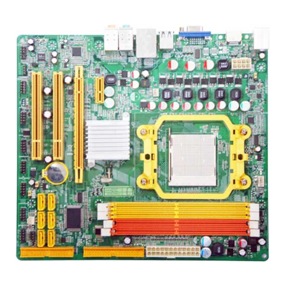
∗ Award 8MB SPI Flash ROM BIOS ∗ PS/2 keyboard&Mouse Connector ∗ D-Sub 15-pin VGA Conn. ∗ USB 2.0 connector x6, USB2.0 header x2 ∗ Serial port D-Sub x2 Multi I/O ∗ 8-channel Audio connector (Line-out, MIC and SPDIF in/out ) ∗... - Page 9 ATX Power Connector Clear CMOS Rs232 Power Sel 2 VGA and DVI 240pin DDRII Connector DIMM Socket Audio Connector SYS FAN2 MCP78S Chipset ATA133 IDE Connector USB Port Connector (optional) SYS FAN1 Front Panel SATAII (1,2,3,4) CD IN Connector Connector Speak Connector...
- Page 10 ALC 883 AUDIO CODEC 8MB Flash SPI ROM BIOS 8111C PCI-E LAN 8211B PHY(optional)
-
Page 11: Expansion Sockets
Jumper Jumper Name Description Page JBAT CMOS RAM Clear Function Setting 3-pin Block Connectors Connector Name Description Page 12V CN 4-Pin 12V Power Connector 4-pin Block p.12 USB1,USB2 USB Port Connector 4-pin Connector p.13 UL3,UL4 RJ45 LAN Connector 4-pin Connector p.14 VGA CN VGA Port Connector... -
Page 12: Chapter 2 Hardware Installation
Chapter 2 Hardware installation Hardware installation Steps Before using your computer, you had better complete the following steps: 1. Check motherboard jumper setting 2. Install System Memory (DIMM) 3. Install Expansion cards 4. Connect IDE, Front Panel /Back Panel cable 5. -
Page 13: Install Memory
2-3 closed Clear CMOS 1-2 closed Normal (Default) CMOS RAM Clear Setting Install Memory The motherboards provide one 240-pin DDRII MEMORY MODULE sites for memory expansion available from minimum memory size of 64MB to maximum memory size of 2.0GB DDRII SDRAM. Valid Memory Configurations Bank 240-Pin DIMM... - Page 14 Generally, installing DDRII memory to your motherboard is very easy; you can refer to figure 2-4 to see what a 240-Pin DDR 800II / DDRII 667 DDR SDRAM module looks like. DIMM0 & DIMM1 DIMM0 & DIMM1 NOTE! When you install DIMM module fully into the DIMM socket the eject tab should be locked into the DIMM module very firmly and fit into its indention on both sides.
-
Page 15: Expansion Cards
Expansion Cards WARNING! Turn off your power when adding or removing expansion cards or other system components. Failure to do so may cause severe damage to both your motherboard and expansion cards. 2-4-1 Procedure For Expansion Card Installation 1. Read the documentation for your expansion card and make any necessary hardware or software setting for your expansion card such as jumpers. -
Page 16: Connectors And Headers
Connectors and Headers 2-5-1 Connectors (1) 12V Power Connector (4-pin block):12V CN This is a newly defined 4-pins connector support extra 12V voltage to maintain system power consumption in the case that an AD-Scalar daughter board is used. Without this connector might cause system unstable because the power supply can not provide sufficient current for system. - Page 17 DVI Connector (24-pin female): DVI DVI Connector is a 24-pin D-Subminiature Receptacle connector. This interface standard designed to maximize the visual quality of digital display devices such as flat panel LCD computer displays and digital projectors. (6) Audio Connector (Line-Out/ MIC): This Connector is 2 phone Jack for LINE-OUT/ MIC.
-
Page 18: Headers
2-5-2 Headers (1) USB Port Headers (9-pin): USB1,USB2 These headers are used for connecting the additional USB port plug. By attaching an option USB cable, your can be provided with two additional USB plugs affixed to the back panel. USB1 USB2 Pin 1 Pin 1... - Page 19 IDE1 Pin 1 (3) Power switch: PWR BTN This 2-pin connector connects to the case-mounted power switch to power ON/OFF the system. JW FP Power Reset button button Power LED HD-LED button button System Case Connections...
-
Page 20: Starting Up Your Computer
(4) Serial ATA Connector (7-pin female): SATAII1/SATAII2/SATAII3/SATAII4 This connector supports the provided Serial ATA2 IDE hard disk cable to connecting the motherboard and serial ATAII hard disk. SATA1 SATA2 SATA3 SATA4 Serial-ATA2 Port Connector Starting Up Your Computer 1. After all connections are made, close your computer case cover. 2. - Page 21 5. The power LED on the front panel of the system case will light. The LED on the monitor may light up or switch between orange and green after the system is on. If it complies with green standards or if it is has a power standby feature. The system will then run power-on test.
Need help?
Do you have a question about the MCP78S and is the answer not in the manual?
Questions and answers