Table of Contents
Advertisement
Quick Links
TECHNICAL MANUAL
of
Intel Q470E Express Chipset
Based Mini-ITX M/B
NO. G03-MI92-F
Revision: 1.0
Release date: November 30, 2020
Trademark:
* Specifications and Information contained in this documentation are furnished for information use only, and are
subject to change at any time without notice, and should not be construed as a commitment by manufacturer.
Advertisement
Table of Contents

Related Manuals for JETWAY MI92


Summary of Contents for JETWAY MI92
- Page 1 TECHNICAL MANUAL Intel Q470E Express Chipset Based Mini-ITX M/B NO. G03-MI92-F Revision: 1.0 Release date: November 30, 2020 Trademark: * Specifications and Information contained in this documentation are furnished for information use only, and are subject to change at any time without notice, and should not be construed as a commitment by manufacturer.
- Page 2 Environmental Protection Announcement Do not dispose this electronic device into the trash while discarding. To minimize pollution and ensure environment protection of mother earth, please recycle.
-
Page 3: Table Of Contents
TABLE OF CONTENT ENVIRONMENTAL SAFETY INSTRUCTION................iii USER’S NOTICE..........................iv MANUAL REVISION INFORMATION...................iv ITEM CHECKLIST..........................iv CHAPTER 1 INTRODUCTION OF THE MOTHERBOARD FEATURE OF MOTHERBOARD..................1 SPECIFICATION........................2 LAYOUT DIAGRAM.......................3 CHAPTER 2 HARDWARE INSTALLATION JUMPER SETTING........................ 7 CONNECTORS AND HEADERS..................11 2-2-1 CONNECTORS......................11 2-2-2 HEADERS........................ -
Page 4: Environmental Safety Instruction
Environmental Safety Instruction Avoid the dusty, humidity and temperature extremes. Do not place the product in any area where it may become wet. 0 to 40 centigrade is the suitable temperature. (The temperature comes from the request of the chassis and thermal solution) ... -
Page 5: User's Notice
USER’S NOTICE COPYRIGHT OF THIS MANUAL BELONGS TO THE MANUFACTURER. NO PART OF THIS MANUAL, INCLUDING THE PRODUCTS AND SOFTWARE DESCRIBED IN IT MAY BE REPRODUCED, TRANSMITTED OR TRANSLATED INTO ANY LANGUAGE IN ANY FORM OR BY ANY MEANS WITHOUT WRITTEN PERMISSION OF THE MANUFACTURER. -
Page 6: Chapter 1 Introduction Of The Motherboard
Chapter 1 Introduction of the Motherboard 1-1 Feature of Motherboard Intel ® Q470E express chipset LGA 1200 CPU socket for the 10 Intel Core i7/ i5 /i3, Celeron & Pentium ® ™ ® processors (TDP Max support 65W) ... -
Page 7: Specification
1-2 Specification Spec Description Design Mini-ITX form factor; PCB size:17.0x17.0cm Chipset Intel Q470E Express Chipset Intel LGA 1200 Socket supports 10 Core i7/i5/i3/Pentium/Celeron processors (Max. 65W TDP) CPU Socket * Note: for detailed CPU support information please visit our website ... -
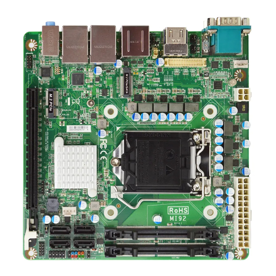
Page 8: Layout Diagram
2* USB 3.2 (Gen.1) 5Gbps port 2* RJ-45 LAN port 1* 3-jack audio connector (Line-in, Line-out, MIC) Internal I/O Connectors & Headers: 1* 24-pin main power connector 1* 4-pin 12V power connector 1* CPUFAN connector & 1* SYSFAN connector ... - Page 9 Motherboard Internal Diagram SYSFAN1 Connector ATX Type Main Power Connector ATX 12V Power Connector LGA 1200 CPU Socket EDP Port Header DDR4 SODIMM Slots (SODIMM1/SODIMM2) PS/2 Keyboard & Mouse Header *Rear IO Connector (Refer to Page-3) Intel Q470E Chipset CPUFAN1 M.2 M-Key Slot Connector (M2M)
- Page 10 Motherboard Jumper Positions JP13 JP12 COPEN JAT_ATX JBAT...
- Page 11 Jumper Name Description Pitch JP12 COM1 Port Pin9 Function Select 4-pin Block 2.0mm JP13 COM2 Port Pin9 Function Select 4-pin Block 2.0mm JBAT Clear CMOS RAM Settings 3-pin Block 2.0mm Flash Descriptor Override 2-pin Block 2.0mm JAT_ ATX ATX Mode / AT Mode Select 3-pin Block 2.0mm COPEN...
-
Page 12: Chapter 2 Hardware Installation
SMBUS SMBUS Header 5-pin Block 2.0mm FP_AUDIO Front Panel Audio Header 9-pin Block 2.0mm PS2KBMS1 PS2 Keyboard & Mouse Header 6-pin Block 2.54mm EDP Header 40-pin Block 1.25mm Chapter 2 Hardware Installation 2-1 Jumper Setting JP12 (4-pin): COM1 Port Pin9 Function Select JP12 *Note:Maximum current limit is 500mA while using 5V or 12V. - Page 13 JP13 (4-pin): COM2 Port Pin9 Function Select JP13 *Note:Maximum current limit is 500mA while using 5V or 12V. JBAT (3-pin): Clear CMOS RAM Settings JBAT...
- Page 14 JP2(2-pin): Flash Descriptor Override Select → Flash Descriptor Override Pin1 1-2 Open: Enable Security Measures in the Flash Descriptor(Default); Pin1 1-2 Closed: Disable Flash Descriptor Security (override). JAT_ATX (3-pin): ATX Mode/AT Mode Select JAT_ATX *ATX Mode Selected: Press power button to power on after power input ready; AT Mode Selected: Directly power on as power input ready.
- Page 15 COPEN (2-pin): Case Open Message Display Function Select COPEN → Case Open Detection Override COPEN Pin1 Pin (1&2) Closed: When Case open function pin short to GND, the Case open function was detected. When used, needs to enter BIOS and enable ‘Case Open Detect’...
-
Page 16: Connectors And Headers
Connectors and Headers 2-2-1 Connectors Rear Panel Connectors *Refer to Page-3 Rear IO Diagram Icon Name Function Mainly for user to connect external MODEM or other RS232/422/485 devices that supports Serial Port Serial Communications Interface. To connect display device that support HDMI HDMI Port specification. - Page 17 (1) COM1-2: RS232/422/485 Ports COM1/COM2 port can function as RS232/422/485 port. In normal settings COM1/COM2 functions as RS232 port. With compatible COM cable COM1/COM2 can function as RS422 or RS 485 port. User also needs to go to BIOS to set ‘Transmission Mode Select’...
- Page 18 (2) ATXPWR(24-pin block): Main Power Connector Row2 Row1 Pin12 Pin1 PIN ROW1 ROW2 +3.3V +3.3V +3.3V -12V Soft Power on Power OK +5V Stand by +5V +12V +12V +3.3V (3) ATX12V (4-pin block): ATX-Type 12V Power Connector Pin1 Pin No. Definition +12V +12V...
- Page 19 (4) SATA1/2/3/4 (7-pin): SATAIII Port connector These are high-speed SATAIII port that supports 6GB/s transfer rate. SATA2 Pin No. Definition SATA1 SATA4 SATA4 (5) CPUFAN1 (4-pin): CPU Fan Connector CPUFAN1 Control Fan Speed +12V Fan Power Pin1 *Note: Maximum current limit is 1.5A while using 12V working voltage.
-
Page 20: Headers
(6) SYSFAN1(4-pin): System Fan Connector SYSFAN1 Control Fan Speed +12V Fan Power Pin1 *Note: Maximum current limit is 1.5A while using 12V working voltage. 2-2-2 Headers (1) FP (9-pin): Front Panel Header Pin1 PWRLED+ HDDLED+ HDDLED- PWRLED- PWRBTN RSTSW VCC5V *Note: Maximum current limit is 1A while using 5V working voltage. - Page 21 (2) GPIO (10-pin): GPIO Port Header Pin1 SIO_GPIO66 SIO_GPIO71 SIO_GPIO72 SIO_GPIO73 SIO_GPIO74 SIO_GPIO75 GPIO SIO_GPIO76 SIO_GPIO77 VCC5V *Note: Maximum current limit is 1A while using 5V working voltage. (3) FP_USB1 (9-pin): USB 2.0 Port Header Pin1 FP_USB1 *Note: Maximum current limit is 1.5A in total while using 5V work ing voltage.
- Page 22 (4) SMBUS (5-pin): SMBUS Header SMBUS (5) FP_AUDIO (9-pin): Line-Out, MIC-In Header This header connects to Front Panel Line-out, MIC-In connector with cable. FP_AUDIO...
- Page 23 (6) PS2KBMS1 (6-pin): PS/2 Keyboard & Mouse Header PS2KBMS1 *Note: Maximum current limit is 500mA while using 12V working voltage.
- Page 24 (7) EDP (40-Pin): EDP wafer Pin40 Pin20 Pin21 Pin1 Pin Define Pin NO. Pin NO. Pin Define Pin 40 Pin 20 LCD_VCC Backlight power Pin 39 Pin 19 LCD_VCC Backlight power Pin 38 Pin 18 LCD_VCC Backlight power Pin 37 Pin 17 Backlight power Pin 36...
-
Page 25: Chapter 3 Introducing Bios
Chapter 3 Introducing BIOS Notice! The BIOS options in this manual are for reference only. Different configurations may lead to difference in BIOS screen and BIOS screens in manuals are usually the first BIOS version when the board is released and may be different from your purchased motherboard. Users are welcome to download the latest BIOS version form our official website. -
Page 26: Bios Menu Screen
BIOS Boot Menu Screen (boot device options please refer to actual configuration) 3-2 BIOS Menu Screen The following diagram show a general BIOS menu screen: Menu Bar General Help Items Current Setting Value Menu Items Function Keys... -
Page 27: Function Keys
3-3 Function Keys In the above BIOS Setup main menu of, you can see several options. We will explain these options step by step in the following pages of this chapter, but let us first see a short description of the function keys you may use here: ... -
Page 28: Menu Bars
3-5 Menu Bars There are six menu bars on top of BIOS screen: Main To change system basic configuration Advanced To change system advanced configuration Chipset To change chipset configuration Security Password settings Boot To change boot settings Save & Exit Save setting, loading and exit options. -
Page 29: Main Menu
3-6 Main Menu Main menu screen includes some basic system information. Highlight the item and then use the <+> or <-> and numerical keyboard keys to select the value you want in each item. System Date Set the date. Please use [Tab] to switch between date elements. System Time Set the time. -
Page 30: Advanced Menu
3-7 Advanced Menu Connectivity Configuration Use this item to configure Connectivity related options. Press [Enter] to make settings for the following sub-items: CNVi present CNVi Configuration CNVi Mode This option configures Connectivity. The optional settings: [Disabled Integrated]; [Auto Detection]. [Auto Detection] means that if Discrete solution is discovered it will be enabled by default. - Page 31 Use this item to enable or disable Hyper-Threading Technology. The optional settings: [Disabled]; [Enabled]. Intel (VMX) Virtualization Technology The optional settings: [Disabled]; [Enabled]. When set as [Enabled], a VMM can utilize the additional hardware capabilities provided by Vanderpool Technology. Intel(R) SpeedStep(tm) This item allows more than two frequency ranges to be supported.
- Page 32 Use this item to designate this port as Hot Pluggable. The optional settings: [Disabled]; [Enabled]. Port Use this item to Enable or Disable SATA Port. The optional settings: [Disabled]; [Enabled]. PCH-FW Configuration Press [Enter] to view Management Engine Technology Parameters and make settings in the following sub-item: ME Firmware Version ME Firmware Mode...
- Page 33 Activate Remote Assistance Process Use this item to trigger CIRA boot. *Note: Network Access must be activated first from MEBx Setup. The optional settings: [Disabled]; [Enabled]. *When set as [Enabled], user can make further settings in ‘CIRA Timeout’. CIRA Timeout OEM defined timeout for MPS connection to be established.
- Page 34 [Simulated]: Performs SE flow without erasing SSD. [Real]: Erase SSD. Force Secure Erase This item is for user to force Secure Erase on next boot. The optional settings: [Disabled]; [Enabled]. OEM Flags Settings Use this item to configure OEM flags. Press [Enter] to make settings for in the following sub-items: Hide Unconfigure ME Confirmation Prompt Use this function to enable or disable Hide Unconfigure ME confirmation prompt...
- Page 35 TPM 2.0 Device Found *Note: TPM function is optional, MI92-12 model supports TPM2.0. Security Device Support Use this item to enable or disable BIOS support for security device. O.S. will not show Security Device. TCG EFI protocol and INT1A interface will not be available.
- Page 36 The optional settings: [Disabled]; [Enabled]. When set as [Enabled], the following items shall appear: Wake-up Hour Use this item to select 0-23. For example enter 3 for 3am and 15 for 3pm. Wake-up Minute Use this item to select 0-59. Wake-up Second Use this item to select 0-59.
- Page 37 as [Disabled] if you wish to have all active wake-up functions. The optional settings: [Disabled]; [Auto]. ► Serial Port 1 Configuration Press [Enter] to make settings for the following items: Serial Port 1 Configuration Serial Port Use this item to enable or disable Serial Port (COM). The optional settings: [Disabled];...
- Page 38 Device Settings Change Settings Use this item to select an optimal setting for Super IO Device. The optional settings: [IO=2F8h; IRQ=3;]; [IO=3F8h; IRQ=3,4,5,7,10,11;]; [IO=2F8h; IRQ=3,4,5,7,10,11;]; [IO=3E8h; IRQ=3,4,5,7,10,11;]; [IO=2E8h; IRQ=3,4,5,7,10,11;]. Transmission Mode Select The optional settings: [RS422]; [RS232]; [RS485]. Mode Speed Select Use this item to select RS232/RS422/RS485 Speed.
- Page 39 When set as [Enabled], system will detect if COPEN has been short or not (refer to Page-10 COPEN jumper setting for Case Open Detection); if Pin 1&2 of COPEN are short, system will show Case Open Message during POST. PC Health Status Press [Enter] to view current hardware health status, make further settings in ‘SmartFAN Configuration’...
- Page 40 The settings specify how the host computer and the remote computer (which the user is using) will exchange data. Both computers should have the same or compatible settings. Press [Enter] to make settings for the following sub-items. COM1 Console Redirection Settings Terminal Type The optional settings: [VT100];...
- Page 41 the receiving buffers are full, a “stop” signal can be sent to stop the data flow. Once the buffers are empty, a “start” signal can be sent to re-start the flow. Hardware flow control uses two wires to send start/stop signals. The optional settings: [None];...
- Page 42 When [Bootloader] is selected, then Legacy Console Redirection is disabled before booting to legacy OS. When [Always Enabled] is selected, then Legacy Console Redirection is enabled for legacy OS. Default setting for this option is set to [Always Enabled]. Serial Port for Out-of-Band Management/ Windows Emergency Management Services (EMS) Console Redirection EMS Use this item to enable or disable Console Redirection.
- Page 43 Data Bits EMS The default setting is: [8]. *This item may or may not show up, depending on different configuration. Parity EMS The default setting is: [None]. *This item may or may not show up, depending on different configuration. Stop Bits EMS The default setting is: [1].
- Page 44 The optional settings: [10 sec]; [20 sec]; [30 sec]; [40 sec]. Device power-up delay Use this item to set maximum time the device will take before it properly reports itself to the host controller. ‘Auto’ uses default value: for a root port it is 100 ms, for a hub port the delay is taken from hub descriptor.
- Page 45 CSM Support Use this item enable or disable CSM support. The optional settings: [Disabled]; [Enabled]. When set as [Enabled], the following sub-items shall appear: Option ROM execution Network This option controls the execution of Network OpROM. The optional settings: [Do not launch]; [UEFI]; [Legacy]. Storage This option controls the execution of UEFI and Legacy Storage OpROM.
-
Page 46: Chipset Menu
3-8 Chipset Menu System Agent (SA) Configuration Press [Enter] to make settings for the following sub-items: System Agent (SA) Configuration VT-d ► Memory Configuration Press [Enter] to view brief information for the working memory module. ► Graphics Configuration Press [Enter] to make further settings for Graphics Configuration. Graphics Configuration Primary Display Use this item to select which of IGFX/PEG Graphics device should be Primary... - Page 47 The optional settings: [Auto]; [IGFX]; [PEG]. Primary IGFX Boot Display Use this item to select the Video Device which will be activated during POST. This has no effect if external graphics present. eDP will be supported only on primary display. The optional setting: [VBIOS Default];...
- Page 48 PEG Port Configuration PEG Lane Select Use this item to select X16 or X8/X8. The optional settings: [X16]; [X8/X8]. When set as [X8/X8], the PCIE2 Slot (Bifurcation) items shall appear: PCIE2 Slot Enable Root Port Use this item to enable or disable the Root Port. Root Port will Always Enable if set x8 Bifurcation.
- Page 49 Press [Enter] to make settings for the following sub-items: PCH-IO Configuration HD Audio Use this item to control Detection of the HD-Audio device. The optional settings: [Disabled]; [Enabled]. [Disabled]: HDA will be unconditionally disabled. [Enabled]: HAD will be unconditionally enabled. Onboard Lan1 Controller Use this item to enable or disable corresponding onboard NIC device or controller.
-
Page 50: Security Menu
3-9 Security Menu Security menu allow users to change administrator password and user password settings. Administrator Password If there is no password present on system, please press [Enter] to create new administrator password. If password is present on system, please press [Enter] to verify old password then to clear/change password. - Page 51 Press [Enter] to make customized secure settings: System Mode Secure Boot Secure Boot feature is Active if Secure Boot is Enabled, Platform Key (PK) is enrolled and the System is in User mode. The mode change requires platform reset. The optional settings: [Disabled]; [Enabled]. Secure Boot Mode Set UEFI Secure Boot Mode to Standard mode or Custom mode.
- Page 52 Export Secure Boot variables Enroll Efi Image This item allows the image to run in Secure Boot mode. Enroll SHA256 Hash certificate of a PE image into Authorized Signature Database (db). Device Guard Ready Remove ‘UEFI CA’ from DB ...
-
Page 53: Boot Menu
3-10 Boot Menu Boot Configuration Setup Prompt Timeout Use this item to set number of seconds to wait for setup activation key. Bootup Numlock State Use this item to select keyboard numlock state. The optional settings are: [On]; [Off]. Quiet Boot The optional settings are: [Disabled];... -
Page 54: Save & Exit Menu
3-11 Save & Exit Menu Save Options Save Changes and Reset This item allows user to reset the system after saving the changes. Discard Changes and Reset This item allows user to reset the system without saving any changes. Default Options Restore Defaults Use this item to restore /load default values for all the setup options.
Need help?
Do you have a question about the MI92 and is the answer not in the manual?
Questions and answers