Table of Contents
Advertisement
Quick Links
MU03 Series
User's Manual
NO.: G03-MU03-F
Revision: 1.0
Release date: July 5, 2022
Trademark:
* Specifications and Information contained in this documentation are furnished for information use only, and are
subject to change at any time without notice, and should not be construed as a commitment by manufacturer.
Advertisement
Table of Contents

Subscribe to Our Youtube Channel
Related Manuals for JETWAY MU03 Series


Summary of Contents for JETWAY MU03 Series
- Page 1 MU03 Series User’s Manual NO.: G03-MU03-F Revision: 1.0 Release date: July 5, 2022 Trademark: * Specifications and Information contained in this documentation are furnished for information use only, and are subject to change at any time without notice, and should not be construed as a commitment by manufacturer.
- Page 2 Environmental Protection Announcement Do not dispose this electronic device into the trash while discarding. To minimize pollution and ensure environment protection of mother earth, please recycle.
-
Page 3: Table Of Contents
TABLE OF CONTENT ENVIRONMENTAL SAFETY INSTRUCTION................... iv USER’S NOTICE............................ v MANUAL REVISION INFORMATION....................v ITEM CHECKLIST..........................v CHAPTER 1 INTRODUCTION OF THE MOTHERBOARD FEATURE OF MOTHERBOARD..................1 SPECIFICATION........................2 LAYOUT DIAGRAM.......................3 CHAPTER 2 HARDWARE INSTALLATION JUMPER SETTING........................ 7 CONNECTORS,WAFERS AND HEADERS..............11 2-2-1 CONNECTORS &... -
Page 4: Environmental Safety Instruction
Environmental Safety Instruction Avoid the dusty, humidity and temperature extremes. Do not place the product in any area where it may become wet. 0 to 60 centigrade is the suitable temperature. (The figure comes from the request of the main chipset) ... -
Page 5: User's Notice
USER’S NOTICE COPYRIGHT OF THIS MANUAL BELONGS TO THE MANUFACTURER. NO PART OF THIS MANUAL, INCLUDING THE PRODUCTS AND SOFTWARE DESCRIBED IN IT MAY BE REPRODUCED, TRANSMITTED OR TRANSLATED INTO ANY LANGUAGE IN ANY FORM OR BY ANY MEANS WITHOUT WRITTEN PERMISSION OF THE MANUFACTURER. -
Page 6: Chapter 1 Introduction Of The Motherboard
Chapter 1 Introduction of the Motherboard 1-1 Feature of Motherboard Onboard Intel Elkhart Lake series SoC processor, with low power consumption ® never denies high performance Support 1* DDR4 3200MHz SO-DIMM, maximum capacity up to 16GB Onboard 2* i225V 2.5GbE LAN port ... -
Page 7: Specification
1-2 Specification Spec Description Design NUC form factor; PCB size: 10.1 cm x 10.1 cm Integrated with Intel Elkhart Lake series CPU (TDP 10W) ® Embedded CPU * Note: CPU model varies from different IPC options. Please consult your dealer for more information of onboard CPU.TDP varies depending on CPU. -
Page 8: Layout Diagram
1* JW_FPB1(Backside) power wafer 1* CPUFANB1 (Backside) fan wafer 1* SMBUS header 1* 9-Pin USB 2.0/1.1 header for 2* USB 2.0/1.1 ports * RS232/422/485 serial port header 1* GPIO header (default GPIO/selectable by jumper ) ... - Page 9 Internal Diagram-Front Side: SATA HDD Power-Out AT_MODE USB 2.0 Port Wafer SMBUS Header Header SATAIII Port M.2 E-Key Slot Type-C RJ-45 LAN Port M.2 M-Key Slot (M2E1) (M2M1) USB 3.1 (Gen.2) JBAT Ports GPIO Port HDMI Port Header Line_Out / MIC Combo Port COM1 JPCAS_80P...
- Page 10 Internal Diagram-Back Side: JW_FPB1 Wafer Intel CPU CPUFANB1 Wafer...
- Page 11 Connectors Connector Name DCIN1 12V DC–in System Power Jack DP1_HDMI2 Top: Display Port Connector Bottom: HDMI Connector Top: 2.5Gbps RJ-45 LAN Port Connector Bottom: USB 3.1 (Gen.2) Port Connector HDMI1 HDMI Connector LAN1 2.5Gbps RJ-45 LAN Port Connector USB31 Top: USB 2.0 Port Connector Bottom: USB 3.1 (Gen.2) Port Connector AUDIO1 Line-Out/MIC Combo Connector...
-
Page 12: Chapter 2 Hardware Installation
Jumper Jumper Name Description Pitch AT_MODE ATX Mode/ AT Mode Select 3-Pin Block 2.0mm Pin (1-2): Case Open Display Select JPCAS_80P 4-Pin Block 2.0mm Pin (3-4): GPIO/80 Port Function Select JPCOM1 COM1 Port Pin9 Function Select 4-Pin Block 2.0mm Pin (1-2): Clear RTC JBAT Pin (3-4): Clear CMOS 6-Pin Block... - Page 13 Pin 1&2 of JPCAS_80P (4-pin): Case Open Display Select (Pitch 2.0mm) JPCAS_80P Pin (1&2) short: When Case open function pin short to GND, the Case open function was detected. When used, needs to enter BIOS and enable ‘Case Open Detect’ function. In this case if your case is removed, next time when you restart your computer, a message will be displayed on screen to inform you of this.
- Page 14 JPCOM1 (4-pin): COM1 Port Pin9 Function Select (Pitch:2.0mm) JPCOM1 Pin 1&2 of JBAT (6-pin): Clear RTC (Pitch:2.0mm) JBAT...
- Page 15 Pin (3&4) of JBAT (6-pin): Clear CMOS RAM Settings (Pitch:2.0mm) JBAT Pin 5&6 of JBAT (6-pin): ME Disabled (Pitch:2.0mm) JBAT...
-
Page 16: Connectors,Wafers And Headers
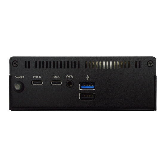
Connectors,Wafers and Headers 2-2-1 Connectors & Wafers Rear IO Panel Diagram: 2.5Gbps RJ-45 LAN Ports Display Port 12V DC-in Power Jack HDMI Port HDMI Port USB 3.1 (Gen.2) Port Front IO Panel Diagram: Type-C USB 2.0 Port USB 3.1 (Gen.2) Ports Power On/Off Button USB 3.1 (Gen.2) Port... - Page 17 Icon Name Function 12V DC–in system power connector For user to connect compatible power adapter to Power Connector provide power supply for the system. This connector is standard RJ-45 LAN jack for RJ-45 LAN Port Network connection. To connect USB keyboard, mouse or other devices USB 3.1(Gen.2) Port compatible with USB 3.1(Gen.2) specification.
- Page 18 SATA1 (7-pin Block): SATAIII Port connector The board comes with a SATAIII port that supports 6GB/s transfer rate. Pin No. Definition SATAPWR (4-pin): SATA HDD Power-Out Wafer (Pitch:2.5mm)
- Page 19 JW_FPB1 (4-pin): Front Panel Wafer (Pitch:1.25mm) (Backside) CPUFANB1 (3-pin): CPUFAN Wafer (Pitch:1.25mm) (Backside)
-
Page 20: Headers
2-2-2 Headers SMBUS (5-Pin): SM BUS Header (Pitch:2.0mm) SMBUS FP_USB21 (9-pin): USB 2.0 Port Header (Pitch:2.0mm) FP_USB21 Pin 1... - Page 21 COM1 (9-pin Block): RS232/422/485 Serial Port Header (Pitch:2.0mm) COM1 COM1 port can function as RS232/422/485 port. In normal settings COM1 functions as RS232 port. With compatible COM cable they can function as RS422 or RS 485 port.User also needs to go to BIOS to set ‘Transmission Mode Select’ for COM1 (refer to Page-28) at first, before using specialized cable to connect different pins of this port.
-
Page 22: Maximum Voltage & Current Limit
Port or 80 Port function select: Pin 3&4 of JPCAS_80P Open: For Normal 8-bit GPIO Function; Pin 3&4 of JPCAS_80P Closed: For 80Port Function. 2-2-3 Maximum Voltage & Current Limit Below is a list of maximum voltage & Current Limit specification for motherboard interface (including but not limited to slots, connectors, wafers and headers) for setup reference: Location... -
Page 23: Chapter 3 Introducing Bios
Chapter 3 Introducing BIOS Notice! The BIOS options in this manual are for reference only. Different configurations may lead to difference in BIOS screen and BIOS screens in manuals are usually the first BIOS version when the board is released and may be different from your purchased motherboard. Users are welcome to download the latest BIOS version form our official website. -
Page 24: Bios Menu Screen
Press <Del> to enter Setup; press < F7> to enter pop-up Boot menu. BIOS Boot Menu Screen (boot device options please refer to actual configuration) 3-2 BIOS Menu Screen The following diagram show a general BIOS menu screen: Menu Bar General Help Items Current Setting Value Menu Items... -
Page 25: Function Keys
3-3 Function Keys In the above BIOS Setup main menu of, you can see several options. We will explain these options step by step in the following pages of this chapter, but let us first see a short description of the function keys you may use here: ... -
Page 26: Memu Bars
3-5 Menu Bars There are six menu bars on top of BIOS screen: Main To change system basic configuration Advanced To change system advanced configuration Chipset To change chipset configuration Security Password settings Boot To change boot settings Save & Exit Save setting, loading and exit options. -
Page 27: Main Menu
3-6 Main Menu Main menu screen includes some basic system information. Highlight the item and then use the <+> or <-> and numerical keyboard keys to select the value you want in each item. System Date Set the date. Please use [Tab] to switch between date elements. System Time Set the time. -
Page 28: Advanced Menu
3-7 Advanced Menu ► CPU Configuration Press [Enter] to make settings for the following sub-items: Boot Performance Mode Use this item to select the performance state that the BIOS will set starting from reset vector The optional settings: [Max Battery]; [Max Non-Turbo Performance] ; [Turbo Performance]. - Page 29 Turbo Mode Use this item to enabled/disable processor Turbo Mode (requires EMTTM) enabled too ) AUTO means enabled The optional settings: [Disabled]; [Enabled]. C states Use this item to enabled/disable CPU Power Management. Allows CPU to go to C statens when it’s not 100% utilized. The optional settings: [Disabled];...
- Page 30 PACKAGE_POWER_SKU_MSR). Other SKUs:This value must be between Min Power Limit and TDP Limit. If value is 0, BIOS will program TDP value Power Limit 1 Time Window Use this item to power Limit 1 Time Window value in seconds. The value may vary from 0 to 128.
- Page 31 Intel(R) TCC Authentication Use this item to enabled/disable authentication of Intel(R) TCC configuration data. The optional settings: [Disabled]; [Enabled]. When set Intel(R) TCC Mode as [Disabled], user can make further settings in the following items: IO Fabric Low Latency Use this item to enabled or disable IO Fabric Low Latency. This will turn off some power management in the PCH IO fabrics.
- Page 32 Use this item to enable or disable SHA384 PCR Bank. The optional settings: [Disabled]; [Enabled]. Pending Operation Use this item to schedule an operation for the security device NOTE: Your computer will reboot during restart in order to change state of security device The optional settings: [None];...
- Page 33 Transmission Mode Select The optional settings: [RS422]; [RS232]; [RS485]. Mode Speed Select Use this item to select RS232/RS422/RS485 Speed. optional settings: [RS232/RS422/RS485=250kbps]; [RS232=1Mbps, RS422/RS485=10Mbps]. ERP Support This item is Energy-Related Products function. The optional settings: [Disabled]; [Enabled]. This item should be set as [Disabled] if you wish to have all active wake-up functions.
- Page 34 When set as [Enabled], the following sub-items shall appear: WatchDog Wake-up Timer Value User can select a value in the range of [10] to [4095] seconds when ‘WatchDog Wake-up Timer Unit’ set as [Sec]; or in the range of [1] to [4095] minutes when ‘WatchDog Wake-up Timer Unit’...
- Page 35 [VT100+]: Extends VT100 to support color, function keys, etc.; [VT-UTF8]: Uses UTF8 encoding to map Unicode chars onto 1 or more bytes. Bits per second Use this item to select serial port transmission speed. The speed must be matched on the other side. Long or noisy lines may require lower speeds. The optional settings: [9600];...
- Page 36 Recorder Mode With this mode enable only text will be sent. This is to capture Terminal data. The optional settings: [Disabled]; [Enabled]. Resolution 100x31 Use this item to enable or disable extended terminal resolution. The optional settings: [Disabled]; [Enabled]. Legacy OS Redirection Resolution On Legacy OS, the Number of Rows and Columns supported redirection.
- Page 37 Settings page, for more help with Terminal Type/Emulation. Bits per second EMS Use this item to select serial port transmission speed. The speed must be matched on the other side. Long or noisy lines may require lower speeds. The optional settings: [9600]; [19200]; [57600]; [115200]. Flow Control EMS Flow control can prevent data loss from buffer overflow.
- Page 38 Use this item to set CPUFAN full speed temperature. Fan will run at full speed when above this pre-set temperature. CPUFAN Full-Speed Duty Use this item to set CPUFAN full-speed duty. Fan will run at full speed when above this pre-set duty. CPUFAN Idle-Speed Temperature Use this item to set CPUFAN idle speed temperature.
- Page 39 ‘Auto’ uses default value: for a Root port it is 100 ms, for a Hub port the delay is taken from Hub descriptor. When set as [Manual] you can set value for the following sub-item: ‘Device Power-up Delay in Seconds'. Device Power-up Delay in Seconds The delay range is from [1] to [40] seconds, in one second increments ...
- Page 40 Use this item to enable or disable system wake-up by RTC alarm. The optional settings: [Disabled]; [Enabled]. When set as [Enabled], the following items shall appear: Wake-up Hour Use this item to select 0-23. For example enter 3 for 3am and 15 for 3pm. Wake-up Minute Use this item to select 0-59.
-
Page 41: Chipset Menu
The optional settings: [dTPM]; [PTT]. 3-8 Chipset Menu System Agent (SA) Configuration Press [Enter] to make settings for the following sub-items: System Agent (SA) Configuration GTT Size Use this item to select the GTT Size. The optional settings: [2MB]; [4MB]; [8MB]. DVMT Pre-Allocated Use this item to select DVMT 5.0 Pre-Allocated (Fixed) Graphics Memory size used by the Internal Graphics Device. - Page 42 Use this item to select DVMT 5.0 Total Graphic Memory size used by the Internal Graphics Device. The optional settings: [128M]; [256M]; [MAX]. Total Memory ► PCH-IO Configuration Press [Enter] to make settings for the following sub-items: PCH-IO Configuration PCI Express Configuration Peer Memory Write Enable Use this item to enable or disable peer memory write.
-
Page 43: Security Menu
HD-Audio Support The optional settings: [Disabled]; [Enabled]. SCS eMMC Support The optional settings: [Disabled]; [Enabled]. System State after Power Failure Use this item to specify what state to go to when power is re-applied after a power failure. The optional settings: [Always On]; [Always Off]; [Former State]. PinCntrl Driver GPIO Scheme Use this item to enable/disable PinCntrl Driver GPIO Scheme The optional settings: [Disabled];... - Page 44 Administrator Password If there is no password present on system, please press [Enter] to create new administrator password. If password is present on system, please press [Enter] to verify old password then to clear/change password. Press again to confirm the new administrator password.
- Page 45 Use this item to delete all Secure Boot key databases from NVRAM. Key Management This item enables expert users to modify Secure Boot Policy variables without full authentication, which includes the following items: Vendor Keys Factory Key Provision This item is for user to install factory default Secure Boot keys after the platform reset and while the System is in Setup mode.
-
Page 46: Boot Menu
Use this item to enroll Factory Defaults or load certificates from a file: 1. Public Key Certificate: a) EFI_SIGNATURE_LIST b) EFI_ CERT_X509 (DER) c) EFI_ CERT_RSA2048 (bin) d) EFI_ CERT_SHAXXX 2. Authenticated UEFI Variable 3. EFI PE/COFF Image (SHA256) Key Source: Factory, External, Mixed 3-10 Boot Menu Setup Prompt Timeout Use this item to set number of seconds to wait for setup activation key. - Page 47 Bootup NumLock State Use this item to select the keyboard NumLock state. The optional settings: [On]; [Off]. Quiet Boot The optional settings: [Disabled]; [Enabled]. Boot Option Priorities Boot Option #1 Use this item to set the system boot order. The optional settings: [Windows Boot Manager (MMC – BJTD4R)]; [MMC - BJTD4R]; [UEI: Built-in EFI Shell];...
-
Page 48: Save & Exit Menu
3-11 Save & Exit Menu Save Changes and Reset This item allows user to reset the system after saving the changes. Discard Changes and Reset This item allows user to reset the system without saving any changes. Restore Defaults Use this item to restore /load default values for all the setup options. Save as User Defaults Use this item to save the changes done so far as user defaults. - Page 49 Boot Override The available options here are dynamically updated and make system boot to any boot option selected. UEFI: Built-in EFI Shell Use this item to save or reset configuration of UEFI.
Need help?
Do you have a question about the MU03 Series and is the answer not in the manual?
Questions and answers