Table of Contents
Advertisement
Quick Links
M2GT6-P/ M2GT6-PTD
M2GT6-P-XW
USER'S MANUAL
M/B For New Generation Socket AM2 64-bit
AMD Athlon64 &Sempron Processor
NO. G03M2GT6R111-F
Rev:1.0
Release date: May 2006
Trademark:
* Specifications and Information contained in this documentation are furnished for information use only, and are
subject to change at any time without notice, and should not be construed as a commitment by manufacturer.
Advertisement
Table of Contents

Related Manuals for JETWAY M2GT6-PTD


Summary of Contents for JETWAY M2GT6-PTD
- Page 1 M2GT6-P/ M2GT6-PTD M2GT6-P-XW USER'S MANUAL M/B For New Generation Socket AM2 64-bit AMD Athlon64 &Sempron Processor NO. G03M2GT6R111-F Rev:1.0 Release date: May 2006 Trademark: * Specifications and Information contained in this documentation are furnished for information use only, and are...
- Page 2 Environmental Protection Announcement Do not dispose this electronic device into the trash while discarding. To minimize pollution and ensure environment protection of mother earth, please recycle.
-
Page 3: Table Of Contents
TABLE OF CONTENT USER’S NOTICE........................iii MANUAL REVISION INFORMATION ................iii COOLING SOLUTIONS ......................iii CHAPTER 1 INTRODUCTION OF M2GT6 MOTHERBOARD SERIES FEATURE OF MOTHERBOARD ..................1 1-1.1 SPECIAL FEATURES OF MOTHERBOARD ............2 SPECIFICATION........................3 PERFORMANCE LIST......................4 LAYOUT DIAGRAM & JUMPER SETTING..............5 CHAPTER 2 HARDWARE INSTALLATION HARDWARE INSTALLATION STEPS ................ -
Page 4: User's Notice
SLI Supported Bridge Cable for Serial ATA IDE Port □ SPDIF-IN/SPDIF-OUT Adaptor M2GT6-P/M2GT6-PTD/M2GT6-P-XW User’s Manual AMD K8 Processor Family Cooling Solutions As processor technology pushes to faster speeds and higher performance with increasing operation clock, thermal management becomes increasingly crucial while building computer systems. Maintaining the proper computing environment without thermal increasing is the key to reliable, stable, and 24 hours system operation. -
Page 5: Chapter 1 Introduction Of M2Gt6 Motherboard Series
With utilizing the 64-bit socket-AM2 processor and the dual channel DDRII memory which size is expandable to 8.0GB, moreover, M2GT6 motherboard series are embedded with TV-Out function and DVI connector(Only for M2GT6-PTD) for the Digital Display devices delivering more flexibility and expandability. Especially, the... -
Page 6: 1-1.1 Special Features Of Motherboard
M2GT6 motherboard series offer one PCI-Express x16 graphics slot of 4Gbyte/sec data transfer rate at each relative direction which get 3.5 times of bandwidth more than AGP8X and it’s up to a peak concurrent bandwidth of 8Gbyte/sec at full speed to guarantee the fully operational GPU graphics power. -
Page 7: Specification
∗ Audio driver and utility included ∗ DVI connector supports Digital Video Interface Display LCD Connector(Optional) monitor for M2GT6-PTD only ∗ Embedded TV-Out functions for M2GT6-PTD only TV-Out(Optional) ∗ Award 4MB Flash ROM BIOS ∗ PS/2 keyboard and PS/2 mouse connectors Multi I/O ∗... -
Page 8: Performance List
1-3 Performance List The following performance data list is the testing result of some popular benchmark testing programs. These data are just referred by users, and there is no responsibility for different testing data values gotten by users (the different Hardware & Software configuration will result in different benchmark testing results.) Performance Test Report CPU:... -
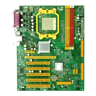
Page 9: Layout Diagram & Jumper Setting
Rear I / O for M2GT6-P & M2GT6-P-XW Motherboard 10/100 PRINTER COM1 Mbps LAN Line-IN PS/2 Mouse Line-OUT PS/2 Keyboard MIC-IN USB1 Rear I / O for M2GT6-PTD Motherboard 10/100 Mbps LAN PRINTER Line-IN PS/2 Mouse Line-OUT MIC-IN PS/2 Keyboard USB1 UL1 KBMS/USB Power On... - Page 10 3-pin Block P.19 CDIN CD Audio-In Header 4-pin Block P.20 COM2(Only for M2GT6-PTD) COM2 Header 9-pin Block P.20 TV-OUT(Only for M2GT6-PTD) TV-OUT Header 9-pin Block P.20 Expansion Sockets Socket/Slot Name Description Page ZIF Socket AM2 CPU Socket 940-pin mPGAB Athlon64 CPU Socket P.10...
-
Page 11: Chapter 2 Hardware Installation
Chapter 2 Hardware Installation 2-1 Hardware installation Steps Before using your computer, you had better complete the following steps: 1. Check motherboard jumper setting 2. Install CPU and Fan 3. Install System Memory (DIMM) 4. Install Expansion cards 5. Connect IDE and Floppy cables, Front Panel /Back Panel cable 6. - Page 12 (2) Keyboard function Enabled/Disabled: JP1 (3) USB Power On function Enabled/Disabled: JP5 1-2 closed USB Power On Disable 2-3 closed USB Power On Enabled (Default) USB Power On Setting (4) Keyboard function Enabled/Disabled: JP3 (5) USB Power On function Enabled/Disabled: JP2...
-
Page 13: Install Cpu
2-3 Install CPU 2-3-1 Glossary Chipset (or core logic) - two or more integrated circuits which control the interfaces between the system processor, RAM, I/O devises, and adapter cards. Processor slot/socket - the slot or socket used to mount the system processor on the motherboard. -
Page 14: About Amd Athlon64 940-Pin Cpu
2-3-2 About AMD Athlon64 Socket AM2 CPU This motherboard provides a 940-pin surface mount, Zero Insertion Force (ZIF) socket, referred to as the mPGA940 socket supports AMD Athlon64 processor in the 940 Pin package utilizes Flip-Chip Pin Grid Array package technology. The CPU that comes with the motherboard should have a cooling FAN attached to prevent overheating. -
Page 15: Install Memory
2-4 Install Memory The motherboards provide four 240-pin DDRII DUAL INLINE MEMORY MODULES (DIMM) sites for DDRII memory expansion available from minimum memory size of 128MB to maximum memory size of 8.0GB DDRII SDRAM. Valid Memory Configurations Bank 240-Pin DIMM Total Memory Bank 0, 1 (DIMM1) DDRII400/DDRII533/DDRII667/DDRII800... -
Page 16: Expansion Card
2-5 Expansion Cards WARNING! Turn off your power when adding or removing expansion cards or other system components. Failure to do so may cause severe damage to both your motherboard and expansion cards. 2-5-1 Procedure For Expansion Card Installation 1. Read the documentation for your expansion card and make any necessary hardware or software setting for your expansion card such as jumpers. -
Page 17: Pci-Express Slot
IMPORTANT! If using PCI cards on shared slots, make sure that the drivers support “Shared IRQ” or that the cards don’t need IRQ assignments. Conflicts will arise between the two PCI groups that will make the system unstable or cards inoperable. 2-5-4 PCI Express Slot One PCI-Express x16 graphics slot offers 4Gbyte/sec data transfer rate at each relative direction.), and one x1 PCI Express Slot. -
Page 18: Connectors, Headers
2-6 Connectors, Headers 2-6-1 Connectors (1) Power Connector (24-pin block) : ATXPWR ATX Power Supply connector. This is a new defined 24-pins connector that usually comes with ATX case. The ATX Power Supply allows to use soft power on momentary switch that connect from the front panel switch to 2-pins Power On jumper pole on the motherboard. - Page 19 CEN/LEF : (BLACKNESS) Audio output to speaker-Center/Subwoofer speaker out Surround: (GRAY) Audio output to speaker-Side speaker out VGA/Digital Video Interface: VGA/DVI (For M2GT6-PTD) DVI is the 24-pin Digital Video Interface female connector, it is for the display devices, such as the CRT monitor, LCD monitor and so on.
- Page 20 10 /100 PS/2 Mouse PRINTER Line-IN Line-OUT MIC-IN PS/2 COM1 Keyboard Floppy drive Connector (34-pin block): FDD This connector supports the provided floppy drive ribbon cable. After connecting the single plug end to motherboard, connect the two plugs at other end to the floppy drives. Pin 1 Floppy Drive Connector (10) Primary IDE Connector (40-pin block): IDE1...
- Page 21 IDE 2 Pin 1 Secondary IDE Connector • Two hard disks can be connected to each connector. The first HDD is referred to as the “Master” and the second HDD is referred to as the “Slave”. • For performance issues, we strongly suggest you don’t install a CD-ROM or DVD-ROM drive on the same IDE channel as a hard disk.
-
Page 22: Headers
2-6-2 Headers Line-Out/MIC Header for Front Panel (9-pin): AUDIO This header connect to Front Panel Line-out, MIC connector with cable. Without install the cable, this header default setting is 5-6 short, 9-10 short. When you install the cable you have take off these jumpers. AUDIO Pin 1 Line-Out, MIC Headers... - Page 23 Power switch: PWR BTN This 2-pin connector connects to the case-mounted power switch to power ON/OFF the system. PWRLED Pin 1 JW FP SPEAK Pin 1 Pin 1 System Case Connections FAN Headers (3-pin) : SYSFAN1, SYSFAN2, CPUFAN These connectors support cooling fans of 350mA (4.2 Watts) or less, depending on the fan manufacturer, the wire and plug may be different.
- Page 24 CD-Audio output connector. C DIN CD Audio-In Headers (10) COM2 Port: COM2(Only for M2GT6-PTD) Com2 is for the serial devices, such as the joystick, the scanner and so on. (11) TV-OUT Header: TV-OUT(Only for M2GT6-PTD) This 10 pin connector is for the TV-out port module that allows you to connect a television to your system.
-
Page 25: Starting Up Your Computer
2-7 Starting Up Your Computer 1. After all connection are made, close your computer case cover. 2. Be sure all the switch are off, and check that the power supply input voltage is set to proper position, usually in-put voltage is 220V∼240V or 110V∼120V depending on your country’s voltage used. -
Page 26: Chapter 3 Introducing Bios
Chapter 3 Introducing BIOS The BIOS is a program located on a Flash Memory on the motherboard. This program is a bridge between motherboard and operating system. When you start the computer, the BIOS program gain control. The BIOS first operates an auto-diagnostic test called POST (power on self test) for all the necessary hardware, it detects the entire hardware device and configures the parameters of the hardware synchronization. -
Page 27: The Main Menu
3-3 The Main Menu Once you enter Award ® BIOS CMOS Setup Utility, the Main Menu (Figure 3-1) will appear on the screen. The Main Menu allows you to select from fourteen setup functions and two exit choices. Use arrow keys to select among the items and press <Enter> to accept or enter the sub-menu. -
Page 28: Standard Cmos Features
Power User Overclock Settings Use this menu to specify your settings (frequency, Voltage) for overclocking demand Password Settings This entry for setting Supervisor password and User password Load Optimized Defaults Use this menu to load the BIOS default values these are setting for optimal performances system operations for performance use. -
Page 29: Advanced Bios Features
IDE Channel 0 Master / Channel 0 Slave / Channel 1 Master / Channel 0 Slave SATA Channel 1, 2, 3, 4 Press PgUp/<+> or PgDn/<–> to select Manual, None, Auto type. Note that the specifications of your drive must match with the drive table. The hard disk will not work properly if you enter improper information for this category. - Page 30 Hard Disk Boot Priority The selection is for you to choose the hard disk drives priorities to boot from. Virus Warning Allows you to choose the VIRUS Warning feature for IDE Hard Disk boot sector protection. If this function is enabled and someone attempt to write data into this area, BIOS will show a warning message on screen and alarm beep.
-
Page 31: Advanced Chipset Features
Typematic Rate (Chars/Sec) Sets the number of times a second to repeat a keystroke when you hold the key down. The settings are: 6, 8, 10, 12, 15, 20, 24, and 30. Typematic Delay (Msec) Sets the delay time after the key is held down before is begins to repeat the keystroke. The settings are 250, 500, 750, and 1000. -
Page 32: Dram Timing Settings
System BIOS Cacheable Selecting Enabled allows caching of the system BIOS ROM at F0000h-FFFFFh, resulting in better system performance. However, if any program writes to this memory area, a system error may result. The settings are: Enabled and Disabled. 3-6-1 DRAM Configuration Phoenix –... -
Page 33: Onchip Ide Function
OnChip IDE Function Please refer to section 3-7-1 OnChip Device Function Please refer to section 3-7-2 OnChip Super IO Function Please refer to section 3-7-3 Init Display First This item allows you to decide to activate whether PCI Slot or AGP VGA first. The settings are: PCI Slot, AGP Slot. -
Page 34: Onchip Device Function
IDE Prefatch The selection is for you to set the IDE device as the first priority to activate. IDE HDD Block Mode Block mode is also called block transfer, multiple commands, or multiple sector read/write. If your IDE hard drive supports block mode (most new drives do), select Enabled for automatic detection of the optimal number of block read/writes per sector the drive can support. -
Page 35: Onchip Super Io Function
3-7-3 Onchip Super IO Function Phoenix – AwardBIOS CMOS Setup Utility Onboard Super IO Function Onboard FDC Controller Enabled Item Help Onboard Serial Port 2 2F8/IRQ3 Onboard Parallel Port 378/IRQ7 Parallel Port Mode Menu Level >> ECP Mode Use DMA ↑↓→←... -
Page 36: Power Management Setup
3-8 Power Management Setup The Power Management Setup allows you to configure your system to most effectively save energy saving while operating in a manner consistent with your own style of computer use. Phoenix – AwardBIOS CMOS Setup Utility Power Management Setup PS2 KB/MS Wakeup by<S3/S4/S5>... -
Page 37: Miscellaneous Control
3-9 Miscellaneous Control This section is for setting CPU Frequency/Voltage Control. Phoenix – AwardBIOS CMOS Setup Utility Miscellaneous Control CPU Spread Spectrum Disabled Item Help PCIE Spread Spectrum Disabled SATA Spread Spectrum Disabled HT Spread Spectrum Disabled Menu Level > Reset Configuration Data Disabled IRQ Resources... -
Page 38: Pc Health Status
3-10 PC Health Status This section shows the Status of you CPU, Fan, Warning for overall system status. This is only available if there is Hardware Monitor onboard. Phoenix – AwardBIOS CMOS Setup Utility PC Health Status Item Help Show H/W Health in Post Enabled Shutdown Temperature Disabled... -
Page 39: Thermal Throttling Options
3-11 Thermal Throttling Options Phoenix – AwardBIOS CMOS Setup Utility Thermal Throttling Options CPU Thermal-Throttling Disabled Item Help CPU Throttling Temp CPU Throttling Duty 87.50% CPU Thermal-Throttling CPU Throttling Beep Enabled Menu Level > Disabled .....[ .....[ Enabled ↑↓:Move ENTER:Accept ESC:Abort ↑↓→←... - Page 40 CPU Thermal Throttling Temp This item allows you to activate the CPU Thermal Throttling function when the CPU temperature is over the value which you set to low down the CPU temperature when at high workload to protect processor from damage or accidental shutdown. Phoenix –...
-
Page 41: Power User Overclock Settings
3-12 Power User Overclock Settings Phoenix – AwardBIOS CMOS Setup Utility Power User Overclock Settings *** Current Host Frequency is *** Item Help CPU Clock at next boot is *** Current DRAM Frequency is *** DRAM Clock at next boot is Auto Menu Level >... - Page 42 Phoenix – AwardBIOS CMOS Setup Utility Power User Overclock Settings *** Current Host Frequency is *** Item Help CPU Clock at next boot is *** Current DRAM Frequency is *** DRAM Clock at next boot is Auto Menu Level > CPU Ratio Default CPU Vcore...
-
Page 43: Password Settings
3-13 Password Settings Phoenix – AwardBIOS CMOS Setup Utility Password Settings Item Help Set Supervisor Password Press Enter Set User Password Press Enter Menu Level > ↑↓→← Move Enter:Select +/-/PU/PD:Value F10:Save ESC:Exit F1:General Help F5:Previous Values F6:Optimized Defaults F7:Standard Defaults You can set either supervisor or user password, or both of them. -
Page 44: Chapter 4 Driver & Free Program Installation
Chapter 4 DRIVER & FREE PROGRAM INSTALLATION Check your package and there is A MAGIC INSTALL CD included. This CD consists of all DRIVERS you need and some free application programs and utility programs. In addition, this CD also include an auto detect software which can tell you which hardware is installed, and which DRIVERS needed so that your system can function properly. -
Page 45: Nforce Install Nforce Integrated Driver
Install nForce Integrated Driver nForce * nForce Integrated driver pack include following device driver: NVIDIA GART driver : If you are using an AGP VGA Card, please install NVIDIA AGP GART driver which provides service routines to your VGA driver and interface directly to the hardware for speedy graphic access. - Page 46 5. Please choose to install the NVIDIA firewall 6. If you want to install NVIDIA firewall and and Forceware Network Access Manager Forceware Network Access Manager utility Utility Driver for demanding on you own. 7. Select install complete software and Click 8.
-
Page 47: Sound Install Alc655 6-Channel Audio Driver
ALC655 6-Channel 4-2 SOUND install Audio Driver 1. Click SOUND when MAGIC INSTALL 2. Click NEXT When Realtek AC97Audio driver MENU appears windows appears 3. Click FINISH and restart your computer 4. Manual Sound Effect Setting 5. Speaker configuration setting 6. -
Page 48: Lan Install Realtek Rtl8201Cl 10/100M Lan Driver
4-3 LAN Realtek RTL8201CL 10/100M LAN Driver 1. Click LAN when Magic Install Menu appear 2. Click Next to install Marvell LAN driver 3. Please Accept the license agreement and read 4. Click Install to install driver and Click Finish the “Readme”... -
Page 49: Pc-Cillin Install Pc-Cillin 2006 Anti-Virus Program
4-5 PC-CILLIN Install PC-CILLIN 2006 Anti-virus program Click PC-CILLIN when MAGIC INSTALL Please select “Install program” when the MENU appears "Trend Micro internet security" installshield wizard windows appears This is license agreement, select "I Accept Click NEXT or choose Change to change the the terms"... -
Page 50: Pc-Health Install Myguard Hardware Monitor Utility
PC-HEALTH Install MyGuard Hardware monitor Utility 1. Click PC-HEALTH when MAGIC INSTALL 2. Click Next when Install shield wizard Window MENU appears appears, Choose destination location and click Next, when the start copy file windows appear, click next 3. Select Finish after setup complete 4. -
Page 51: How To Update Bios
X:\FLASH\AWDFLASH.EXE or download from our web site. STEP 3. Download and make a copy of the latest BIOS for M2GT6-P/M2GT6-P- XW/M2GT6-PTD motherboard series from the web site to your boot disc. STEP 4. Insert your boot disc into A:, start the computer, type “Awdflash A:\M2GT6xxx.BIN /SN/PY/CC/R”... -
Page 52: Nforce4 Platform Raid Function Installation
4-8 Nforce4 Platform RAID Function Installation Step 1. Please get into the location: BIOS setup \ Integrated Peripherals \ Onchip IDE function \ RAID Configuration to enable the RAID function and choose the RAID hard drive channel. Phoenix – AwardBIOS CMOS Setup Utility RAID Configuration RAID Enable Enabled... - Page 53 Step 3. Making RAID driver diskette before Install WindowsXP/2000 Before you install the Windows XP or Windows 2000, you will need to make a RAID driver diskette before you start to install the Operating System. How to make a RAID driver diskette? 1: Insert the diskette which is being formatted in floppy drive on a system which can start OS.
-
Page 54: Pro Magic Plus Function Introduction
4-9 Pro Magic Plus Function Introduction What’s Pro Magic Plus? Tired with reinstall OS each time when it doesn’t work? Does your computer often crash down or unable to work after installed new software? Have you had great loses and troubles because of computer problems? Still using time-consuming backup software that occupies lots of HD space? Pro Magic Plus- an instant system recovery software tailored to solve these problems for... - Page 55 NOTE: Functions of each version will differ from each other, and will be based on the function descriptions of each version. System Requirements ◇ First OS must be Windows 98 SE/ME/2000/XP ◇ Support Only Windows OS (No Linux) ◇ Windows server OS and Windows NT not supported ◇...
Need help?
Do you have a question about the M2GT6-PTD and is the answer not in the manual?
Questions and answers