Table of Contents
Advertisement
Quick Links
TECHNICAL MANUAL
Of
Intel H81 Express Chipset
Based Mini-ITX M/B
NO. G03-NC9VL-F
Revision: 1.0
Release date: January 16, 2014
Trademark:
* Specifications and Information contained in this documentation are furnished for information use only, and are
subject to change at any time without notice, and should not be construed as a commitment by manufacturer.
Advertisement
Table of Contents

Subscribe to Our Youtube Channel
Related Manuals for JETWAY MBD-J-JNC9VL-H81


Summary of Contents for JETWAY MBD-J-JNC9VL-H81
- Page 1 TECHNICAL MANUAL Intel H81 Express Chipset Based Mini-ITX M/B NO. G03-NC9VL-F Revision: 1.0 Release date: January 16, 2014 Trademark: * Specifications and Information contained in this documentation are furnished for information use only, and are subject to change at any time without notice, and should not be construed as a commitment by manufacturer.
- Page 2 Environmental Protection Announcement Do not dispose this electronic device into the trash while discarding. To minimize pollution and ensure environment protection of mother earth, please recycle.
-
Page 3: Table Of Contents
TABLE OF CONTENT ENVIRONMENTAL SAFETY INSTRUCTION ................iii USER’S NOTICE ........................iv MANUAL REVISION INFORMATION ..................iv ITEM CHECKLIST ........................iv CHAPTER 1 INTRODUCTION OF THE MOTHERBOARD FEATURE OF MOTHERBOARD ................1 SPECIFICATION ......................2 LAYOUT DIAGRAM ....................3 CHAPTER 2 HARDWARE INSTALLATION JUMPER SETTING ..................... -
Page 4: Environmental Safety Instruction
Environmental Safety Instruction Avoid the dusty, humidity and temperature extremes. Do not place the product in any area where it may become wet. 0 to 60 centigrade is the suitable temperature. (The figure comes from the request of the main chipset) ... -
Page 5: User's Notice
USER’S NOTICE COPYRIGHT OF THIS MANUAL BELONGS TO THE MANUFACTURER. NO PART OF THIS MANUAL, INCLUDING THE PRODUCTS AND SOFTWARE DESCRIBED IN IT MAY BE REPRODUCED, TRANSMITTED OR TRANSLATED INTO ANY LANGUAGE IN ANY FORM OR BY ANY MEANS WITHOUT WRITTEN PERMISSION OF THE MANUFACTURER. -
Page 6: Chapter 1 Introduction Of The Motherboard Feature Of Motherboard
Chapter 1 Introduction of the Motherboard Feature of Motherboard ® Intel H81 express chipset ® ® Support LGA 1150 CPU socket Intel Core™ i7 processors / Intel Core™ i5 ® ® processors / Intel Core™ i3 processors / Intel Celeron™... -
Page 7: Specification
1-2 Specification Spec Description Design Mini-ITX form factor 6 layers ; PCB size: 17.0x17.0cm Chipset Intel H81 Express Chipset ® ® Support Intel LGA 1150 Socket Core™ i7 Processor, Intel ® ® Core™ i5 Processor, Intel Core™ i3 Processor, Intel CPU Socket Celeron™... -
Page 8: Layout Diagram
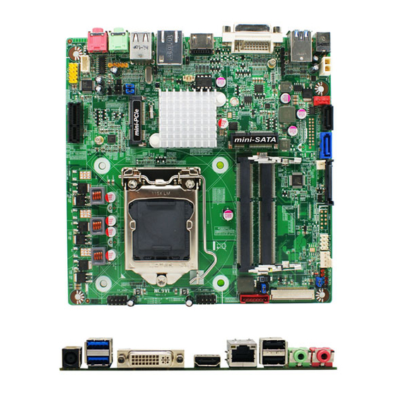
1*LINE-OUT jack 1* MIC-IN jack Internal I/O Connectors& Headers: 1 *2-pin ATX19V internal power connector 1 * SATA power connector 1 * PS2 Keyboard / Mouse header 1 * Case open header 1* CPUFAN header + 1* SYSFAN header ... - Page 9 Motherboard Internal Diagram CPUFAN Header SATA Power SATAII Port Connector (SATA2) Front Panel SYSFAN Header (SATA_POWER) ATX 19V Power CIR Header Header Connector 19V DC Power-in Jack MON_SW Header SATAIII Port USB 3.0 Ports (SATA1) 48-bit LVDS Connector PS2 KB & MS Header DDRIII SODIMM Slots Full-size MSATA Slot DVI-I Port...
- Page 10 Motherboard Jumper Position COPEN JBAT...
- Page 11 Connectors Connector Name DC_IN DC Adapter 19V ATX2P DC19V Power Connector USB1 USB 3.0 Connector X2 DVI-I DVI-I Connector HDMI High-Definition Multimedia Interface RJ-45 LAN Connector USB3 USB 2.0 Connector X2 FP_HP Front Panel Head Phone Connector FP_MIC Front Panel MIC Connector SATA_POWER SATA Power Connector SATA1...
-
Page 12: Chapter 2 Hardware Installation
PS2KBMS PS2 Keyboard & Mouse Header 6-pin Block LAN1LED1 LAN Activity LED Header 2-pin Block WIFI_LED WIFI Activity LED Header 2-pin Block BL_LED Blue Tooth Activity LED Header 2-pin Block Jumper Jumper Name Description Inverter VCC 12V/19V Select 3-pin Block LCD Power Source Setting 4-pin Block MINI_ HALF Slot VCC 3.3V/ 3.3VSB Select 3-pin Block... - Page 13 (2) JP2 (4-pin): LCD Power Source Setting JP2→LVDS Backlight VCC 2-4 Closed: LVDS 3-4 Closed: LVDS 4-6 Closed: LVDS VCC= 3.3V; VCC= 5V; VCC= 12V. (3) JP4 (3-pin): MINI_HALF Slot VCC3.3V/ 3.3VSB Select JP4→MINI_HALF Slot VCC 1-2 Closed: MINI_HALF Slot VCC= 3.3V; 2-3 Closed: MINI_HALF Slot VCC=3.3VSB.
- Page 14 (4) JBAT (3-pin): Clear CMOS Function Setting JBAT 1-2 Closed: Normal; 2-3 Closed:Clear CMOS. CMOS Clear Setting (5)COPEN1 (2-pin): Case Open Message Display Function Select COPEN1 Pin 1-2 Closed: When Case open function pin short to GND, The Case open function was detected.
-
Page 15: Connectors And Headers
Connectors and Headers 2-2-1 Connectors (1) Rear Panel Connectors USB 3.0 Ports RJ-45 LAN Port DVI-I Port MIC-IN 19V DC Power-in Jack USB 2.0 Ports HDMI Port Line-OUT (2) ATX2P (2-pin block): ATX19V Type power connector Pin1 Pin No. Definition +19V... - Page 16 (3) SATA_POWER (15-pin block): SATA power connector Pin1 SA TA Pow er C onnector Pin NO. Definition Pin 1 3.3V Pin 2 3.3V Pin 3 3.3V Pin 4 GND1 Pin 5 GND1 Pin 6 GND1 Pin 7 Pin 8 Pin 9 Pin 10 GND2 Pin 11...
- Page 17 (5) SATA2(7-pin): SATA II Port connector This connector is a fast-speed SATAII port that supports 3 GB/s transfer rate. Pin No. Defnition (6)SPEAK_CON (4-pin block): Speaker Connector Pin1 SPEAK _CON Pin No. Definition...
- Page 18 (7) LVDS(40-pin): 48-bit LVDS Header Pin NO. Pin Define Pin NO. Pin Define Pin 1 LVDSA_DATAP3 Pin 2 LVDSA_DATAN3 Pin 3 LVDSA_DATAP2 Pin 4 LVDSA_DATAN2 Pin 5 LVDSA_DATAP1 Pin 6 LVDSA_DATAN1 Pin 7 LVDSA_DATAP0 Pin 8 LVDSA_DATAN0 Pin 9 LVDSB_DATAP3 Pin 10 LVDSB _DATAN3 Pin 11...
- Page 19 (8) INVERTER (8-pin): LVDS Inverter Connector Pin No. Definition Backlight Enable Backlight Duty Pin 1 PVCC PVCC Backlight +SW Backlight -SW (9) CPUFAN/SYSFAN (4-pin): Fan Connector Conrol Fan Clock +12V Fan Power Pin1 Pin1 SYSFAN CPUFAN...
-
Page 20: Headers
2-2-2 Headers (1) FP_AUDIO (9-pin): Line-Out, MIC-In Header This header connects to Front Panel Line-out, MIC-In connector with cable. FP_AUDIO Pin 1 Line-Out, MIC Headers (2) DMIC_CON (4-Pin): DMIC Header Pin 1 V CC3 DMIC_DATA DMIC_CLK... - Page 21 (3)F_USB1/F_USB2 (9-pin): USB 2.0 Port Headers Pin 1 -DATA -DATA +DATA +DATA F_USB1/F_USB2 Header (4) JW-FP (9-pin): Front Panel Header JW_FP Pin 1...
- Page 22 (5) CIR_CON (7-Pin): CIR Header Pin 1 CIR Header (6) MON_SW (2-Pin): Monitor Switch Header Pin1 LVDS Display on/off MON_SW Header...
- Page 23 (7) PS2KBMS (6-pin): PS/2 Keyboard & Mouse Header Pin1 (8) LAN1_LED1 (2-pin): LAN Activity LED Header Pin1 LAN1_LED1 Header...
- Page 24 (9) WIFI_LED (2-pin): WIFI Activity LED Header Pin1 WIFI_LED Header (10) BL_LED (2-pin): Blue Tooth Activity LED Header Pin1 Blue Tooth LED+ Blue Tooth LED - BL_LED Header...
-
Page 25: Chapter 3 Introducing Bios
Chapter 3 Introducing BIOS Notice! The BIOS options in this manual are for reference only. Different configurations may lead to difference in BIOS screen and BIOS screens in manuals are usually the first BIOS version when the board is released and may be different from your purchased motherboard. -
Page 26: Bios Menu Screen
BIOS Menu Screen The following diagram show a general BIOS menu screen: Menu Bar General Help Items Current Setting Value Menu Items Function Keys BIOS Menu Screen Function Keys In the above BIOS Setup main menu of, you can see several options. We will explain these options step by step in the following pages of this chapter, but let us first see a short description of the function keys you may use here: ... -
Page 27: Getting Help
Press <Enter> to select. Press <+>/<–> keys when you want to modify the BIOS parameters for the active option. [F1]: General help. [F2]: Previous value. [F3]: Optimized defaults. [F4]: Save & Exit. Press [Esc] to quit the BIOS Setup. Getting Help Main Menu The on-line description of the highlighted setup function is displayed at the top right... -
Page 28: Main Menu
Main Menu Main menu screen includes some basic system information. Highlight the item and then use the <+> or <-> and numerical keyboard keys to select the value you want in each item. Select Language This item is for user to choose the system default language. System Date Set the date. -
Page 29: Advanced Menu
3-7 Advanced Menu CPU Configuration Press [Enter] user can have a view of CPU basic information and make settings in sub-items. Limit CPUID Maximum The optional settings are: [Disabled]; [Enabled]. This item should be set as [Disabled] for Windows XP. Execute Disable Bit The optional settings are: [Disabled];... - Page 30 Hardware Prefetcher Use this item to enabled or disable the Mid Level Cache (L2) streamer prefetcher. Adjacent Cache Line Prefetch Use this item to enabled or disable prefetching of adjacent cache lines. EIST Use this item to enable or disable Intel Speed Step. The optional settings are: [Disabled];...
- Page 31 USB Transfer time-out Use this item to set the time-out value for control, bulk, and interrupt transfers. The optional settings are: [1 sec]; [5 sec]; [10 sec]; [20 sec]. Device reset time-out Use this item to set USB mass storage device start unit command time-out. The optional settings are: [10 sec];...
- Page 32 PS2 KB/MS Wake-UP from S3-S5 *This item will only show when ‘ERP Support’ is set as [Disabled]. PS2 KB/MS Wake-UP is affected by ERP Function in S4-S5. Please disable ERP before activating this function in S4-S5. The optional settings are: [Disabled]; [Enabled]. WatchDog Timer The optional settings are: [Disabled];...
- Page 33 Use this item to set CPUFAN/SYSFAN full speed temperature. Fan will run at full speed when above this temperature. CPUFAN / SYSFAN Full-Speed Duty Use this item to set CPUFAN/ SYSFAN full speed duty. Fan will run at full speed when above the pre-set duty.
- Page 34 S3-S5 RTC Wake-up Settings This item is for user to enable the system wake on RTC alarm from S3-S5. RTC alarm is affected by ERP function in S4-S5. Please disable ERP before activating RTC alarm in S4-S5. Wake-up System with Fixed Time Use this item to enable or disable system wake-up by RTC alarm.
-
Page 35: Chipset Menu
[100 Mbps Half]; [10 Mbps Full]. Wake On LAN Use this item to enable the server to be powered on using an in-band magic packet. The optional settings are: [Disabled]; [Enabled]. Blink LEDs This item identifies the physical network port by blinking the associated LED. Driver Health This item provides Health Status for the Drivers/Controllers. - Page 36 PCH-IO Configuration Press [Enter] to make further settings for PCH parameters. PCIE Slot The optional settings are: [Disabled]; [Enabled]. PCIE Slot Speed The optional settings are: [Auto]; [Gen1]; [Gen2]. Detect Non-Compliance Device Use this item to detect non-compliance PCI Express device. When set as [Enabled], it will take more time at POST time.
- Page 37 always be enabled. USB0/USB1 Wake-up from S3-S4 *This item will only show when ‘ERP Support’ is set as [Disabled]. The optional settings are: [Disabled]; [Enabled]. USB wake up is affected by ERP function in S4. Please disable ERP before activating this function in S4. USB2/USB3 Wake-up from S3-S4 *This item will only show when ‘ERP Support’...
- Page 38 display. The optional settings are: [VBIOS Default]; [DVI]; [HDMI]. Secondary IGFX Boot Display The optional settings are: [Disabled]; [DVI]; [HDMI]. *The optional setting [HDMI] will only show up when ‘Primary IGFX Boot Display’ is set as [DVI]. DVI to CRT Dongle Support The optional settings are: [Disabled];...
-
Page 39: Boot Menu
3-9 Boot Menu Boot Configuration Setup Prompt Timeout Use this item to set number of seconds to wait for setup activation key. Bootup Numlock State Use this item to select keyboard numlock state. The optional settings are: [On]; [Off]. Quiet Boot The optional settings are: [Enabled];... - Page 40 CSM parameters Press [Enter] to make settings for the following sub-items: Boot option filter This option controls what device system can boot to. The optional settings are: [UEFI and Legacy]; [Legacy only]; [UEFI only]. Launch PXE OpROM policy This option controls the execution of UEFI and Legacy PXE OpROM. The optional settings are: [Do not launch];...
-
Page 41: Security Menu
3-10 Security Menu Security menu allow users to change administrator password and user password settings. -
Page 42: Save & Exit Menu
3-11 Save & Exit Menu Save Changes and Reset This item allows user to reset the system after saving the changes. Discard Changes and Reset This item allows user to reset the system without saving any changes. Save Changes This item allows user to save changes done so far to any of the setup options. Discard Changes This item allows user to discard changes done so far to any of the setup options. - Page 43 Save as User Defaults Use this item to save the changes done so far as user defaults. Restore User Defaults Use this item to restore defaults to all the setup options.
Need help?
Do you have a question about the MBD-J-JNC9VL-H81 and is the answer not in the manual?
Questions and answers