Table of Contents
Advertisement
Quick Links
MI215 Series
User's Manual
NO. G03-MI215-F
Revision: 1.0
Release date: July 4, 2023
Trademark:
* Specifications and Information contained in this documentation are furnished for information use only, and are
subject to change at any time without notice, and should not be construed as a commitment by manufacturer.
Advertisement
Table of Contents

Subscribe to Our Youtube Channel
Related Manuals for JETWAY MI215 Series


Summary of Contents for JETWAY MI215 Series
- Page 1 MI215 Series User’s Manual NO. G03-MI215-F Revision: 1.0 Release date: July 4, 2023 Trademark: * Specifications and Information contained in this documentation are furnished for information use only, and are subject to change at any time without notice, and should not be construed as a commitment by manufacturer.
- Page 2 Environmental Protection Announcement Do not dispose this electronic device into the trash while discarding. To minimize pollution and ensure environment protection of mother earth, please recycle.
-
Page 3: Table Of Contents
TABLE OF CONTENT ENVIRONMENTAL SAFETY INSTRUCTION................iii USER’S NOTICE..........................iv MANUAL REVISION INFORMATION...................iv ITEM CHECKLIST..........................iv CHAPTER 1 INTRODUCTION OF THE MOTHERBOARD FEATURE OF MOTHERBOARD..................1 SPECIFICATION........................2 LAYOUT DIAGRAM.......................4 CHAPTER 2 HARDWARE INSTALLATION JUMPER SETTING........................ 10 CONNECTORS, HEADERS AND WAFERS..............14 2-2-1 REAR I/O BACK PANEL CONNECTORS............ -
Page 4: Environmental Safety Instruction
Environmental Safety Instruction Avoid the dusty, humidity and temperature extremes. Do not place the product in any area where it may become wet. 0 to 40 centigrade is the suitable temperature. (The temperature comes from the request of the chassis and thermal solution) ... -
Page 5: User's Notice
USER’S NOTICE COPYRIGHT OF THIS MANUAL BELONGS TO THE MANUFACTURER. NO PART OF THIS MANUAL, INCLUDING THE PRODUCTS AND SOFTWARE DESCRIBED IN IT MAY BE REPRODUCED, TRANSMITTED OR TRANSLATED INTO ANY LANGUAGE IN ANY FORM OR BY ANY MEANS WITHOUT WRITTEN PERMISSION OF THE MANUFACTURER. -
Page 6: Chapter 1 Introduction Of The Motherboard
Chapter 1 Introduction of the Motherboard 1-1 Feature of Motherboard Intel LGA1700 Socket supports 12 Gen. Core Processor (Max. 65W TDPs ® under 180A) Support 2* DDR5 4800MHz SO-DIMM up to 64GB Integrated with 2* Intel 2.5GbE PCIe LAN chips ®... -
Page 7: Specification
1-2 Specification Spec Description Design Slim Mini-ITX form factor; 10-layers; PCB size: 17.0x17.0cm MI215H6100 Series: Intel H610E/H610 Chipset (Default: H610) ® Chipset MI215Q6700 Series: Intel Q670E Chipset ® MI215R6800 Series: Intel R680E Chipset ® Intel LGA 1700 Socket supports 12 Gen. - Page 8 MI215H6100: 2* Intel i225-V 2.5GbE PCIe LAN chip Support 10/100/1000/2500Mbps Ethernet data transfer rate *Note: 2500Mbps high-speed transmission rate is only supported over CAT 5e UTP cable. Realtek HD Audio Codec integrated Audio Chip Audio driver and utility included ...
-
Page 9: Layout Diagram
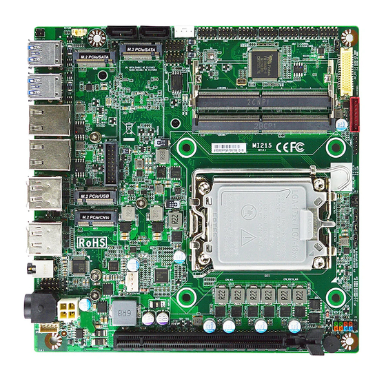
1-3 Layout Diagram Rear IO Diagram For MI215R6800/ MI215Q6700 Series: 2.5GbE RJ-45 DisplayPorts LAN Ports (2.5 GbE) 12V~36V DC-in Power Jack HDMI Ports USB 3.2 (Gen.2) Line-Out/MIC Combo Ports Audio Jack For MI215H6100 Series: 2.5GbE RJ-45 DisplayPorts LAN Ports USB 2.0 Port (2.5 GbE) 12V~36V DC-in Power Jack... - Page 10 Motherboard Internal Diagram-Front SATAIII Ports Serial Port Headers BATCON (SATA1/2) PWROUT (COM1/2/3/4/5/6) GPIO Header USB2.0 Headers (FP_USB1/*FP_USB2) LVDS_EDP DDR5 SODIMM Slot x 2 M.2 M-Key Slot (*M2M2) M.2 M-Key Slot INVERTER1 M.2 B-Key Slot (M2M1) (M2B1) SMBUS1 Header USB 3.2(Gen.1) *Rear IO Header Connector...
- Page 11 Motherboard Internal Diagram-Back *SIMCARDB1 *Note: SIM card slot only workable along with M.2 B-key slot.
- Page 12 Motherboard Jumper Position COPEN JBAT JAT_ATX *Note: The diagrams in the manual are mostly taken from MI215Q6700/R6800 series for illustration purpose, unless otherwise stated.
- Page 13 Jumper Name Description Pitch JBAT Clear CMOS RAM Settings 3-pin Block 2.0mm ME_Features Select 2-pin Block 2.0mm COPEN Case Open Message Display Function 2-pin Block 2.0mm LVDS_EDP VDD Select 4-pin Block 2.0mm INVERTER1 Backlight VCC Select 3-pin Block 2.0mm JAT_ATX ATX Mode / AT Mode Select 3-pin Block 2.0mm...
- Page 14 Headers & Wafers Name Description Pitch 9-pin Block PWR LED/ HD LED/Power Button /Reset 2.54mm (Front Panel Header) FP_AUDIO 9-pin Block 2.0mm Front Panel Audio Header SPEAK_CON 4-pin Block 2.0mm 3W 8ΩAmplifier Wafer COM1/2 RS232/422/485 Serial Port Header 9-pin Block 2.0mm COM3/4/5/6 RS232 Serial Port Header...
-
Page 15: Chapter 2 Hardware Installation
Chapter 2 Hardware Installation 2-1 Jumper Setting JBAT (3-pin): Clear CMOS RAM Settings JBAT Clear CMOS RAM Settings → JBAT 1-2 Closed: Normal(default); 2-3 Closed: Clear CMOS. JP1(2-pin): ME_Features Select JP1 → ME_Features Select Pin1 1-2 Open: Enable ME_Features(default); Pin1 1-2 Closed: Disable ME_Features. - Page 16 COPEN (2-pin): Case Open Message Display Function COPEN COPEN → Case Open Detection Pin1 CASE OPEN Pin 1-2 Short: When Case open function pin short to GND, the Case open function was detected. When Used, needs to enter BIOS and enable ‘Case Open Detect’ function. In this case if your case is removed, next time when you restart your computer, a message will be displayed on screen to inform you of this.
- Page 17 JP5(3-pin):INVERTER1 Backlight VCC Select INVERTER1 Backlight VCC Select → 1-2 Closed: VCC=5V(default); 2-3 Closed: VCC=12V. **Warning! Wrong voltage setting will result in screen burn out. JAT_ATX (3-pin): AT Mode /ATX Mode Select JAT_ATX → ATX/AT Mode Select JAT_ATX 1-2 Closed: ATX Mode Selected(default); 2-3 Closed: AT Mode Selected.
- Page 18 JP4(2-pin): GPIO Header Function Select JP4 → GPIO Function Select Pin1 1-2 Open: Function as 80 Port; Pin1 1-2 Closed:Function as GPIO Port(default).
-
Page 19: Connectors, Headers And Wafers
2-2 Connectors, Headers & Wafers 2-2-1 Rear I/O Back Panel Connectors *Refer to Page-4 Rear IO Diagram Icon Name Function To connect USB keyboard, mouse or other devices USB 3.2 (Gen.2) compatible with USB 3.2 (Gen.2) specification. Ports Port support up to 10Gbps data transfer rate. Top: To connect USB keyboard, mouse or other devices compatible with USB 2.0 specification. - Page 20 Line_Out/MIC Combo This connector can functions as audio Line-Out jack Audio Jack and MIC jack with compatible cables & devices. Mini-DIN For user to connect compatible power adapter to Power Jack provide power supply for the system. This connector is standard RJ-45 LAN jack for Network connection which 2.5Gbps supports10/100/1000/2500 Mbps Ethernet data...
- Page 21 (2) DCIN3: Mini-DIN 12V~36V Wide-Voltage DC-In Power Connector 2.5GbE RJ-45 LAN Ports (2.5 GbE) 12~36V DC-in Power Jack Pin1 Pin2 Pin3 Pin4 Pin No. Definition +12V~36V DC_IN +12V~36V DC_IN DCIN3 Warning!! The board has a 12V~36V DC-in power connector (DCIN3) on I/O back panel and an internal 12V~36V power connector (DCIN2).
-
Page 22: Motherboard Internal Connectors
2-2-2 Motherboard Internal Connectors (1) DCIN2 (4-pin block): Internal 12V~36V Wide-Voltage Power Connector Pin1 Pin No. Definition +12V~36V DCIN2 +12V~36V (2) SATA1/2 (7-pin): SATA III Port connector These are high-speed SATAIII port that supports 6 GB/s transfer rate. - Page 23 (3) PWROUT (4-pin): HDD Power-Out connector PWROUT Pin1 (4) CPUFAN1 (4-pin): CPU FAN Connector Pin1 +12V Fan Power Fan Speed Control CPUFAN1...
-
Page 24: Pin Definition For Headers & Wafers
(5) BATCON (2-pin): Battery Connector BATCON 2-2-3 Pin Definition for Headers & Wafers FP (9-pin): Front Panel Header... - Page 25 FP_AUDIO (9-pin): Line-Out, MIC-In Header This header is connected to Front Panel Line-out, MIC connector with cable. FP_AUDIO Pin 1 SPEAK_CON (4-pin): 3W 8ΩAmplifier Wafer Pin1 SPEAK_CON...
- Page 26 COM1/2/3/4/5/6(9-pin): Serial Port Headers *COM1/2: RS232/422/485 Serial Port Header. COM3/4/5/6: RS232 Serial Port Header. *COM1 Pin NO. RS232 *RS422 *RS485 *COM2 (optional) (optional) Pin 1 DCD - DATA- COM3 Pin 2 SIN - DATA+ COM6 COM4 Pin 3 SOUT - COM5 Pin 4 DTR -...
- Page 27 FP_USB1/*FP_USB2 (9-pin): USB 2.0 Port Header FP_USB1 *FP_USB2 (Optional) Pin 1 *Note:FP_USB2 is only optional to MI215Q6700/R6800 series. *FP_USB3 (19-pin): USB 3.2(Gen.1) Port Header Pin1 VBUS_5V VBUS_5V SSRX1- SSRX2- SSRX1+ *FP_USB3 SSRX2+ GND0 GND3 Optional SSTX1- SSTX2- SSTX1+ SSTX2+ GND1 GND2 *Note:FP_USB3 is only optional to MI215Q6700/R6800 series.
- Page 28 GPIO (10-pin): 8-bit GPIO/80 Port Header JP4 Open: For 80Port Function; JP4 Closed: Normal 8-bit GPIO. GPIO Pin1 *Note: GPIO can function as Debug display port or GPIO port via JP4 jumper setting (refer to Page-13 for JP4 description). SMBUS1 (5-Pin): SMBUS Header Pin1 SMBUS_CLK SMBUS_DATA...
- Page 29 LVDS_EDP (30-Pin): LVDS/EDP LCD Panel Wafer LVDS_EDP Pin Define Pin NO. Pin NO. Pin Define LVDSB_DATAN3 Pin 1 Pin 2 LVDSB_DATAP3 LVDSB_CLKN Pin 3 Pin 4 LVDSB_CLKP LVDSB_DATAN2 Pin 5 Pin 6 LVDSB_DATAP2 LVDSB_DATAN1 Pin 7 Pin 8 LVDSB_DATAP1 LVDSB_DATAN0 Pin 9 Pin 10 LVDSB_DATAP0...
- Page 30 INVERTER1 (8-pin): LVDS/eDP Inverter Connector Pin No. Definition Backlight Enable Backlight PWM PVCC PVCC INVERTER1 Backlight Up SW Backlight Down SW Warning! Find Pin-1 location of the inverter and make sure that the installation direction is correct! Otherwise serious harm will occur to the board/display panel!!
-
Page 31: Maximum Voltage & Current Limit
2-3 Maximum Voltage & Current Limit Below is a list of maximum voltage & Current Limit specification for motherboard interface (including but not limited to slots, connectors and headers) for setup reference: Parts Working Voltage Current Support USB1 USB2 1.5A USB Ports from FP_USB1 1.5A... -
Page 32: Chapter 3 Introducing Bios
Chapter 3 Introducing BIOS Notice! The BIOS options in this manual are for reference only. Different configurations may lead to difference in BIOS screen and BIOS screens in manuals are usually the first BIOS version when the board is released and may be different from your purchased motherboard. -
Page 33: Bios Menu Screen
3-2 BIOS Menu Screen The following diagram show a general BIOS menu screen: Menu Bar BIOS Menu Screen General Help Items Menu Items Current Setting Value Function Keys... -
Page 34: Function Keys
3-3 Function Keys In the above BIOS Setup main menu of, you can see several options. We will explain these options step by step in the following pages of this chapter, but let us first see a short description of the function keys you may use here: ... -
Page 35: Menu Bar
3-5 Menu Bars There are six menu bars on top of BIOS screen: Main To change system basic configuration Advanced To change system advanced configuration Chipset To change chipset configuration Security Password settings Boot To change boot settings Save & Exit Save setting, loading and exit options. -
Page 36: Advanced Menu
System Date Set the date. Please use [Tab] to switch between date elements. System Time Set the time. Please use [Tab] to switch between time elements. 3-7 Advanced Menu BIOS screen from MI215 series with Q6700 and R6800 chipset:... - Page 37 BIOS screen from MI215 series with H6100 chipset: Connectivity Configuration Press [Enter] to make settings for the following sub-item: CNVi Mode This option configures connectivity. [Auto Detection] means that if Discrete solution is discovered it will be enabled by default.
- Page 38 When enabled, a VHM can utilize the additional hardware capabilities provided by Vanderpool Technology. The optional settings: [Disabled]; [Enabled]. Intel (R) SpeedStep ™ Use this item to Allows more than two frequency ranges to be supported. The optional settings: [Disabled]; [Enabled]. C states Use this item to enable/disable CPU Power management.
- Page 39 Hot Plug Use this item to designates this port as Hot Pluggable. The optional settings are: [Enabled]; [Disabled]. PCH-FW Configuration Use this item to configure Management engine technology parameters Press [Enter] to make settings for the following sub-items: TPM Device Selection Use this item to selects TPM device: PTT or dTPM.
- Page 40 Press [Enter] to make settings for the following sub-items: ACPI Settings ACPI Sleep State Use this item to select the highest ACPI sleep state the system will enter when the suspend button is pressed. The optional settings are: [Suspend Disabled]; [S3 (Suspend to RAM)]. ►...
- Page 41 Use this item to USB Power after system shutdown support only disable ERP function The optional settings: [Disabled]; [Enabled]. Super IO Configuration Press [Enter] to make settings for the following sub-items: Super IO Configuration ERP Support Use this item to energy-related products function. Disable ERP to active all wake-up functions.
- Page 42 Use this item to select an optimal setting for super IO device. The optional settings are: [IO=2F8h; IRQ=3]; [IO=3F8h; IRQ=3,4,5,7,10,11]; [IO=2F8h; IRQ=3,4,5,7,10,11]; [IO=3E8h; IRQ=3,4,5,7,10,11]; [IO=2E8h; IRQ=3,4,5,7,10,11]; Transmission Mode Select The optional settings are: [RS422]; [RS232]; [RS485] Mode Speed Select Use this item to RS232/RS422/RS485 Speed Select The optional settings: [RS232/RS422/RS485=250Kbps];...
- Page 43 Use this item to enable or disable serial port (COM). The optional settings: [Disabled]; [Enabled]. Change Settings Use this item to select an optimal setting for super IO device. The optional settings are: [IO=3E0h; IRQ=11]; [IO=3F8h; IRQ=3,4,5,7,10,11]; [IO=2F8h; IRQ=3,4,5,7,10,11]; [IO=3E8h; IRQ=3,4,5,7,10,11]; [IO=2E8h; IRQ=3,4,5,7,10,11];...
- Page 44 When set as [Enabled], system will detect if COPEN has been short or not (refer to COPEN jumper setting for Case Open Detection); if Pin 1&2 of COPEN are short, system will show Case Open Message during POST. ► PC Health Status Press [Enter] to view current hardware health status, make further settings in ‘SmartFAN Configuration’...
- Page 45 Console Redirection Settings The settings specify how the host computer and the remote computer (which the user is using) will exchange data. Both computers should have the same or compatible settings. Press [Enter] to make settings for the following sub-items: Terminal Type The optional settings: [VT100];...
- Page 46 the buffers are empty, a “start” signal can be sent to re-start the flow. Hardware flow control uses two wires to send start/stop signals. The optional settings: [None]; [Hardware RTS/CTS]. VT-UTF8 Combo Key Support Use this item to enable VT-UTF8 Combination Key Support for ANSI/VT100 terminals.
- Page 47 Serial Port for Out-of-Band Management/ Windows Emergency Management Services (EMS) Console Redirection EMS The optional settings: [Disabled]; [Enabled]. When set as [Enabled], user can make further settings in ‘Console Redirection Settings’ screen: Console Redirection Settings The settings specify how the host computer and the remote computer (which the user is using) will exchange data.
- Page 48 The default setting is: [1]. *This item may or may not show up, depending on different configuration. ► USB Configuration Press [Enter] to make settings for the following sub-items: USB Configuration XHCI Hand-off This is a workaround for OSes without XHCI hand-off support. The XHCI ownership change should be claimed by XHCI driver.
- Page 49 IPv4 PXE Support Use this item to enable IPv4 PXE Boot Support. When set as [Disabled], IPv4 PXE boot option will not be created. The optional settings: [Disabled]; [Enabled]. Ipv6 PXE Support Use this item to enable IPv6 PXE Boot Support. When set as [Disabled], IPv6 PXE boot option will not be created.
-
Page 50: Chipset Menu
3-8 Chipset Menu System Agent (SA) Configuration Press [Enter] to make settings for the following sub-items: Memory Configuration Maximum Memory Frequency Use this item to maximum memory frequency selections in Mhz The optional settings are: [Auto]; [4000]; [4400]; [4800]; [5000]; [5200]; [5400]; [5600]. - Page 51 *Note: optional for MI215 series with Q6700 and R6800 chipset eDP/LVDS Use this item to select the active configuration. The optional settings: [Disabled]; [Enabled] When set as [Enabled], the following sub-items shall appear: Panel Type Use this item to panel type The optional settings: [800*480 18bit Single];...
- Page 52 The optional settings: [128M]; [256M]; [Max] VMD setup menu Press [Enter] to make settings for the following sub-items: Enable VMD controller Use this item to enable/disable to VMD controller The optional settings: [Disabled]; [Enabled]. When set as [Enabled], the following sub-items shall appear: Enable VMD Global Mapping Use this item to enable/disable to VMD global mapping The optional settings: [Disabled];...
-
Page 53: Security Menu
3-9 Security Menu Security menu allow users to change administrator password and user password settings. Administrator Password If there is no password present on system, please press [Enter] to create new administrator password. If password is present on system, please press [Enter] to verify old password then to clear/change password. - Page 54 Secure Boot feature is Active if Secure Boot is Enabled, Platform Key(PK) is enrolled and the System is in User mode. The mode change requires platform reset. The optional settings: [Disabled]; [Enabled]. Secure Boot Mode Set UEFI Secure Boot Mode to Standard mode or Custom mode. This change is effective after save.
-
Page 55: Boot Menu
Export Secure Boot variables Use this item to copy NVRAM content of Secure Boot variables to files in a root folder on a file system device. Secure Boot variable/Size/Keys/Key Source Platform Key(PK)/Key Exchange Keys/Authorized Signatures/Forbidden Signatures/ Authorized TimeStamps/OsRecovery Signatures Use this item to enroll Factory Defaults or load certificates from a file: 1. -
Page 56: Save & Exit Menu
Boot Configuration Setup Prompt Timeout Use this item to set number of seconds to wait for setup activation key. 65535(0Xffff) means indefinite waiting Bootup Numlock State Use this item to select keyboard numlock state. The optional settings are: [On]; [Off]. ... -
Page 57: Mebx
Discard Changes and Reset This item allows user to reset the system without saving any changes. Restore Defaults Use this item to restore /load default values for all the setup options. Save as User Defaults Use this item to save the changes done so far as user defaults. ...
Need help?
Do you have a question about the MI215 Series and is the answer not in the manual?
Questions and answers