Table of Contents
Advertisement
Quick Links
USER'S MANUAL
Of
MCP61P Chipset
Series Quad Core
M/B for Socket AM3
AMD Processor
NO. G03-M26GT4SVM-F
Rev: 2.0
Release date: November. 2010
Trademark:
* Specifications and Information contained in this documentation are furnished for information use only, and are
subject to change at any time without notice, and should not be construed as a commitment by manufacturer.
Advertisement
Table of Contents

Subscribe to Our Youtube Channel
Related Manuals for JETWAY M26GT4SVM


Summary of Contents for JETWAY M26GT4SVM
- Page 1 USER'S MANUAL MCP61P Chipset Series Quad Core M/B for Socket AM3 AMD Processor NO. G03-M26GT4SVM-F Rev: 2.0 Release date: November. 2010 Trademark: * Specifications and Information contained in this documentation are furnished for information use only, and are subject to change at any time without notice, and should not be construed as a commitment by manufacturer.
- Page 2 Environmental Safety Instruction Avoid the dusty, humidity and temperature extremes. Do not place the product in any area where it may become wet. 0 to 40 centigrade is the suitable temperature. (The figure comes from the request of the main chipset) Generally speaking, dramatic changes in temperature may lead to contact malfunction and crackles due to constant thermal expansion and contraction from the welding spots’...
-
Page 3: Table Of Contents
TABLE OF CONTENT CHAPTER 1 INTRODUCTION OF MCP61P MOTHERBOARD SERIES FEATURES OF MOTHERBOARD ................1 1-1.1 SPECIAL FEATURES OF MOTHERBOARD ..........2 SPECIFICATION ......................3 ITEM CHECKLIST....................... 3 LAYOUT DIAGRAM ....................4 CHAPTER 2 HARDWARE INSTALLATION CPU INSTALLATION....................5 INSTALL MEMORY ....................6 EXPANSION CARDS.................... -
Page 4: Chapter 1 Introduction Of Mcp61P Motherboard Series Features Of Motherboard
Chapter 1 Introduction of MCP61P Motherboard Series Features of motherboard The MCP61P Platform Processor Chipset motherboard series are based on the latest MCP61P Platform Processor Chipset which supports the following AM3 CPU under the 95W: Phenom II x 4;Phenom II x 3;Phenom II x2;Athlon II x4;Athlon II x3;Athlon II x2;Sempron. -
Page 5: 1-1.1 Special Features Of Motherboard
Some special features---CPU Thermal Throttling/ CPU VID/CPU Smart FAN in this motherboard are designed for power user to use the over-clocking function in more flexible ways. But please be caution that the over-clocking maybe causes the fails in system reliabilities. This motherboard provides the guaranteed performance and meets the demands of the next generation computing. -
Page 6: Specification
Specification Spec Description ∗ PCB size: 22.5cm*17.7cm Design ∗ Chipset MCP61P Chipset ∗ Support Phenom II x 4 ; Phenom II x 3 ; Phenom II x2 ; CPU Socket Athlon II x4 ; Athlon II x3 ; Athlon II x2 ; Sempron series AM3 CPU under 95W. -
Page 7: Layout Diagram
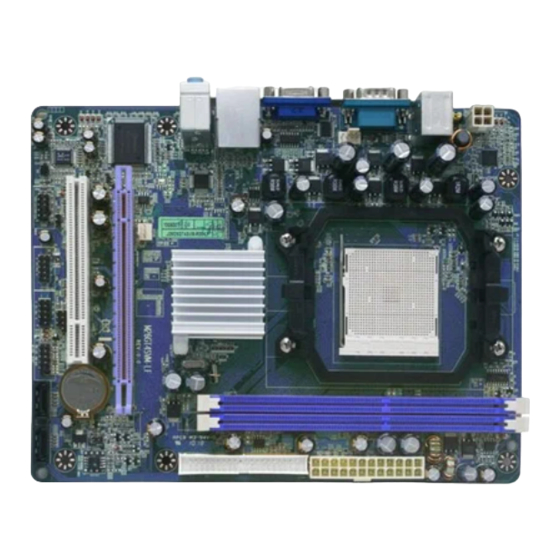
Layout Diagram RJ-45 LAN Line-IN PS/2 Mouse COM Port Line-OUT VGA Connector PS/2 Keyboard MIC-IN USB Connectors ATX 12V Power Connector DDRIII Slot x 2 PS2 KB/ Mouse Port Serial Port CPU Socket ATX Power Conn. CPUFAN1 VGA Connector RJ45 Over ATA 133 IDE USB Connector Conn. -
Page 8: Chapter 2 Hardware Installation
Chapter 2 Hardware Installation WARNING! Turn off your power when adding or removing expansion cards or other system components. Failure to do so may cause severe damage to both your motherboard and expansion cards. CPU Installation This motherboard provides a socket AM2 surface mount, Zero Insertion Force (ZIF) socket, referred to as the mPGA940 socket supports AMD AM3 processors. -
Page 9: Install Memory
Install Memory The motherboards provide two 240-pin DDRIII DUAL INLINE MEMORY MODULES (DIMM) sites for DDRIII memory expansion to maximum memory size of 8GB DDRIII SDRAM. Valid Memory Configurations Bank 240-Pin DIMM Maximum Capacity DIMM1 DDRIII 800/DDRIII 1066/DDRIII 1333 DIMM2 DDRIII 800/DDRIII 1066/DDRIII 1333 Total System Memory (Max.4GB) -
Page 10: Expansion Cards
Expansion Cards MCP61P series motherboards offer one PCI-Express x16by16-LANE graphics slot of 4Gbyte/sec data transfer rate at each relative direction which gets 3.5 times of bandwidth more than AGP8X and it’s up to a peak concurrent bandwidth of 8Gbyte/sec at full speed to guarantee the performance and compatibility of GPU graphics add-in cards. -
Page 11: Connectors
Chapter 3 Connectors, Headers & Jumper Setting 3-1 Connectors Power Connector (24-pin block): ATXPWR ATX Power Supply connector: This is a new defined 24-pins ROW1 ROW2 connector that usually comes ROW1 ROW2 ROW1 ROW2 3.3V 3.3V with ATX case. The ATX Power 3.3V -12V Supply allows using soft power... - Page 12 (2) ATX 12V Power Connector (4-pin block): ATX12V This is a new defined 4-pins connector that usually comes with ATX Power Supply. The ATX Power Supply which fully supports AMD AM3 processor must including this connector for support extra 12V voltage to maintain system power consumption.
- Page 13 (7) Primary IDE Connector (40-pin block): IDE1 This connector connects to the next set of Master and Slave hard disks. Follow the same procedure described for the primary IDE connector. You may also configure two hard disks to be both Masters using one ribbon cable on the primary IDE connector and another ribbon cable on the secondary IDE connector.
-
Page 14: Headers
3-2 Headers (1) Line-Out/MIC Header for Front Panel (9-pin): AUDIO These headers connect to Front Panel Line-out, MIC connector with cable. AUDIO Pin 1 Line-Out, MIC Headers (2) USB Port Headers (9-pin):USB1/USB3 These headers are used for connecting the additional USB port plug. By attaching an option USB cable, your can be provided with two additional USB plugs affixed to the back panel. - Page 15 PWRLED Pin 1 JW_ FP SPEAK Pin 1 Pin 1 System Case Connections (8) FAN Power Headers: SYSFAN1 (3-pin), CPUFAN1 (4-pin) These connectors support cooling fans of 350mA (4.2 Watts) or less, depending on the fan manufacturer, the wire and plug may be different. The red wire should be positive, while the black should be ground.
-
Page 16: Jumper Setting
3-3 Jumper Setting (1) Keyboard/USB function Enabled/Disabled: JP1 2-3 Closed KB/USB Pow er ON Enabled 1-2 Closed KB/USB Power ON Disable (Default) Keyboard/ USB Power On Setting (2) CMOS RAM Clear (2-pin): JBAT1 A battery must be used to retain the motherboard configuration in CMOS RAM, short 1-2 pins of JBAT to clear the CMOS data. -
Page 17: Chapter 4 Useful Help
Chapter 4 Useful Help 4-1 How to Update Bios Step 1. Prepare a boot disc. (You may make one by click START click RUN type SYS A: click OK) Step 2. Download upgrade tools and the latest BIOS files of the motherboard from official website and then make a copy of it to your bootable floppy disk after decompressing these files Step 3. -
Page 18: Appendix1
Appendix I Subject 1: Regarding the Application of 3-Phase or 3+1 Phase Power Supply Mold As a result of the increasing power consumption demand from many AMD CPUs in current market, we suggest not to use a CPU that demands more than 65W power consumption at work for an AMD CPU compliant board that comes with power supply design as 3 phase or 3+1 phase mold and MOSFET design as working in High SideX1 and Low SideX1 mold so as to avoid MOSFET getting... - Page 19 Solution: We recommend users choose motherboards with power design of 4-phase, 4+1 phase or more for CPUs that demand 89W or 95W power consumption. We recommend users choose motherboards with power design of 5-phase, 5+1 phase or more for CPUs that demand 125W or 140W power consumption. Subject 2: Suggestion on choosing electric fan Both the amount of electric current to MOSFET and the heat produced from the motherboard go up as AMD’s CPU power...
Need help?
Do you have a question about the M26GT4SVM and is the answer not in the manual?
Questions and answers