Table of Contents
Advertisement
Quick Links
Advertisement
Table of Contents

Related Manuals for Ablerex KRONOS


Summary of Contents for Ablerex KRONOS
- Page 1 KRONOS 208V 10-40kVAUPS Installation and Operation Manual...
-
Page 2: Table Of Contents
Auxiliary Power Supply Control Switch and Precharge Button ..... 39 Communication Cables Connections .............. 40 UPS Parallel Connections (Option) ..............44 3. Kronos Operation And Descriptions ..............48 Operating Mode....................48 Online Operations ................... 49 Manual Bypass Operation ................49 Operating Processes .................. -
Page 3: Preface
We thank you for the trust in selecting our Kronos UPS. The purpose of this manual is to introduce the user to the operating principles of the Kronos UPS and to provide instructions in it's safe operation. The manual also provides troubleshooting assistance should an abnormal message or behavior occur. -
Page 4: Safety
Important Rules (1) Please follow the Kronos UPS operating instructions to ensure safe and proper operation. (2) When the UPS is being moved or operated, please ensure that the machine is standing vertically. Do not shake or tip over the machine. Avoid heavy impact. - Page 5 - CAUTION: Do not open or mutilate batteries. Released electrolyte is harmful to the skin and eyes, and may be toxic. - CAUTION: A battery can present a risk of electrical shock and high short-circuit current through conductive materials could cause severe burns. The following precautions should Be observed when working on batteries: Before installing or replacing the batteries, remove jewelry such as wristwatches and rings, or other metal objects.
- Page 6 NOTE : This equipment has been tested and found to comply with the limits for a Class A digital device, pursuant to part 15 of the FCC Rules. These limits are designed to provide reasonable protection against harmful interference when the equipment is operated in a commercial environment.
-
Page 7: Function Description
Function Description 1.1 UPS Block Diagram The system block diagram is shown below. Dual Inputs ngle Input Bypass Input Mains Input Load Load Battery Battery ○ 1 ○ 5 Input Breaker/Switch Static Switch ○ 2 ○ 6 Manual Bypass Breaker Charger/Booster ○... -
Page 8: Ups Front View
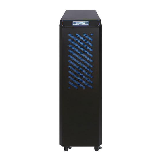
UPS Front View 10kVA Front View 260mm 69mm 1 Control Panel with Color LCD Touch Screen 3 Wheels for Positioning 2 Ventilation Grille... - Page 9 15-20kVA Front View 410mm 72mm 1 Control Panel with Color LCD Touch Screen 3 Wheels for Positioning 2 Ventilation Grille...
- Page 10 30-40kVA Front View ○ ○ ○ 1 Control Panel with Color LCD Touch Screen 3 Wheels for Positioning 2 Ventilation Grille...
- Page 11 10kVA Right Side View 850mm...
- Page 12 15-20kVA Right Side View 850mm...
- Page 13 30-40kVA Right Side View ...
- Page 14 10kVA Rear View 1. Communication Slot 1 2. Communication Slot2 3. Dry Contacts 4. External Battery Temperature Connector 5. RS-232 Port for Setting Software 6. Parallel Communication Ports(Option) 7. Communication Selector for Service Only 8. USB Port for Service Only 9.
- Page 15 15-20kVA Rear View 1. Communication Slot 1 2. Communication Slot2 3. Dry Contacts 4. External Battery Temperature Connector 5. RS-232 Port for Setting Software 6. Parallel Communication Ports(Option) 7. Communication Selector for Service Only 8. USB Port for Service Only 9.
- Page 16 30-40kVA Rear View 1. Communication Slot 1 2. Communication Slot2 3. Dry Contacts 4. External Battery Temperature Connector 5. RS-232 Port for Setting Software 6. Parallel Communication Ports(Option) 10 11 7. Communication Selector for Service Only 8. USB Port for Service Only 9.
- Page 17 10kVA Internal Right View Battery Tray...
- Page 18 15-20kVA Internal Right View Battery Tray...
- Page 19 10kVA Internal Top View ○ ○ Jumpers (J1~J3) for each output SD Card Slot contact The detailed descriptions of the above items are located in section 2-6.
- Page 20 15-20kVA Internal Top View ○ ○ Jumpers (J1~J3) for each output SD Card Slot contact The detailed descriptions of the above items are located in section 2-6.
- Page 21 30-40kVA Internal Top View ○ ○ Jumpers (J1~J3) for each output SD Card Slot contact Please find the detail descriptions of above items on section 2-6.
-
Page 22: Installation And Wiring
Installation and Wiring 2.1 Storage and Installation Environment Storage Environment Temperature-20℃~70℃ Relative Humidity≦95% Installation Environment A proper installation environment not only ensures the effective operation of the UPS but it also reduces the chance of failure and extends service life. Take the following recommendations into account when selecting a suitable environment. -
Page 23: Unpacking, Removing And Securing Ups
Unpacking, Removing and Securing UPS This section describes the unpacking and removing processes with the wheels installed. Remove the packing materials and cut straps. Remove and slide up the cardboard box. 10kVA 15-20kVA 30-40kVA Unscrew the fasteners on the ramp kits located on the right and left side of 10kVA, as well at the front side of 15-40kVA. - Page 24 15-20kVA 30-40kVA...
- Page 25 Install 2 fasteners on the rail kits on the pallet edge by fastening 4 screws in the pallet. 10kVA Remove the UPS from the pallet by using the rails to slide the UPS forward onto a flat surface. See the next figure when using a Fork Lift to remove the UPS from the pallet. 10kVA...
- Page 26 15-20kVA 30-40kVA...
- Page 27 Raise the wheel-brakes to remove the UPS. Wheel-Brake 10kVA Wheel-Brake 15-20kVA...
- Page 28 Wheel-Brake 30-40kVA Block the wheel-brakes to secure the UPS. Wheel-Brake 10kVA...
- Page 29 Wheel-Brake 15-20kVA Wheel-Brake 30-40kVA...
- Page 30 Follow this step to secure the UPS. 10kVA 15-20kVA...
- Page 31 30-40kVA...
-
Page 32: General Requirements For Ventilation And Maintenance
General Requirements for Ventilation and Maintenance During the installation ensure that the following conditions are followed. Keep at least 1000mm of clearance to the front of the UPS for air flow and future maintenance purposes. Keep at least 300mm of clearance from the rear of the UPS for air-flow space. ... -
Page 33: Power Cables Connections
Power Cables Connections Power Connection Positions The drawing below shows the positions of the power terminals. Bypass Grounding Grounding Mains Output Battery 10kVA Power Terminal Positions Grounding Grounding Mains Bypass Output Battery 15-20kVA Power Terminal Positions... - Page 34 Battery Grounding Mains Bypass Output Grounding 30-40kVA Power Terminal Positions Maximum Current Table Max. Input/ Output Maximum Input Max. Battery Output Power Output/Bypass Input Voltage Current Discharge Current Current 10kVA/10kW 33.8A 28.9A 70.4A 15kVA/15kW 50.2A 43.3A 105.0A 200V 20kVA/20kW 67.2A 57.7A 140.0A...
- Page 35 Minimum Recommended Size of Cables Mains Input Output/Bypass Input External Battery Capacity R/S/T/N/PE R/S/T/N/PE B+/N/B-/PE 10kVA 10 AWG / 6mm 10 AWG / 6mm 6AWG / 16 mm TQ:22.1 Lb-in TQ:22.1 Lb-in TQ:53.1 Lb-in 15kVA 8 AWG / 10 mm 8 AWG / 10 mm 2 AWG / 35 mm TQ:22.1 Lb-in...
- Page 36 Electrical System Connections UPS with single input Load 3P+N UPS with single input and isolation transformer Load 3P+N...
- Page 37 UPS with dual inputs 3P+N Load 3P+N UPS with dual inputs and isolation transformer 3P+N Load 3P+N 3P+N Load 3P+N...
- Page 38 3P+N Load 3P+N Note : You must install an isolation transformer on one of the inputs if the two power source are different. UPS in parallel, using separate battery Load 3P+N...
- Page 39 UPS in parallel, using a common battery Load 3P+N...
- Page 40 UPS in parallel with an output transformer Do not use individual output transformers for each UPS. A common output transformer must be used. Load 3P+N Load 3P+N...
-
Page 41: Auxiliary Power Supply Control Switch And Precharge Button
Auxiliary Power Supply Control Switch and Precharge Button 10kVA 15-20kVA 30-40kVA AC Power This is auxiliary power switch for the main control power. This Power switch is used first in sequence before turning on UPS. Don't switch this OFF at any time while the UPS is operating. -
Page 42: Communication Cables Connections
Communication Cables Connections 10kVA 15-20kVA 30-40kVA Dry Contacts The UPS provides 3 output dry contacts and1 input contact. Specification of Output dry contact:250 VAC/ 2 A; 30 VDC/2 A There are 3 jumpers (J1~J3) to set NC/NO for each output contact. To short the input contact to send a command to the UPS. - Page 43 Default Definition General alarm OUT-1 Load on inverter OUT-2 Load on Bypass OUT-3 Normal mode Communication Slot1 This slot can will accept a Relay card or RS-485 MODBUS card. Communication Slot2 This slot will accept a Relay card or SNMP card. Always ensure that the SW2 switch is in the correct position when this slot is used.
- Page 44 USB This port is for service only. Switch—the switch for a terminal resistor for parallel communication To ensure good parallel communication quality, please set the switch of the two farthest UPS to the “ON” position. Please refer to section 2-7 for detail. ...
- Page 45 SW2 When the Relay Card is installed in Slot 2, move the switch to “Slot” position. When SNMP card is installed in Slot 2, move the switch to “SNMP” position. SW3--the switch for terminal resistor of parallel communication To ensure a proper parallel communication connection, the selector switch on each of the additional UPSs', starting from the furthest UPS, must be moved to the “ON”...
-
Page 46: Ups Parallel Connections (Option)
UPS Parallel Connections (Option) The Kronos UPS may be operated in parallel to increase it's capacity and also adds redundantcy and increases the systems reliability. Up to 6 UPS units may be connected and operated in parallel. Each UPS requires the additional of the parallel card (Option). - Page 47 Parallel communication cables connected are shown below.
- Page 48 Recommended 1+1 parallel system configuration Mains Bypass Parallel Communication Cables Load 1+1 parallel...
- Page 49 Recommended N+1 parallel system configuration Mains Bypass Parallel Communication External Up to 6 UPS Units Cables Manual Bypass Switch Load...
-
Page 50: Kronos Operation And Descriptions
3. Kronos Operation And Descriptions 3.1 Operating Mode The UPS provides the following operating modes: Normal Mode(Online Mode) In Normal mode, grid power is passed through Rectifier then used to charge the battery and provide power through the Inverter simultaneously. Different output voltages settings can be set in VFI mode. -
Page 51: Online Operations
3.2 Online Operations The Kronos online UPS provides stable power that is not affected by an unstable main power supply (eg. grid power). Through the Kronos online UPS, the power provided is a clean, noise- free power source. The online architecture offers three types of power supply methods depending on the power environment. -
Page 52: Operating Processes
3.4 Operating Processes 10kVA 15-20kVA 30-40kVA... - Page 53 3.4.1 Normal Mode Start-up (1) On the rear of UPS, switch ON the AC Power switch. (2) Close UPS Mains Input Breaker/Switch and Bypass Input Breaker if equipped. (3) Select →Command→Operation→Normal Mode on LCD display. (4) Return to the Mimic Display. Wait for few minutes, the rectifier will have started. (5) Close the battery switch/fuses to connect the batteries after rectifier has been turned on.
- Page 54 (6) The inverter will have started and supply output voltage. (7) Close the UPS Output Breaker to supply the power to the load. 3.4.2 Cold Start User can start-up the UPS using the battery when main input power is not available. If the UPS is with an external battery configuration, it is imperative that the batteries are connected.
- Page 55 3.4.4 Switch to bypass Select →Command→Operation→Loadon Bypasson LCD display. The Inverter will be shutdown and the bypass will supply the power to the load. If the battery is disconnected, Rectifier and Charger will be shutdown as well. 3.4.5 Switch from normal mode to maintenance bypass Select →Command→Operation→Loadon Bypass on LCD display.
-
Page 56: Control Panel Operation And Function Description
4. Control Panel Operation and Function Description Each Kronos UPS is equipped with an LCD touch panel to provide the user with a simple and intuitive user interface that is easy to learn. The touch panel offers a combination of graphics and numbers that make it easy to determine the input/output voltage, frequency, load and battery level at a glance. -
Page 57: Menu
4.2 Menu Click to enter to the Menu screen as shown in above picture. Slide the screen to select the menu page and click the menu icon to enter to the desire function. Click to hide/show the sub-menu. The button below will appear on some of the function pages. Button Function Click it to save the new setting... - Page 58 All menu functions are in the table below. Menu Sub-Menu Functions Displays the UPS status、alarm、operating mode and Mimic Display measurements. Please refer to section 4-3 for more detail. Normal Mode ECO Mode Converter Mode Operation Shutdown ...
- Page 59 Menu Sub-Menu Functions Schedule Displays the schedule. Schedule Setting To define the schedule for ECO mode. Management Battery Test To define the schedule for battery test. Schedule Language Select the display language Update Prog. Upgrade the software of LCD touch display. General Set the turn off time of LCD backlight.
- Page 60 Enter in the Parameters Page From the menu, enter in the Setting Icon then tap the blue row to see additional Parameters Use the login password (Default is: 3366) then press enter You will not be able to modify the UPS parameters. Make sure that the converters are off in order to save them.
- Page 61 The UPS parameters that can be modified by the user using the control panel are listed in the table below. Parameters Content Range Default Independent/Common Ind. / Common Common Total cell number 96 ~ 120 Capacity 1~1000 Voltage Temperature compensation Yes / No Detect the Battery connecting Yes / No...
-
Page 62: Mimic Display
4.3 Mimic Display 【A】is Rectifier、【B】is Static Switch and 【C】is Inverter. The faded pattern indicates this part isn’t activated. The blue pattern indicates this part is activated. The red pattern indicates this part is currently in an abnormal condition. 【D】Displays the bypass input measurements. 【E】Displays the mains input measurements. -
Page 63: Options
5. Options 5.1 Dry Contact Card This card provides six output dry contacts and six input contact. These contacts are programmable and user can change the definition for each contact. Please refer to Dry Contact Card manual for more detail. 5.2 RS-485 MODBUS Card RS-485 ports with JBUS/MODBUS protocol. -
Page 64: Temperature Sensor
5.4 Temperature Sensor 3000.0±50mm 7±1mm Φ4.25±0.2 mm Measure the battery temperature. 5.5 Parallel Communication Card The parallel communication cards are required when 2 or more UPS are in parallel. Also included is a 1.5 meter parallel communication cable. A longer parallel communication cable is available when multiple UPS are in parallel. -
Page 65: Troubleshooting
6. Troubleshooting In the event of failure, the display area on the control panel will highlight the problem area in red. The “Alarm” symbol will also blink to warn that there is a problem with the UPS. Click to have an alarm list as below picture. We recommend using the following method when troubleshooting to export the event log and machine information from LCD panel to the SD card. -
Page 66: Exporting The Event Log From Lcd Panel
6-2. Exporting The event log from LCD panel 1. Make sure the SD card has been inserted on the LCD panel. 2. On the LCD, select →Event Log. 3. Before exporting, you need to refresh the log on LCD. Touch here for refreshing. 4. -
Page 67: Technical Specifications
7. Technical Specifications Capacity 10kVA 15kVA 20 kVA 30kVA 40kVA Input Voltage 208V 3 Phase + N ±20% @100% load, -40% ~-20% @50% load Voltage Tolerance Output capacity decrease linearly according to the input voltage Frequency 40 ~ 70Hz ≧ 0.99 Power Factor THDi ≦3% @ 100% load... - Page 68 Capacity 10kVA 15kVA 20 kVA 30kVA 40kVA HMI & Communication Display and 4.3" Colorful LCD Touch Screen Built-in Communication RS-232, EPO, Dry Contacts Port Optional 2 Communication Slots for SNMP Card, RS-485 MODBUS Card, Dry Contact Card Communication Mechanical Characteristic Dimensions (W x D x H) 260 x 850 x 890...
-
Page 69: Appendix
Appendix No. and type of battery Battery Case Battery Manufacturer Rating Flame Rating NPW45-12 12Vdc, 7.5Ah TAIWAN YUASA BATTERY CO., LTD. (MH28947) NPW45-12FR 12Vdc, 7.5Ah V- 0 NPW36-12 12Vdc, 7.0Ah NPW36-12FR 12Vdc, 7.0Ah V- 0 NP7.2-12 12Vdc, 7.0Ah NP7.2-12FR 12Vdc, 7.0Ah V- 0 DJW12-5.0 12Vdc, 5.0Ah... - Page 70 Battery Case Battery Manufacturer Rating Flame Rating HRL 1234W FR 12Vdc, 8.5Ah V- 0 HITACHI CHEMICAL ENERGY TECHNOLOGY CO LTD (MH14533) HRL 1223W 12Vdc, 5.75Ah HRL 1223W FR 12Vdc, 5.75Ah V- 0 HRL 1225W 12Vdc, 25W HRL 1225W F2 12Vdc, 25W HRL 1225W FR 12Vdc, 25W V- 0...
- Page 72 192321272020003...
Need help?
Do you have a question about the KRONOS and is the answer not in the manual?
Questions and answers