Table of Contents
Advertisement
Table of Content
3.6 VR Calibration and Setting Procedure
Chapter 4:
MS1K Troubleshooting Guide
4.6 Main Switch off, the Fan Still Working When
Utility Is Removed
4.7. Quick Trouble Shooting Guide
Chapter 5:
MS2K Troubleshooting Guide
5.6.Main Switch off, the Fan Still Working When
Utility Is Removed
5.7. Quick Trouble Shooting Guide
Chapter 6:
MS3K Troubleshooting Guide
6.6.Main Switch off ,Remove Utility, the Fan is still Working
6.7.Quick trouble shooting
1
Page
2
4
4
4
5
6
7
7
8
8
9
9
9
10
10
10
11
13
14
16
17
18
19
20
21
22
24
25
26
27
28
29
30
32
33
34
35
36
37
41
Advertisement
Table of Contents

Related Manuals for Ablerex 3 MS series


Summary of Contents for Ablerex 3 MS series
-
Page 1: Table Of Contents
Table of Content Page Chapter 1: General Introduction Guide 1.1. General Introduction 1.2. System Layout and Description 1.2.1.Front Panel and Rear Panel Layout 1.2.1.1. Front Display Panel Explanation 1.2.1.2. Rear Panel Explanation 1.3. Communication Port Explanation Chapter 2: System Block Diagram 2.1. -
Page 2: Chapter 1: General Introduction Guide
Chapter One: General Introduction Guide 1.1. General Introduction The Smart Mars MS high frequency on-line UPS series, adopting 50KHz High-frequency topology and integrating with micro-processor based central Control circuit and smart RS232 communication, offers extremely high industrial Grade protection, user-friendly interface for a wide range of application. 1.1.1. - Page 3 1.1.2. The Advanced Technical Characteristics l Market leading light and compact design for modern OA environment and OEM flexibility. l Powerful CPU integrates all power stages, control and communication functions necessary for maximized UPS protection and functionality, including Power management status monitoring, configuration setting operation Scheduling, remote control and self-diagnosis.
-
Page 4: System Layout And Description
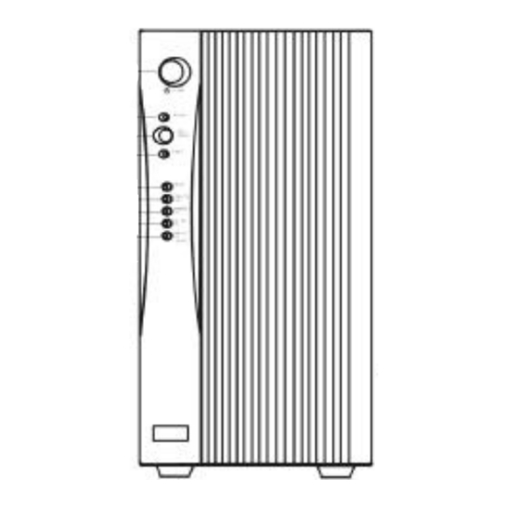
1.2 . System Layout and Description 1.2.1. Front Panel and Rear Panel Layout 1.2.1.1. Front Panel Explanation Main Switch This is control the on/off of the UPS Self Test OK LED Green LED lights up if self test is O.K. Test/Silence a. -
Page 5: Rear Panel Explanation
1.2.1.2. Rear Panel Explanation 1KVA 2KVA 3KVA RACK 1KVA RACK 2KVA RACK 3KVA 1) AC Inlet This is to be connected with an AC power cord for plugging into the wall receptacle. 2) AC Input This is to disconnect line input to protect application from Output Fuse overload or short circuit. -
Page 6: Communication Port Explanation
Local Sockets 1pce 2pcs 2pcs Terminal Block N/A Terminal AC Outlet Socket Type MS1K/ MS2K MS2KR MS3K/MS3KR (for120Vac) MS1KR NEMA5-15R 4pcs 4pcs 2pcs NEMA5-20R 1pce 1pce NEMA5-30R 1pce Terminal Block N/A 5) SNMP Slot It is an optional feature used for SNMP card. 6) Comm Port This is an interface to send signals to and receive signals from the computer. - Page 7 Pin 6: RS232 Rx Pin 9: RS232 Tx Pin 7: Ground...
-
Page 8: Chapter 2: System Block Diagram
Chapter Two: System Block Diagram Basically, the Mars MS series are composed of Logic Board, Driver Board, And Display Board. 2.1. PC Boards and Their Functions Explanation The Mars MS series is composed of three major boards, of which functions are Explained as follows: Item Board Part No. -
Page 9: Driver Board Block Diagram
2.3. Driver Board Block Diagram The circuitry of Driver Board can mainly divided into five sections. They are Charger circuit, UPS System Source Circuit, Input Power Factor Correction Circuit, DC to AC Converter Circuit and DC Booster circuit. A block diagram is illustrated as follows: 2.4. -
Page 10: Chapter 3: Field Calibration Guide
Chapter Three: Field Calibration Guide 3.1. Introduction There are several variable resistors(SVR or potential-meter) and jumpers on the PCB. They are used for the adjustments of set points which vary from different electrical applications. 3.2.Tools Required Tools Description 1. AC Source : To offer an input power 100/110/120 or 220/230/240Vac to the UPS. -
Page 11: Test Point Default Value
3.4. Test Point Default Value a. Control Logic Board: MS-I9919-x Jumper Functions Reserved Reserved Output Voltage Calibration JP4(Default: Open for Internal Charger) Internal/External Charger Selection Reserved Driver Board: 1K(MS9917- 2K(MSBD- MS3K(MSCD- Functions Manual PFC Start-on Switch Over-temperature Protection Manual DC Booster Switch 3.5. -
Page 12: Vr Calibration And Switch Setting Procedure
3.7 VR Calibration and Switch Setting Procedure 3.7.1 VR/Switch Function Explanation 3.7.1.1 VR Function Explanation MS1K(R)/2K(R)/3K(R) Adjustment A. Logic Board: MS-I9919-x O/P Voltage Balance Output Voltage Selection CPU Reset B. Driver Board: MSD9917-x or MSADxxx for 1K; MSD9910-x or MSBDxxx for 2K; MSCDxxx for MS3K Charger Output Voltage 3.7.2. - Page 13 3.7.2.2. Setting Procedure for EARLY version of CPU ( MS01013F¡BMS03014B and those before MS0731) 1. Short the JP3 of the control board by jumper cap. Do Not Connect Battery. 2. Add 110V/60Hz or 220V/50Hz and Adjust Charger Voltage: 41.4V for MS1K/MS1KR, 82.8V for MS2K/MS2KR and 110.4V for MS3K/MS3KR.
- Page 14 3.7.2.3. Setting Procedure for NEW version of CPU 1.Short the JP3 of the control board by jumper cap. Do Not Connect Battery. 2.Add 110V/60Hz or 220V/50Hz and Adjust Charger Voltage: 41.4V for MS1K/MS1KR, 82.8V for MS2K/MS2KR and 110.4V for MS3K/MS3KR. (Important: The input voltage must be precisely110V/60Hz or 220V/50Hz) 3.Software Setting(This part is not nessary if the UPS already been set)¡C 4.Switch on the front switch of the UPS and adjust the output voltage to...
-
Page 15: Utility Is Normal, But Ups On Battery Mode
Chapter Four: Trouble Shooting Guide For MS1K 4.1. Utility is Normal, but UPS on Battery Mode FIG. 4.1 Check Items Trouble-shooting Utility Voltage is out of windows(<80Vac or Your Utility quality is too bad. You are >140Vac for 120Vac system;160Vac or >280Vac recommended to install an AVR in front of the for 230Vac system) UPS. -
Page 16: Fault Led Lights Up And No Output
4.2. Fault LED Lights up and No Output 4.2.1. Troubleshooting FIG. 4.2 Check Items Trouble-shooting Output Short Circuit Check if the output end of the UPS is in short circuit. Overload(>120%) Reduce the output load. MS1K/MS1KR: 1000VA/700W Battery voltage is abnormal 1. - Page 17 2. Connect 12Vdc t o the Fan(red line to positive) to check if the fan is normal. 3. Otherwise, please check the related circuit as fig 4-2. Environmental Temperature is out of Improve the ventilation and reduce the temperature of the windows( environment.
-
Page 18: Input Fuse Is Burnt
4.3. Input Fuse is burnt FIG. 4.3 Check Items Trouble-shooting The IGBT of Inverter Stage is out of order 1. Check the related circuit as shown in fig.4-4. Check Q14, Q13, D24, D25, R118 and R120 are defective. If Q14¡BQ13 is abnormal, U7,U8 need to be replaced, too. -
Page 19: Ups Fails To Backup When Blackout
4.4. UPS Fails to Backup When Blackout FIG. 4.4 Check Items Trouble-shooting Battery is weak and no Remove the harness of the battery from the control board to measure the battery battery charging urrent voltage. If the voltage drops dramatically, please use a switching power supply When it is in charging to charge the battery. -
Page 20: No Leds And No Output
4.5. No LEDs and No Output FIG. 4.5 Check Items Trouble-shooting Power Devices defective, AC or DC fuse is burn Please see table 4.3 and 4.4 . The working voltage of the control board is out 1. Please check the circuit shown in fig.4-2. of order. - Page 21 4.6. Main Switch Off, Remove Utility, the Fan is Still Working. Check Items Trouble-shooting Self-Keeping Circuit is out of order 1. Please check the related circuit as shown in 4-2. 2. Cut off the Utility, turn off the front switch then remove and re-connect the harness of the battery to see whether the fan still remains spinning.
- Page 22 4.7 Quick trouble shooting UPS MALFUNCTION PFC fault AC fuse is burn 1. Replace Q12, U6 2. check BD1, D19 Q12 short and R116 Q13,Q14 INVERTER fault short 1.replace Q13, Q14, U7, U8 2.Check R118 R120, DC fuse is burn D24 and D25 Booster fault.
-
Page 23: Utility Is Normal, But Ups On Battery Mode
Chapter Five: Trouble Shooting Guide For MS2K 5.1. Utility is Normal, but UPS on Battery Mode FIG. 5.1 Check Items Trouble-shooting Utility Voltage is out of windows(<80Vac or Your Utility quality is too bad. You are >140Vac for 120Vac system or <160Vac or recommended to install an AVR in front of the >280Vac for 230Vac system) UPS. -
Page 24: Fault Led Lights Up And No Output
Fault LED Lights up and No Output FIG. 5.2... - Page 25 5.2.1. Troubleshooting Check Items Trouble-shooting Output Short Circuit Check if the output end of the UPS is in short circuit. Overload(>120%) Reduce the output load to 2000VA/1400W Battery voltage is abnormal If the battery voltage is under 59V, replace the batteries¡C Remove the battery, and check the charge voltage.
-
Page 26: Input Fuse Is Burnt
5.3 Input Fuse is burnt FIG. 5.3 Check Items Trouble-shooting The IGBT of Inverter Stage is out of order 1.Check the related circuit as shown in fig.5-4. Check Q6, Q7, D12, D13, R83 and R104 are defective. If Q6&Q7 are abnormal, the U6 & U7 need to be replaced, too. -
Page 27: Ups Fails To Backup When Blackout
5.4 UPS Fails to Backup When Blackout FIG. 5.4 Check Items Trouble-shooting Battery is weak and no battery Remove the harness of the battery from the charging current control board to measure the battery voltage. If When it is in charging mode. the voltage drops dramatically, please use a switching power supply to charge the battery. -
Page 28: No Leds And No Output
5.5 No LEDs and No Output FIG. 5.5 Check Items Trouble-shooting Power Devices defective, AC or DC fuse is burn Please see table 5.3 and 5.4 . The working voltage of the control board is out 1.Please check the circuit shown in fig.5-2. of order. - Page 29 5.6 Main Switch Off, Remove Utility, the Fan is Still Working. Check Items Trouble-shooting Self-Keeping Circuit is out of order 1.Please check the related circuit as shown in 5-2. 2.Cut off the Utility, turn off the front switch then remove and re-connect the harness of the battery to see whether the fan still remains spinning.
- Page 30 5.7 Quick trouble shooting UPS MALFUNCTION PFC fault AC fuse is burnt 1. Replace Q1, U3 2. check BD1, D11 Q1 short and R42 Q6,Q7 INVERTER short fault 1.replace Q6, Q7, U6, U7 DC fuse is burnt 2.Check R83 R104, Booster fault.
-
Page 31: Utility Is Normal, Butups On Battery Mode
Chapter Six: Trouble Shooting Guide For MS3K 6.1. Utility is Normal, but UPS on Battery Mode FIG. 6.1 Check Items Trouble-shooting Utility Voltage is out of windows(<80Vac or Your Utility quality is too bad. You are >140Vac for 120Vac system or <160Vac or recommended to install an AVR in front of the >280Vac for 230Vac system) UPS. -
Page 32: Fault Led Lights Up And No Output
6.2 Fault LED Lights up and No Output FIG. 6.2... - Page 33 6.2.1. Troubleshooting Check Items Trouble-shooting Output Short Circuit Check if the output end of the UPS is in short circuit. Overload(>120%) Reduce the output load to 3000VA/2100W Battery voltage is abnormal If the battery voltage is under 78V, replace the batteries¡C Remove the battery, and check the charge voltage.
-
Page 34: Input Fuse Is Burnt
6.3 Input Fuse is burnt FIG. 6.3 Check Items Trouble-shooting The IGBT of Inverter Stage is out of order 1. Check the related circuit as shown in fig.6-4. Check Q29-Q32, D15, D16, R159, R163, R169 and R172 are defective. If Q29-Q32 are abnormal, the U8 &... -
Page 35: Ups Fails To Backup When Blackout
6.4 UPS Fails to Backup When Blackout FIG. 6.4 Check Items Trouble-shooting Battery is weak and no battery Remove the harness of the battery from the charging current control board to measure the battery voltage. If When it is in charging mode. the voltage drops dramatically, please use a switching power supply to charge the battery. -
Page 36: No Led And No Output
3.Check if the U7 SG3525 is out of order. 4.Check if the Booster Transformer T2¡BT3 is open. 5.After replace the defective devices. To make sure the other parts of the UPS is OK. Disconnect the logic board from driver board. Cut off the Utility. - Page 37 Check Items Trouble-shooting Power Devices defective, AC or DC fuse is burn Please see table 5.3 and 5.4 . The working voltage of the control board is out 1.Please check the circuit shown in fig.6-2. of order. 2.Cut off the Utility. Remove the control board. Supply a 96Vdc to CN5(+) and CN6(-) by a DC Power supply, connect CN4 to the main switch.
- Page 38 6.7 Quick trouble shooting UPS MALFUNCTION PFC fault AC fuse is burnt 1.Replace Q5, U4 2.check BD1,BD2, Q5 short D9 and R47 Q29-Q32 INVERTER fault short 1.replace Q29-Q32, U8, 2.Check R159, R163, DC fuse is burnt R169, R172, D28-D31 Booster fault. 1.
-
Page 39: Appendix A.1.Wiring Diagram
Appendix a.1. Wiring Diagram a.1.1 For MS 1K... - Page 40 a.1.2. For MS 2K SNMP CARD Display Board Control Board RS-232 (Logic Board) MAIN SWITCH BAT+ Driver Board BATTERY BLOCK CN10 BAT- Blue Brown Brown Blue LINE External 200W Charger BOARD Board CASE OUTLET...
- Page 41 a.1.3. For MS3K...
-
Page 42: Placements
a.2. Placements a.2.1 For MS1K /220V... - Page 43 a.2.2 For MS2K/220V a.2.3. For MS3K...
- Page 44 a.2.3 For MS3K/220V...
- Page 45 a.2.4 For MS1K/120V...
- Page 46 a.2.5 For MS2K/120V...
- Page 47 a.2.6For MS3K/120V file: smenu_ms.doc...
Need help?
Do you have a question about the 3 MS series and is the answer not in the manual?
Questions and answers