Table of Contents
Advertisement
Intelligent True On-Line UPS
For Corporate and IT Users
User Manual
1, 2, and 3 kVA
Table of Contents
1.
Safety and Storage Instructions ............................................................ 2
1.1. Safety .................................................................................................... 2
1.2. Storage.................................................................................................. 4
2.
Product Introduction .............................................................................. 5
2.1. General Characteristics......................................................................... 5
2.2. Special Features ................................................................................... 6
3.
UPS Functional Descriptions................................................................. 7
3.1. Front Panel Display ............................................................................... 7
3.2. Rear Panel ............................................................................................ 9
3.3. Operating Modes and System Voltage Configurations........................ 10
3.4. Communication Port Explanation ........................................................ 11
4.
Installation and Operation ................................................................... 13
4.1. Unpacking ........................................................................................... 13
4.2. Selecting Installation Position.............................................................. 13
4.3. Operation ............................................................................................ 14
5.
UPS Operation Under Various Conditions .......................................... 16
5.1. UPS System Block Diagram................................................................ 16
5.2. When Utility is Normal ......................................................................... 17
5.3. When Utility is Abnormal or Absent..................................................... 18
5.4. Overload Condition.............................................................................. 19
5.5. Inverter Failure .................................................................................... 20
5.6. Overheating......................................................................................... 20
5.7. Inverter Current or Voltage Out of Tolerance ...................................... 20
6.
Maintenance Guide ............................................................................. 21
6.1. Troubleshooting................................................................................... 21
6.2. Error Codes and Their Meanings ........................................................ 24
6.3. Maintenance........................................................................................ 24
7.
Communication Software .................................................................... 25
7.1. Hardware Setup .................................................................................. 25
7.2. Software Installation ............................................................................ 25
8.
Optional Communication Cards .......................................................... 26
8.1. R2E (second RS-232) card ................................................................. 26
8.2. USE (USB) card .................................................................................. 26
8.3. DCE (Dry Contact) card ...................................................................... 27
8.4. SNMP Cards ....................................................................................... 28
9.
Specifications ...................................................................................... 30
1
Advertisement
Table of Contents

Subscribe to Our Youtube Channel
Related Manuals for Ablerex 1 kVA


Summary of Contents for Ablerex 1 kVA
-
Page 1: Table Of Contents
Table of Contents Safety and Storage Instructions ............2 1.1. Safety ....................2 1.2. Storage....................4 Product Introduction ................5 2.1. General Characteristics................. 5 2.2. Special Features ................... 6 UPS Functional Descriptions..............7 3.1. Front Panel Display ................7 3.2. Rear Panel .................... 9 3.3. -
Page 2: Safety And Storage Instructions
13. Ensure that the input voltage of the UPS matches the utility supply voltage. Safety and Storage Instructions Use a certified input power cable with the correct plugs and sockets for the system voltage. 1.1. Safety Do not open the case as there are no serviceable parts inside. Opening the case will void your warranty and introduces the risk of electric shock. -
Page 3: Storage
1.2. Storage Product Introduction If the UPS is unused for an extended period of time it must be stored in a 2.1. General Characteristics moderate climate. The batteries should be charged for 12 hours every three months by connecting the UPS to the utility supply and switching on the input 1. -
Page 4: Special Features
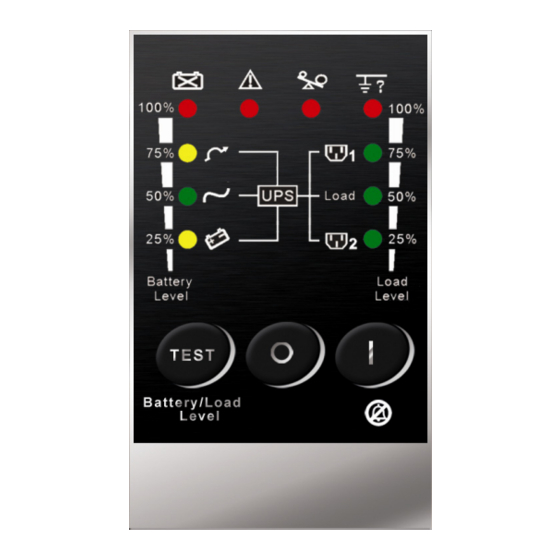
UPS Functional Descriptions 2.2. Special Features 3.1. Front Panel Display 3.1.1. LED Panel (Standard) 1. Our High Frequency Transformer-less technology and tower-convertible enclosure enables the UPS to be integrated into even the most difficult environments with space constraints. 2. This UPS is equipped with fully digital control logic for greater functionality and enhanced power protection. -
Page 5: Rear Panel
LED Indicator Symbol Description 3.2. Rear Panel 1. Solid indicates normal utility voltage. Blinking indicates insufficient utility voltage for the full load. 230V Normal Mode LED Off indicates abnormal utility voltage. 2. In Battery and Load Function Mode indicates battery capacity is 50%. 1. -
Page 6: Operating Modes And System Voltage Configurations
3.3. Operating Modes and System Voltage Configurations 3.4. Communication Port Explanation Download and open the “UPS Setting Tool” software to see the window below. The UPS is equipped with a true RS-232 communication port as standard to provide communication with bundled UPS monitoring software for remote monitoring of the UPS status using a PC. -
Page 7: Installation And Operation
Installation and Operation Pin Assignments: Please read the Safety Instruction guide (pages 2 and 3) before installing the UPS. 4.1. Unpacking Inspect the UPS upon receipt. The packaging is robust, but accidents and damage may still occur during shipment. Notify the forwarder and dealer if there is Pin 3: RS-232 Rx damage. -
Page 8: Operation
4.3. Operation 4.3.1.3 Shutdown 1. Shutdown in AC Mode 4.3.1. Using the standard LED panel Press and hold the OFF button ‘ ’ for five seconds until the buzzer beeps. 4.3.1.1 Start Up in Normal AC Mode The UPS will cut the power supply to the outlets. The ventilating fans will continue to operate. -
Page 9: Ups Operation Under Various Conditions
UPS Operation Under Various Conditions Utility Condition UPS Operating Mode LEDs Working power starts after approximately 5 seconds, LEDs on the 、 、 5.1. UPS System Block Diagram panel will blink and fans will start. Press Normal LEDs the ON button for 1-5 seconds. -
Page 10: When Utility Is Abnormal Or Absent
5.3. When Utility is Abnormal or Absent 5.4. Overload Condition The operating mode of the UPS under abnormal utility conditions is illustrated The operating mode of the UPS when overloading occurs is illustrated as as follows. follows. RECTIFIER STATIC SWITCH AC/DC CONVERTER INVERTER RECTIFIER... -
Page 11: Inverter Failure
5.5. Inverter Failure Maintenance Guide Output load short circuit when supplied via inverter 6.1. Troubleshooting If the output load is short-circuited while supplied via inverter, the UPS will shut down the inverter automatically and cut the supply to the loads. The Fault LED If the UPS malfunctions during operation please check that all lines are will shine, and the buzzer will beep continuously. - Page 12 Error Codes UPS fails to provide If the backup time remains battery backup or its unsatisfactory after 8 hours of When the Fault LED is lit press the ON button ‘ ’ briefly to check the backup time is shorter charging please contact your error code.
-
Page 13: Error Codes And Their Meanings
6.2. Error Codes and Their Meanings Communication Software 7.1. Hardware Setup Code Meaning Er05 Battery weak or faulty (For Decide whether to use RS-232 communication or USB communication. optional interface cards please refer to Chapter 8.) Er06 Output short-circuited 2. Connect a male RS-232 connector or a USB cable* to the UPS Er07 EPO mode communication port. -
Page 14: Optional Communication Cards
Optional Communication Cards 8.3. DCE (Dry Contact) card 8.1. R2E (second RS-232) card 8.3.1. Pin assignments of 10-Pin terminal: 8.1.1. CN1 is for RS-232 DB9. 8.1.2. For interface settings and pin assignments please refer to section 3.4.1. 8.1.3. Installation Position: Optional Slot UPS in Bypass mode (Bypass) Utility Normal (normally closed contact) 8.2. -
Page 15: Snmp Cards
8.4. SNMP Cards 8.4.3. USB The USB communication protocol definition is as below. 8.4.1. SNMP/Web card Complies with USB version 1.0, 1.5 Mbps. Complies with USB HID version 1.0. Pin Assignments: VCC (+5V) D- D+ Ground 8.4.1.1 For installation please refer to the user’s manual that came with the card. -
Page 16: Specifications
Line mode Specifications Efficiency Battery mode MODEL ITEM ECO mode Number of CAPACITY VA / W 1000 VA/700 W 2000 VA/1400 W 3000 VA/2100 W batteries 110/140/160-300 VAC (Based on load percentage Voltage Rating Battery type 12 V/7.2 Ah Sealed, non-spillage, maintenance-free, lead acid 0-25% / 25-50% / 50-100%) Rated Battery Frequency Rating... - Page 17 Interface Compatible Microsoft Windows series, Linux, etc. Platforms Safety IEC/EN 62040-1-1 IEC/EN 62040-2 class A, IEC/EN 61000-4-2/-3/-4/-5/-6/-8, Standards and IEC/EN 61000-2-2, IEC/EN 61000-3-2/-3 Certifications Markings * The UPS communication software may be downloaded from the Ablerex Web site at: http://www.ablerex.com.tw/tw/htm/support-sl.htm...
- Page 18 192321172001002...
Need help?
Do you have a question about the 1 kVA and is the answer not in the manual?
Questions and answers