Table of Contents
Advertisement
Quick Links
Advertisement
Table of Contents

Related Manuals for Ablerex KRONOS Series


Summary of Contents for Ablerex KRONOS Series
- Page 1 KRONOS Series 10-40 kVA UPS Installation and Operation Manual...
-
Page 2: Table Of Contents
CONTENTS Preface ........................... 2 Safety ..........................3 1. Function Description ....................4 UPS Block Diagram ..................4 UPS Outlook View ..................5 2. Installation and Wiring ..................12 Storage and Installation Environment ............14 Unpacking, Removing and Fixing UPS ............15 General Requirement for Ventilation and Maintenance ........ -
Page 3: Preface
Preface We thank you for the trust in selecting our UPS. Our equipment complies with the European Community directives for professional equipment and is authorize to use the CE marking. The purpose of this manual is to introduce the operating principles of the UPS and to provide instructions for its safe operation. -
Page 4: Safety
Safety Important Rules (1) Please follow these UPS operating instructions to ensure safe and proper operation. (2) When the UPS is being moved or operated, please ensure that the machine is standing vertically. Do not shake or tip over the machine. Avoid heavy impact. (3) Poor grounding will lead to unexpected current leakage. -
Page 5: Function Description
Function Description 1.1 UPS Block Diagram The system block diagram is shown as below. ○ ○ Input Switch Static Switch ○ ○ Manual Bypass Switch Charger/Booster ○ ○ Rectifier Output Switch ○ ○ Inverter Bypass Switch... -
Page 6: Ups Outlook View
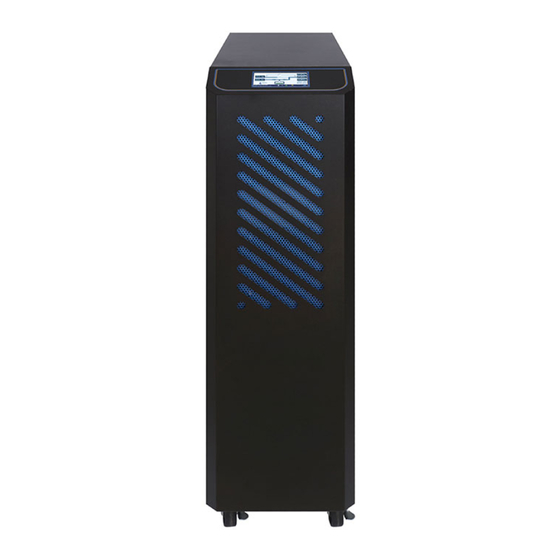
UPS Outlook View 10-20kVA Front View ○ ○ LCD Display Wheels for Handling ○ Ventilation Grille... - Page 7 30-40kVA Front View ○ ○ LCD Display Wheels for Handling ○ Ventilation Grille...
- Page 8 10-40kVA Right Side View...
- Page 9 10-20kVA Rear View (Single Input) ○ ○ ○ Communication Slot 1 ○ ○ Communication Slot2 ○ ○ ○ Dry Contacts ○ ○ External Battery Temperature Connector ○ ○ RS-232 Port for Setting Software ○ Parallel Communication Ports(Option) Communication Selector for ○...
- Page 10 10-20kVA Rear View (Dual Inputs) ○ ○ ○ Communication Slot 1 ○ ○ Communication Slot2 ○ ○ ○ Dry Contacts ○ ○ External Battery Temperature Connector ○ ○ RS-232 Port for Setting Software ○ Parallel Communication Ports(Option) Communication Selector for ○...
- Page 11 30-40kVA Rear View (Single Input) ○ ○ ○ Communication Slot 1 ○ ○ Communication Slot2 ○ ○ ○ Dry Contacts ○ External Battery Temperature Connector ○ ○ ○ RS-232 Port for Setting Software ○ Parallel Communication Ports(Option) ○ ○ ○...
- Page 12 30-40kVA Rear View (Dual Inputs) ○ ○ ○ Communication Slot 1 ○ ○ Communication Slot2 ○ ○ ○ Dry Contacts ○ External Battery Temperature Connector ○ ○ ○ RS-232 Port for Setting Software ○ Parallel Communication Ports(Option) ○ ○ ○...
- Page 13 10-20kVA Internal Right View ○ Battery Tray...
- Page 14 10-40kVA Internal Top View ○ Jumpers (J1~J3) for each output ○ contact Please find the detail descriptions of above items on section 2-6.
-
Page 15: Installation And Wiring
Installation and Wiring 2.1 Storage and Installation Environment Storage Environment Temperature-20℃~70℃ Relative Humidity≦95% Installation Environment A proper installation environment not only ensures the effective operation of the UPS but also reduces the chance of failure and extends service life. Please take the following recommendations into account to select the most suitable environment and reduce the likelihood of accidents. -
Page 16: Unpacking, Removing And Fixing Ups
Unpacking, Removing and Fixing UPS This section describes the unpacking and removing processes for wheel type. Remove the packing materials and cut straps. Remove the cardboard box. Unscrew the fastening rail kits on the right and left side. - Page 17 Put 2 fastening rail kits on the pallet edge and make them steady by fastening 4 screws in the pallet. Remove the UPS from the pallet.
- Page 18 Block the wheel-brakes to fix the UPS. Wheel-Brake Raise the wheel-brakes for remove the UPS.
- Page 19 As follow step to fix the UPS.
-
Page 20: General Requirement For Ventilation And Maintenance
General Requirement for Ventilation and Maintenance During installation ensure that the following conditions are met. Keep at least 1000 mm of free space in front of the UPS for air flow and future maintenance purposes. Keep at least 300mmof free space in rear of the UPS for air-flow space. ... -
Page 21: Power Cables Connections
Power Cables Connections Power Cable Sizing The drawing below shows the positions of power terminals. Single Input Dual Inputs (Option) 10-20kVA Power Terminal Positions Single Input Dual Inputs (Option) 30-40kVA Power Terminal Positions... - Page 22 Maximum Current Max. Maximum Max. Battery Input/Output Output/Bypass Output Power Input Discharge Voltage Input Current Current Current 10KVA/9KW 17.4 A 15.2 A 31 A 20KVA/18KW 34.4 A 30.4 A 62 A 380 V 30KVA/27KW 50.9 A 45.6 A 76 A 40KVA/36KW 67.7 A 60.8 A...
- Page 23 Recommended Circuit Breaker Size Input/Output Output Power Mains Input Output/Bypass Input Voltage 10KVA/9KW 20 A 20 A 20KVA/18KW 40 A 40 A 380 V 30KVA/27KW 63 A 50 A 40KVA/36KW 80 A 80 A 10KVA/9KW 20 A 16 A 20KVA/18KW 40 A 32 A...
- Page 24 Electrical System Connections UPS with single input UPS with single input and isolation transformer UPS with dual inputs (Option)
- Page 25 UPS with dual inputs and isolation transformer (Option) Note : You have to install an isolation transformer on one of the inputs if the two power system are different.
- Page 26 UPS in parallel, use separate battery UPS in parallel, use common battery...
- Page 27 UPS in parallel with output transformer Please do not use separate output transformer for each UPS. A common output transformer is recommended.
-
Page 28: Auxiliary Power Supply Control Switch And Button
Auxiliary Power Supply Control Switch and Button 10-20kVA 30-40kVA AC Power This is auxiliary power switch for the working power. Please ensure this Power switch is on before turn on UPS. Don’t switch off it when UPS is working. Batt. -
Page 29: Communication Cables Connections
Communication Cables Connections 10-20kVA 30-40kVA Dry Contacts The UPS provides 3 output dry contacts and1 input contact. Specification of Output dry contact : 250 VAC/ 2 A; 30 VDC/2 A There are 3 jumpers (J1~J3) to set NC/NO for each output contact. To short the input contact for send a command to UPS. - Page 30 Communication Slot2 This slot can install Relay card or SNMP card. Please ensure the SW2 switch to correct position when this slot is used. Batt. Temp.--External battery temperature connector Connect to external battery temperature sensor. Please refer to section 5-4. ...
- Page 31 EPO-- Emergence Power Off This EPO contact allows you to turn off the UPS in case of emergency. Short this contact to turn off the UPS immediately. Backfeed Trip The UPS provide a backfeed protection contact to trip the external electromechanical device for isolation from the power circuit.
-
Page 32: Ups Parallel Connections (Option)
UPS Parallel Connections (Option) The UPS can be operated in parallel for extend the capacity and enhances system reliability. Up to 6 UPS units can be operated in parallel. To make sure each UPS is equipped with parallel card (Option). ... - Page 33 When UPS operation in Parallel, please plug into parallel communication cables, as shown below.
- Page 34 mended 1+1 parallel system configuration Mains Bypass Parallel Communication Cables Load 1+1 parallel, Single Input 1+1 parallel, Dual Inputs(Option)
- Page 35 Recommended N+1 parallel for single input system configuration Parallel Communication Cables...
- Page 36 Recommended N+1 parallel for dual inputs system configuration Parallel Communication Cables...
-
Page 37: Operation Descriptions
3. Operation Descriptions 3.1 Operating Mode The UPS provides the following operating modes: Normal Mode(Online Mode) In Normal mode, grid power is passed through Rectifier then used to charge the battery and provide power through the Inverter simultaneously. Different output voltages settings can be set in VFI mode. -
Page 38: Online Operations
3.2 Online Operations An online UPS provides stable power that is not affected by an unstable main power supply (ex. grid power). Through the online UPS, grid power can provide a clean, noise- free power supply environment. The online architecture offers three types of power supply methods depending on the power environment. -
Page 39: Operation Processes
3.4 Operation Processes 10-20kVA 30-40kVA 3.4.1 Normal Mode Start-up (1) In the rear of UPS, switch ON the AC Power switch. (2) Close UPS Mains Input and Bypass Input Switches if equipped. (3) Hold down and then click on LCD display,and it will take you to the 【... - Page 40 (7) Close the battery switch/fuses to connect the batteries after rectifier has been turned (8) The inverter will be started and supply output voltage. (9) Close UPS Output Switch to supply the power to the load. 3.4.2 Cold Start (1) User can start-up UPS by battery when main input power is not available. (2) If the UPS with external batteries configuration, it must to make sure the batteries are connected.
- Page 41 (6) Press to selectMode Battery on and then press to excute the commad on LCD display. (7) Press to selectNormal Mode and then then press to start UPS on LCD display. (8) Once UPS working in Normal Mode, switch OFF the Batt. Power switch. 3.4.3 Shutdown (1) Hold down and then click...
- Page 42 Attention: IMMEDIATE LOAD OFF! For turn off the working power, switch OFF both AC Power and Batt. Power switches in the rear of UPS. 3.4.4 Switch to bypass (1) Push and then click on LCD display, and it will take you to the 【setting page】.
- Page 43 (3) Open/disconnected the external battery Switch/fuses if equipped. (4) Close the maintenance bypass switch. (5) Follow the processes in section 3.4.3 to shutdown UPS. (6) Open Output and Mains/Bypass Input switch. (7) In the rear of UPS, switch OFFAC Power and Batt. Power switches. 3.4.6 Maintenance bypass →...
- Page 44 3.4.8 Converter mode (CVCF) (1) Hold down and then click on LCD display, and it will take you to the 【setting page】. (2) Press to selectConvertermode and then press to excute the command on LCD display. It will display the existing setting of output frequency. Please use Setting Tool to change the frequency.
-
Page 45: Control Panel Operation And Function Description
4. Control Panel Operation and Function Description Each UPS is equipped with LCD control panel that includes LCD display, LED indicators and operation keypads to provide a simple user interface. User can have the real time input/output voltage, frequency, current and battery information and change UPS settings from the panel. -
Page 46: Led Indicators
LED Indicators LED Indicator Color Description Green Load on Inverter Yellow In backup mode Green Load on Bypass Green In ECO mode Represent the battery string positive voltage or R phase Green voltage or the number of battery cells. Green Represent S phase voltage or battery AH Represent battery string positive voltage or T phase Green... -
Page 47: Symbols On The Lcd Display Panel
Symbols on the LCD Display Panel Item Symbol Description Utility or Bypass Source. Battery Low. Battery Abnormal Battery is testing. UPS Overloading. UPS is working in maintenance mode. Bypass Input Abnormal, UPS fails to transfer to bypass, Bypass Abnormal at ECO mode. Utility Input Abnormal. -
Page 48: Alarm Code
Alarm code Item Symbol Description UPS Normal Abnormal communication with DSP. Parallel communication error. General alarm. General inverter alarm. General mains alarm General Discharger alarm. General Charger alarm. General Bypass alarm. Over temperature alarm. -
Page 49: Function Menu
4.7 Function Menu All menu functions are showing as below table. Main- Menu Sub-Menu Menu Functions Display the UPS input measurements. Utility Press to change the parameters. V=>A=>KVA=>KW=>Hz Display the UPS bypass measurements. Bypass Press to change the parameters. V=>A=>KVA=>KW=>Hz Display the UPS output measurements. - Page 50 Display the UPS in which mode. : Shutdown : Cold Start Recharge Ready Battery : Normal Mode UPS Mode : ECO Mode : Converter Mode Frequency : Load on Bypass Display parallel UPS in which mode. : Shutdown : Cold Start Recharge Ready Battery Parallel UPS : Normal Mode...
- Page 51 Press to select UPS command. : Shutdown : Cold Start Recharge Ready Battery Mode : Normal Mode : ECO Mode : Converter Mode Frequency Parallel : Load on Bypass Command Press to execute the command. Press to change buzzer setting. Buzzer : Enable buzzer.
- Page 52 Parallel ID Press to change the UPS ID. 1=>2…=>6 Press to confirm the setting. Parallel Setting Number of Parallel UPS Press to change the number of parallel UPS. 1=>2…=>6 Press to confirm the setting. Year Press to change the year setting. 19=>20…=>99 This means 2019,2020…2099.
-
Page 53: Options
5. Options 5.1 Dry Contact Card This card provides three output dry contacts and three input contact. These contacts are programmable and user can change the definition for each contact. Please refer to Dry Contact Card manual for more detail. 5.2 RS-485 MODBUS Card RS-485 ports with JBUS/MODBUS protocol. -
Page 54: Temperature Sensor
5.4 Temperature Sensor 3000.0mm 4.3mm 7.2mm Measure the battery temperature. 5.5 Parallel Communication Card The parallel communication cards are required when UPS in parallel and it comes with 1.5 meters parallel communication cable. A longer parallel communication cable is available for more UPS in parallel. -
Page 55: Technical Specification
6. Technical Specification Capacity 10 kVA 20 kVA 30 kVA 40 kVA Input Voltage 400V 3 Phase + N Voltage Tolerance ±20% @100% load, -40% ~-20% @50% load Frequency 40 ~ 70Hz Power Factor ≧ 0.99 THDi ≦3% Output Voltage 380/400/415V 3 Phase + N Voltage Tolerance ±1% (Static Load) - Page 56 Capacity 10 kVA 20 kVA 30 kVA 40 kVA HMI & Communication Display and MMI LCD Display Built-in RS-232, EPO, Dry Contacts Communication Port Optional Communication 2 Communication Slots for SNMP Card, RS-485 MODBUS Card, Dry Contact Card Mechanical Characteristic Dimensions 260 x 850 x 890 (Wheel type) (W x D x H) mm...
Need help?
Do you have a question about the KRONOS Series and is the answer not in the manual?
Questions and answers