Table of Contents
Advertisement
Advertisement
Table of Contents

Related Manuals for Ablerex TAURUS 10 kVA


Summary of Contents for Ablerex TAURUS 10 kVA
- Page 1 TAURUS Series 10-80 kVA UPS Installation and Operation Manual...
-
Page 2: Table Of Contents
CONTENTS Preface ..........................1 Safety ..........................2 Function Description ....................3 UPS Block Diagram ..................3 UPS Outlook View ..................4 Installation and Wiring..................15 Storage and Installation Environment ............15 Unpacking, Removing and Fixing UPS ............16 General Requirement for Ventilation and Maintenance ........ 23 Power Cables Connections ................ -
Page 3: Preface
Preface We thank you for the trust in selecting our UPS. Our equipment complies with the European Community directives for professional equipment and is authorize to use the CE marking. The purpose of this manual is to introduce the operating principles of the UPS and to provide instructions for its safe operation. -
Page 4: Safety
Safety Important Rules (1) Please follow these UPS operating instructions to ensure safe and proper operation. (2) When the UPS is being moved or operated, please ensure that the machine is standing vertically. Do not shake or tip over the machine. Avoid heavy impact. (3) Poor grounding will lead to unexpected current leakage. -
Page 5: Function Description
1. Function Description 1.1 UPS Block Diagram This UPS provides Mains input and Bypass input for dual inputs application. The system blockdiagram is shown as below. Bypass Input Mains Input Load Battery ○ ○ Input Switch Inverter ○ ○ Bypass Switch Static Switch ○... -
Page 6: Ups Outlook View
1.2 UPS Outlook View 10-40kVA Front View ○ ○ Control Panel with Colorful LCD Touch Screen Ventilation Grille ○ ○ Handle with Lock Wheels for Handling 192321262008007... - Page 7 10-20kVA Right Side View ○ Through Hole for Parallel Communication Cable 192321262008007...
- Page 8 10-20kVA Internal View ○ Parallel Communication Ports ○ HMICommunicationPort Communication Selector for ○ Service only ○ USB Port for Service Only Terminal Resistor Setting Switch ○ for Parallel Communication ○ Status LED Indictors ○ ○ Backfeed Protection ○ MBP Detector ○...
- Page 9 10-20kVA Rear View 10kVA 20kVA X50: Output Connections Terminal ○ X10/X40: Mains/Bypass Input (3N, 3L3, 3L2, 3L1) ○ Connections Terminal X20: External Battery Connections ○ (1N, 2N, 1L3, 2L3, 1L2, 2L2, 1L1, 2L1) Terminal(B+,N,B-) 192321262008007...
- Page 10 30-40kVA Right Side View ○ Through Hole for Parallel Communication Cable 192321262008007...
- Page 11 30-40kVA Interval View ○ Parallel Communication Ports ○ HMICommunicationPort Communication Selector for ○ Service Only ○ USB Port for Service Only Terminal Resistor Setting Switch ○ for Parallel Communication ○ Status LED Indictors ○ ○ Backfeed Protection ○ MBP Detector ○...
- Page 12 30-40kVA Rear View 30kVA 40kVA X50: Output Connections Terminal ○ X10/X40: Mains/Bypass Input (3N, 3L3, 3L2, 3L1) ○ Connections Terminal X20: External Battery Connections ○ (1N, 2N, 1L3, 2L3, 1L2, 2L2, 1L1, 2L1) Terminal(B+,N,B-) 192321262008007...
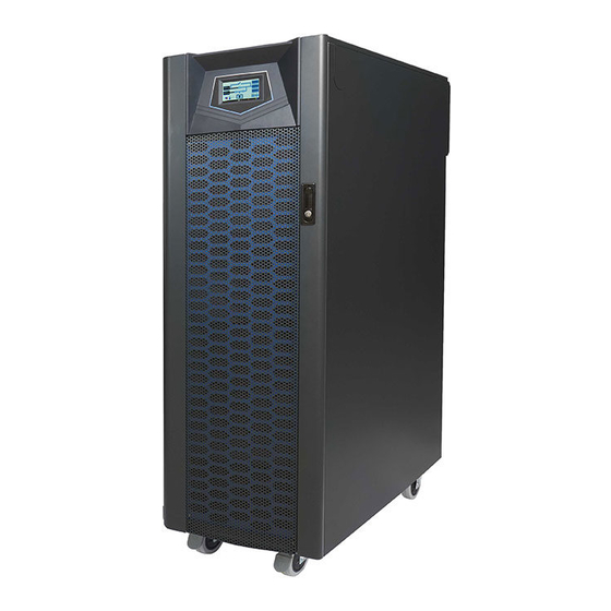
- Page 13 60-80kVA Front View Stationary Type Wheel Type (Without Wheel) ○ ○ Control Panel with Colorful LCD Touch Screen Ventilation Grille ○ ○ Handle with Lock Wheels for Handling 192321262008007...
- Page 14 60-80kVA Left Side View ○ ○ Stationary Type Wheel Type (Without Wheel) ○ Through Hole for Parallel Communication Cable 192321262008007...
- Page 15 60-80kVA Internal View Front Door ○ ○ ○ ○ ○ ○ ○ ○ ○ ○ ○ ○ Parallel Communication Ports ○ HMICommunicationPort Communication Selector for ○ Service Only ○ USB Port for Service Only Terminal Resistor Setting Switch ○ for Parallel Communication ○...
- Page 16 Rear Side of Front Door View ○ ○ ○ ○ ○ ○ ○ ○ USBPort for Setting Software Output &Input Contacts ○ ○ SD Card Slot RS-232 Port for Setting Software ○ ○ External Battery Temperature Connector CommunicationPort for Remote Panel Please find the detail descriptions of above items on section 2-5.
-
Page 17: Installation And Wiring
2. Installation and Wiring 2.1 Storage and Installation Environment Storage Environment Temperature-20℃~70℃ Relative Humidity≦95% Installation Environment A proper installation environment not only ensures the effective operation of the UPS but also reduces the chance of failure and extends service life. Please take the following recommendations into account to select the most suitable environment and reduce the likelihood of accidents. -
Page 18: Unpacking, Removing And Fixing Ups
Unpacking, Removing and Fixing UPS This section describes the unpacking and removing processes for wheel type. Remove the packing materials and cut straps. Remove the cardboard box. 10-40kVA 60-80kVA Unscrew the fasteningrail kits on the front and rear side of 10-40kVA, and right and left side of 60-80kVA. - Page 19 Put 2 fasteningrail kits on the pallet edge and make them steady by fastening 4 screws in the pallet. 10-40kVA 60-80kVA 192321262008007...
- Page 20 Raise 2 wheel-brakes or expansion foots for remove the UPS from the pallet. Wheel-Brake 10-40kVA Wheel-Brake 60-80kVA 192321262008007...
- Page 21 Block 2wheel-brakes or adjust the expansion foots to fix the UPS. Wheel-Brake 10-40kVA Wheel-Brake 60-80kVA 192321262008007...
- Page 22 Floor Fixing for 10-40kVA It is possible to reuse the fasteningrail kits to fix the UPS to the floor. 192321262008007...
- Page 23 Floor Fixing for 60-80kVA Stationary Type(Without Wheel) 192321262008007...
- Page 24 Floor Fixing for 60-80kVA Wheel Type It is possible to reuse the fasteningrail kits to fix the UPS to the floor. 192321262008007...
-
Page 25: General Requirement For Ventilation And Maintenance
General Requirement for Ventilation and Maintenance During installation ensure that the following conditions are met. Keep at least 1000 mm of free space in front of the UPS for air flow and future maintenance purposes. Keep at least 300mmof free space in rear of the UPS for air-flow space. ... -
Page 26: Power Cables Connections
Power Cables Connections Power Cable Sizing The drawing below shows the positions of power terminals. Mains(X10)/ Bypass(X40) Output Battery 10kVA Power Terminal Positions Mains(X10)/ Bypass(X40) Output Battery 20kVA Power Terminal Positions 192321262008007... - Page 27 Mains(X10)/ Bypass(X40) Output Battery 30kVA Power Terminal Positions Mains(X10)/ Bypass(X40) Output Battery 40kVA Power Terminal Positions Output Battery Mains/ Bypass 60-80kVA Power Terminal Positions 192321262008007...
- Page 28 Maximum Current Maximum Max. Max. Battery Input/Output Output Power Input Output/Bypass Discharge Voltage Current Input Current Current 10kVA/10kW 19 A 15 A 35 A 20kVA/20kW 38 A 30 A 69 A 30kVA/30kW 57 A 46 A 103 A 380 V 40kVA/40kW 75 A 61 A...
- Page 29 Recommended Circuit Breaker Size Input/Output Output Power Mains Input Output/Bypass Input Voltage 10kVA/10kW 30 A 25 A 20kVA/20kW 65 A 50 A 30kVA/30kW 95 A 80 A 380 V 40kVA/40kW 125 A 105 A 60kVA/60kW 185 A 160 A 80kVA/80kW 250 A 210 A...
- Page 30 Electrical System Connections UPS with single Input 3P+N Load UPS with single input and isolation transformer 3P+N Load UPS with dual inputs 3P+N 3P+N Load 192321262008007...
- Page 31 UPS with dual inputsand isolation transformer 3P+N 3P+N Load 3P+N 3P+N Load 3P+N 3P+N Load Note : You have to install an isolation transformer on one of the inputs if the two power system are different. 192321262008007...
- Page 32 UPS in parallel, use separate battery 3P+N Load UPS in parallel, use common battery 3P+N Load 192321262008007...
- Page 33 UPS in parallel with output transformer Please donot useseparateoutput transformer for each UPS. A common output transformer is recommended. 3P+N Load 3P+N Load 192321262008007...
- Page 34 Converter Mode Please do not connect the bypass input. 3P+N Load 3P+N Load Note :Up to 6 units can be operated in parallel for Converter Mode operation and common battery function is available. 192321262008007...
-
Page 35: Communication Cables Connections
2.5 Communication Cables Connections 10-20kVA 30-40kVA 60-80kVA 192321262008007... - Page 36 Paral-1& Paral-2 parallel communication port — Parallel communication cables are required to connect UPS each other when UPSs operation in parallel. Please refer to section 2-6for detail connections. Switch—the switch for terminal resistor of parallel communication To ensure good parallel communication quality, please set the switch of the two farthest UPS to the “ON”...
- Page 37 Communication Slot1 This slot can install Relay card or RS-485 MODBUS card. Communication Slot2 This slot can install Relay card or SNMP card. Please ensure the SW2 switch to correct position when this slot is used. USB Complies with USB V.2.0, 12 Mbps Pin Assignment: 1 ...
- Page 38 SW2 When Relay card is installed in Slot2, please switch to “Slot” position. When SNMP card is installed in Slot2, please switch to “SNMP” position. SW3--the switch for terminal resistor of parallel communication To ensure good parallel communication quality please set the Switch of the two farthest UPS to the “ON”...
-
Page 39: Ups Parallel Connections
2.6 UPS Parallel Connections The UPS can be operated in parallel for extend the capacity and enhances system reliability. Up to 6 UPS units can be operatedin parallel. The size and length of the input and output cables must be identical for all UPS units. ... - Page 40 When installing the parallel communication cables, please let the parallel communication cable through the hole at side of UPS, as shown below. 192321262008007...
- Page 41 Recommended 1+1 parallel system configuration Mains Mains Bypass Parallel Communication Cables Load Load 1+1 parallel, Single Input 1+1 parallel, Dual Input 192321262008007...
- Page 42 Recommended N+1 parallel for single input system configuration Mains Parallel Up to 6 UPS Units Communication External Cables Manual Bypass Switch Load 192321262008007...
- Page 43 Recommended N+1 parallel for dual input system configuration Mains Bypass Parallel Up to 6 UPS Units Communication External Cables Manual Bypass Switch Load 192321262008007...
-
Page 44: Operation Descriptions
3. Operation Descriptions 3.1 Operating Mode The UPS provides the following operating modes: Normal Mode(Online Mode) In Normal mode, grid power is passed through Rectifier then used to charge the battery and provide power through the Inverter simultaneously. Different output voltages settings can be set in VFI mode. -
Page 45: Online Operations
3.2 Online Operations An online UPS provides stable power that is not affected by an unstable main power supply (ex. grid power). Through the online UPS, grid power can provide a clean, noise- free power supply environment. The online architecture offers three types of power supply methods depending on the power environment. -
Page 46: Operation Processes
3.4 Operation Processes 3.4.1 Normal Mode Start-up Please don’t close the battery line switch/fuses before start-up the Warning! rectifier of UPS if the UPS don’t install optional DC Cold Start Kit. (1) Close UPS Mains Input and Bypass Input Switches. →Command→Operation→Normal mode on LCD display. - Page 47 (4) Close the battery line switch/fuses to connect the batteries after rectifier turn on. (5) The inverter will be started and supply output voltage. (6) Close UPS Output Switch to supply the power to the load. 192321262008007...
- Page 48 3.4.2 Cold Start (1) User can start-up UPS by battery when main input power is not available. →Command→Operation→Cold start precharge ready on LCD display. (2) Select (3) Select Normal mode to start UPS. 3.4.3 Shutdown →Command→Operation→Shutdown on LCD display. (1) Select 3.4.4 Switch to bypass →Command→Operation→Shutdownconverter except bypass on LCD (1) Select...
-
Page 49: Control Panel Operation And Function Description
4. Control Panel Operation and Function Description Each UPS is equipped with a LCD touch panel to provide the user with a simple and intuitive user interface that is easy to learn. The touch panel offers a combination of graphics and numbers that make it easy to determine the input/output voltage, frequency, load and battery level at a glance. -
Page 50: Menu
4.2 Menu Click to enter to Menu screen as shown in above picture. Slide the screen to switch to other menu page and click the menu icon to enter to the desire function. Click to hide/show the sub-menu. The button below will appear on some function pages. Button Function Click it to save the new setting... - Page 51 All menu functions are showing as below table. Menu Sub-Menu Functions Display the UPS status、alarm、operating mode and Mimic measurements. Please refer to section 4-3 for more Display detail. • Normal mode • ECO mode • Converter mode Operation • Shutdown •...
- Page 52 Menu Sub-Menu Functions Schedule Display the schedule. Schedule To define the schedule for ECO mode. Setting Management Battery Test To define the schedule for battery test. Schedule Language Select the display language Update Prog. Upgrade the software of LCD touch display. General Set the turn off time of LCD backlight.
- Page 53 Enter in the Parameters Page From the menu enter in the Setting Icon then tap the blue row to see additional Parameters Use the login password (Default is: 3366) then press enter Now you are able to modify the UPS parameters be sure that the converters are off to save them 192321262008007...
- Page 54 UPS parameters which can be modified by the user from the control panel are listed in the table below. Parameters Content Range Default Independent/Common Ind. / Common Common Total cell number 192 ~ 240 Capacity 1~1000 Voltage Temparature compensation Yes / No Detect the Battery connecting Yes / No Battery...
-
Page 55: Mimic Display
4.3 Mimic Display 【A】is Rectifier、【B】is Static Switch and 【C】is Inverter. Thefade pattern indicatesthispart isn’t activated. The blue pattern indicates this part is activated. The red pattern indicates this part is occurred abnormal condition. 【D】Display the bypass input measurements. 【E】Display the mains input measurements. 【F】Display the output measurements. -
Page 56: Options
5. Options 5.1 Dry Contact Card This card provides six output dry contacts and six input contact. These contacts are programmable and user can change the definition for each contact. Please refer to Dry Contact Card manual for more detail. 5.2 RS-485 MODBUSCard RS-485 ports with JBUS/MODBUS protocol. -
Page 57: Temperature Sensor
5.4 Temperature Sensor 3000.0mm 4.3mm 7.2mm Measure the battery temperature. 5.5 DC Cold Start Kit This kit allows UPS start-up by the battery without mains input. 5.6 Parallel Communication Cable The parallel communication cablesare required when UPS in parallel. Each UPS provides a 1.5 meters parallel communication cable as standard and it can use for 2 UPS in parallel. -
Page 58: Troubleshooting
6. Troubleshooting In the event of failure, the display area on the control panel will highlight the problem area in red. The“Alarm”symbol will also blink to warn that there is a problem with the UPS. Click to have an alarm list as below picture. We recommend checking the error code using the following method when troubleshooting:... -
Page 59: Technical Specification
7. Technical Specification Capacity 10 kVA 20 kVA 30 kVA 40 kVA 60 kVA 80kVA Input Voltage 400V 3 Phase + N Voltage Tolerance ±20% @100% load, -40% ~-20% @50% load Frequency 40 ~ 70Hz ≧ 0.99 Power Factor THDi <3% Output Voltage... - Page 60 Capacity 10 kVA 20 kVA 30 kVA 40 kVA 60 kVA 80kVA HMI & Communication Display and MMI 4.3" Colorful LCD Touch Screen Built-in RS-232, USB, EPO, Dry Contacts CommunicationPort Optional Communication 2 Communication Slots for SNMP Card, RS-485 MODBUS Card, Dry Contact Card Mechanical Characteristics 600 x 827 x 1253 Dimensions...
Need help?
Do you have a question about the TAURUS 10 kVA and is the answer not in the manual?
Questions and answers