Table of Contents
Advertisement
Quick Links
Advertisement
Table of Contents

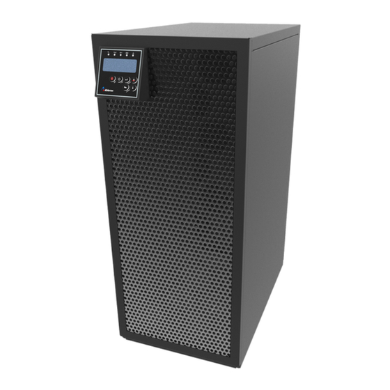
Summary of Contents for Ablerex Mars II
- Page 1 AB-MSII20000 User Manual...
-
Page 2: Table Of Contents
Table of Contents 1. Safety Instructions and Battery Care ..............2 1.1 Safety Instructions ....................2 1.2 Battery Care ......................3 2. UPS System Block Diagram ..................3 2.1 Single input System Block .................. 3 2.2 Dual input System Block ..................3 3. -
Page 3: Safety Instructions And Battery Care
1. Safety Instructions and Battery Care 1.1 Safety Instructions Because of small leakage currents generated by the EMI filter in the UPS it is necessary to double check that the ground wire of the UPS is properly grounded before connecting the UPS to the AC mains. To ensure safety in all applications where a UPS is hard wired to the electrical supply, ensure that the system is installed by a qualified electrical contractor. -
Page 4: Battery Care
6) Determine if battery is inadvertently grounded. If inadvertently grounded, remove source from ground. Contact with any part of a grounded battery can result in electrical shock. The likelihood of such shock can be reduced if such grounds are removed during installation and maintenance (applicable to equipment and remote battery supplies not having a grounded supply circuit). -
Page 5: Ups Functional Descriptions
3. UPS Functional Descriptions 3.1 Front Panel Display 3.1.1 Front Panel Function Explanations LCD Panel Symbol Description UPS On/Alarm Silence UPS OFF Switch Special functions log in/out To re-confirm the change of UPS Setting Go to next page Go to previous page or change the setting of the UPS. Solid green LED indicates that the utility input voltage is within the window. -
Page 6: Communication Port
3.1.3 Rear Panel O N O F F Par al l e l W or k C om m . Bus R s232 N ot f o r t e l e com m uni c at i o n ( t e l e phone) net w or k. -
Page 7: Installation And Operation
4. Installation and Operation Carefully inspect the UPS for shipping damage before installation. Retain the packing material for future use. 4.1 Unpacking 4.1.1 Standard package contents: User Manual Metal Accessories Kit as below: 4.2 Selecting Installation Position Install the UPS in a proper environment to minimize the possibility of damage to the UPS and to extend the life of the UPS. -
Page 8: Terminal Block Explanation
4.4 Terminal Block Explanation ● L11-L12: the terminal for Utility Input to provide the power source when the UPS is working under Utility mode ● G1: the terminal for UPS Input Ground L11-L12: UTILITY INPUT ● L21 、 L23 、 N21 、 L22 、 N22: the terminals for UPS Output ●... -
Page 9: Installation And Operation
4.5 Installation and Operation 4.5.1 Start Up in Normal Mode 4.5.1.1 Open the terminal block cover on the rear panel. (Refer to 3.1.3) Before starting the installation make sure the grounding is connected properly. 4.5.1.2 Make sure the utility breaker and the UPS’ Utility breaker and Bypass breaker are in the “Off” position. 4.5.1.3 Make sure the utility voltage matches the input voltage window of the UPS. - Page 10 4.5.2.2 Push the UPS On Switch once for approximately 5 seconds to awaken the UPS. The buzzer will sound twice. The LCD display will change from figure A to figure G for approximately 15 seconds. 4.5.2.3 Press the UPS On Switch again for about three seconds until the LCD display changes from figure G to figure H.
- Page 11 4.5.4 UPS Default Data and Special Function Execution 4.5.4.1 After the UPS completely starts up, press the key to change the LCD display to figure Q1. buzzer “On” buzzer “Off” 4.5.4.2 Press the key to scroll through the UPS settings. The LCD will display in sequence figure Q1~Y. Self-test is “On”...
- Page 12 4.5.4.3 Press the scroll up key to execute special functions. The functions include buzzer ON (as in figure Q1), buzzer OFF (as in figure Q2, Alarm silence for UPS Warning), and self-test OFF (as in figure R1) or self-test ON (as in figure R2). The UPS will execute the battery test for ten seconds.
-
Page 13: Troubleshooting Guide
4.5.6.2.5 Even if the UPS lock problem is solved now, consult with your local distributor to make sure that the error condition is resolved. 4.5.7 Shut Off 4.5.7.1 Press the Off key for five seconds. The Inverter output will be turned off, and the output load will be supplied by the Bypass loop. The LCD will display figure B. -
Page 14: Specifications
7. Specifications UPS Model AB-MSII20000 INPUT Voltage Window 160-280 VAC (1Φ) Frequency 45-65 Hz Phase/Wire Single-Phase, Line1 + Line2 + PE Power Factor >0.9 (0.95) Current THD (100% linear load) <30% OUTPUT Voltage Window 220/230/240 VAC Selectable (208/120 VAC optional) Voltage Adjustment ±0%, ±1%, ±2%, ±3% Voltage Regulation... - Page 16 192321132154000...


Need help?
Do you have a question about the Mars II and is the answer not in the manual?
Questions and answers