
Related Manuals for Burmester 218


Summary of Contents for Burmester 218
-
Page 1: Table Of Contents
About this operation manual Permissible operating conditions Intended use SAFETY INSTRUCTIONS Meanings of warning symbols and words Important notes UNPACKING AND SETTING UP THE 218 Unpacking the 218 Scope of delivery Setting up the 218 OVERVIEW OF THE 218 Front of the 218... - Page 2 O P E R A T I O N M A N U A L OPERATING THE 218 Switching the 218 on and off at the device Switching the 218 on and off with the remote control Selection of LED colours Auto power down Remote...
- Page 3 3 | 4 6...
-
Page 5: Introduction
Introduction 5 | 4 6... - Page 6 M A N U A L Dear music lover, Congratulations on your purchase and thank you for choosing Burmester. You have chosen a product that combines absolute fidelity and uncompromising quality with technical innovation. Before using the device for the first time, we recommend that you read through the entire operation manual at least once so that you can make full use of the capabilities of this exceptional audio device.
-
Page 7: About This Device
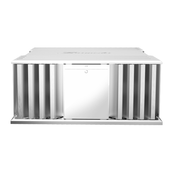
A M P L I F I E R About this device The 218 power amplifier is visually and sonically oriented towards our flagship 159 amplifier. At the same time, the Reference Line power amplifier consistently benefits from the experience and knowledge that Burmester has derived from four decades of successful amplifier development. -
Page 8: About This Operation Manual
Burmester power amplifier. Please read this operation manual in full and keep it in a safe place. Permissible operating conditions Please take care to only ever use your Burmester device under the following conditions: Maximum altitude: m 2000 Humidity <... - Page 9 9 | 4 6...
-
Page 11: Safety Instructions
Safety instructions 1 1 | 4 6... -
Page 12: Meanings Of Warning Symbols And Words
O P E R A T I O N M A N U A L Meanings of warning symbols and words The following warnings, symbols and warning words are used in this document: The general danger symbol in combination with the warning words CAUTION, WARNING DANGER... -
Page 13: Important Notes
If you cannot switch on the device even though the power supply is connected, the reason might be a faulty fuse. This can have various causes. Have the device checked by your Burmester dealer. Only authorized personnel are permitted to change the fuses. -
Page 15: Unpacking And Setting Up The 218
Unpacking and setting up the 218 1 5 | 4 6... -
Page 16: Unpacking The 218
Please check the scope of delivery for completeness and damage. If parts of the delivery are missing or if you notice any damage when unpacking the device, please do not connect them and consult your Burmester dealer instead. Scope of delivery... -
Page 17: Setting Up The 218
2 1 8 P O W E R A M P L I F I E R Setting up the 218 Place the device in a suitable location. ATTENTION! DANGER DUE TO IMPROPER INSTALLATION When choosing the installation location: Only place the device on level and load-bearing surfaces. -
Page 19: Overview Of The 218
Overview of the 218 1 9 | 4 6... -
Page 20: Front Of The 218
O P E R A T I O N M A N U A L FRONT OF THE 218 POWER button POWER LED Infrared sensor for the remote control 2 0 | 4 6... -
Page 21: Rear Of The 218
2 1 8 P O W E R A M P L I F I E R REAR OF THE 218 Input, right channel BurLink connection Power switch Device fuses (behind cover) Remote IN jack Remote OUT jack Input, left channel... -
Page 23: Connecting And Operating The 218
Connection and operation of the 218 2 3 | 4 6... -
Page 24: Connecting The 218
CONNECTION CABLES The inputs of the 218 are balanced (XLR 3pin) and have the following pin assignment: PIN1=GND, PIN2=NEG, PIN3=POS. For sound-related reasons, the inputs should be balanced. If your preamplifier does not have the appropriate outputs, you can use the enclosed adapters. -
Page 25: Power Connection
The voltage is set at the factory to the national standard for the country in which you purchased your Burmester device. If your device is to be operated with a different voltage than the one set at the factory, please contact your Burmester dealer. -
Page 26: Connection And Operating Modes
M A N U A L Connecting and operating modes Burmester stereo power amplifiers can be connected and operated in various ways. These are explained below. You should determine the optimum operating mode for you by ear and your personal preferences in order to achieve the best possible listening experience. - Page 27 2 1 8 P O W E R A M P L I F I E R FIGURE 1 STEREO MODE WIRING DIAGRAM RIGHT CHANNEL LEFT CHANNEL MAINS Do not switch your hi-fi system on again until you are sure that all the devices are connected correctly.
-
Page 28: Mono Mode
( ) of both units. Use Burmester XLR cables to extend the connection of the mono adapter to your preamplifier or amplifier inputs. Longer, custom-made Burmester adapter cables are also available on request. If your preamplifier does not have the appropriate outputs, you can use the enclosed adapters. - Page 29 2 1 8 P O W E R A M P L I F I E R FIGURE 2 MONO MODE WIRING DIAGRAM rechter Kanal linker Kanal RIGHT CHANNEL LEFT CHANNEL MAINS MAINS MONO Adapter MONO Adapter Do not switch your hi-fi system on again until you are sure that all the devices are connected correctly.
-
Page 30: Bi-Amp Mode
This leads to a significantly improved imaging and a more precise locatability of voices and instruments. For bi-amp mode, use one Burmester bi-amp adapter per amplifier. Ask your dealer for more information. ATTENTION! - Page 31 3 1 | 4 6...
-
Page 32: Vertical Bi-Amp Mode
( ) of both units. Use Burmester XLR cables to extend the connection of the bi-amp adapters to your preamplifier. Longer, custom-made Burmester adapter cables are also available on request. If your preamplifier does not have the appropriate outputs, you can use the enclosed adapters. - Page 33 2 1 8 P O W E R A M P L I F I E R FIGURE 3 WIRING DIAGRAM FOR VERTICAL BI-AMP MODE RIGHT CHANNEL LEFT CHANNEL High High BI-AMP Adapter BI-AMP Adapter 3 3 | 4 6...
-
Page 34: Horizontal Bi-Amp Mode
) of both units. The colour coding of the outputs is irrelevant here. Use Burmester XLR cables to extend the connection of the bi-amp adapters to your preamplifier or to the amplifier inputs. Longer, custom-made Burmester adapter cables are also available on request. - Page 35 2 1 8 P O W E R A M P L I F I E R FIGURE 4 WIRING DIAGRAM FOR HORIZONTAL BI-AMP MODE RIGHT CHANNEL LEFT CHANNEL High High BI-AMP BI-AMP Adapter Adapter 3 5 | 4 6...
-
Page 36: Operating The 218
Switching on the 218 Set the 218's power switch (6) on the back of the device to the ON position. The POWER LED ( ) lights up and the device is in standby mode. -
Page 37: Selection Of Led Colours
It can be switched on and off at the device, with the remote control or via BurLink. To switch APD on and off, the 218 must be switched on (ON state): Switching the APD on and off at the device... -
Page 38: Remote
If you connect the REMOTE OUT ( ) jack of the to the corresponding REMOTE IN jack on a Burmester device, you will be able to switch it on and off remotely when switching the on and off. In this operating mode, the takes over the master function. -
Page 39: Burlink
2 1 8 P O W E R A M P L I F I E R BURLINK Control systems such as PC, CRESTRON®, Nevo etc. can be connected to the BurLink connection. These allow convenient control of your entire system, e.g. -
Page 40: Error Indication And Troubleshooting
O P E R A T I O N M A N U A L Error indication and troubleshooting power amplifier is equipped with extensive protection circuits that protect it and the connected loudspeakers from damage in the event of a fault. The protective circuits of the react to various errors. - Page 41 2 1 8 P O W E R A M P L I F I E R OVERHEATING If the permissible operating temperature in the is exceeded, the protective circuit responds. Causes for excessive temperature in the may include: — Overloading the device by playing music at a very high sound pressure level for a long period of time —...
- Page 42 Offset error: “END_OFFSET:ERROR_R” or “END_OFFSET:ERROR_L” If the 218 does not return to normal operating mode after the measures described above, there are other causes. Switch off the device and disconnect it from the power supply by pulling out the power plug. Please contact your dealer.
-
Page 43: Warranty
We hereby guarantee that your Burmester product has successfully passed an extensive checkout routine and has left our factory in perfect shape. We provide a three-year warranty on your Burmester device. In order for the warranty to be valid, the device must have been connected and operated properly without overloading, the mechanical integrity of the device must not have been compromised, and the device must have been registered. -
Page 44: Technical Specifications
O P E R A T I O N M A N U A L Technical specifications of the 218 Two-channel DEVICE TYPE power amplifier DEVICE DIMENSIONS Width 496 mm Height 216 mm Depth 479 mm 42 kg Weight *The dimensions do not include the lengths of the plugs used for connection. - Page 45 2 1 8 P O W E R A M P L I F I E R POWER OUTPUT **Power output measured with model 218-240 at 230 V~, 50 Hz. POWER OUTPUT IN STEREO (IEC62368-1) per channel: 2 Ω 400 W 4 Ω...
- Page 46 O P E R A T I O N M A N U A L VERSION: BA_218_EN_1-1_2206 BURMESTER HOME AUDIO GMBH Wilhelm-Kabus-Straße 47 10829 Berlin Germany www.burmester.de 4 6 | 4 6...
Need help?
Do you have a question about the 218 and is the answer not in the manual?
Questions and answers