Table of Contents
Advertisement
Advertisement
Table of Contents

Subscribe to Our Youtube Channel
Related Manuals for Burmester 808 MK5


Summary of Contents for Burmester 808 MK5
- Page 1 P R E A M P L I F I E R Owner‘s Manual...
- Page 3 Please, talk to us about customization – even if it seems a little far-fetched to you. We gladly accept any technically reasonable challenge. Enjoy the music. Your Burmester team. Owner‘s Manual 808 MK5...
-
Page 4: Table Of Contents
Interconnect Cable BURMESTER SILVER . . . . . . . . . . . . . . . . . . -
Page 5: The System
The SySTem The System Front view of preamplifier Top view of preamplifier Rear view of preamplifier Front view of power supply Rear view of power supply Owner‘s Manual 808 MK5... -
Page 6: The 808 Mk5 In Brief
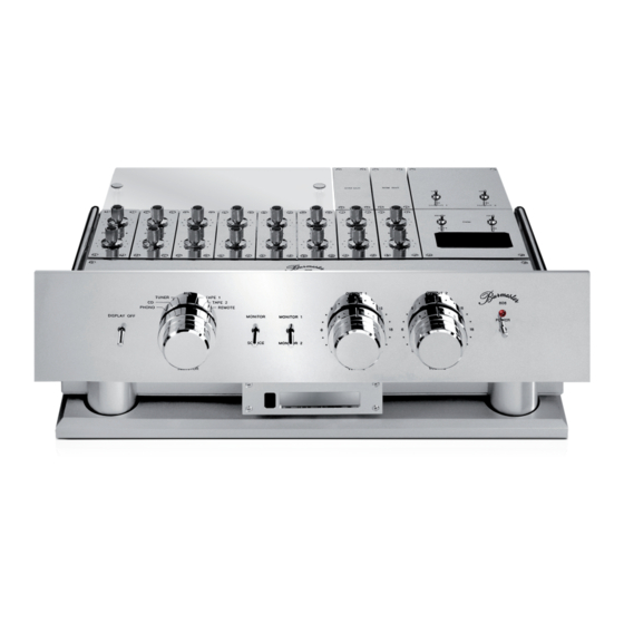
The SySTem The 808 MK5 in brief (1) POWER master switch for turning the power to the preamplifier on and off. (2) POWER LED illuminates when the preamplifier has been powered up. (3) SELECTOR knob - for switching between input modules and for activating the remote control mode (REMOTE) (4) MONITOR- / SOURCE- switch for comparing source and taped signal. - Page 7 (37) Preamplifier OUTPUT 1, L and R, balanced. (38) Preamplifier OUTPUT 2, L and R, balanced. (39) REM-OUT 1 output supplies the voltage to remotely switch other Burmester components. (40) REM-OUT 2 output supplies the voltage to remotely switch other Burmester components.
-
Page 8: The Flow Chart
The SySTem The Flow Chart... -
Page 9: Setting Up
Connect the power cord with the AC terminal and plug it into the wall outlet. Switch the power switch to ON and toggle the POWER master switch (1) up (on).. The preamplifier is now ready for action. ª Owner‘s Manual 808 MK5... -
Page 10: The Concept
The ConCepT The Concept The 808 MK5 is a unique preamplification system. This is true not only in reference to its most advanced electronic technology and highest quality manufacturing but also with regard to its design. Its wide-ranging operational possibilities have made it the standard of reference in preamplification and the work horse for many audio developers and audio magazines worldwide. -
Page 11: Why A Balanced Signal Path
This has distinct disadvantages which we avoid by carrying the balanced design into the first preamplification stage. For a better understanding of the functioning and the design of the 808 MK5 explained on the following pages, please also refer to “The System” on page 5 and “The Flow Chart”... -
Page 12: The Basic Unit
The BaSiC UniT The Basic Unit The basic unit consists of the following functions and features: • all controls and toggle switches • ten mounting slots for input/output modules • two volume control knobs • display (switchable) • digital level display/level control •... -
Page 13: Volume Controls
Display switch (10) switches the display on or off. Note that the unit reacts with a slight delay when this switch is thrown. If settings of the 808 MK5 are changed with controls (3), (4) or (5) or a remote signal is sent while the display has been switched off, it will illuminate briefly to acknowledge the change in the settings. -
Page 14: Input Terminals
The BaSiC UniT Adjusting a CD player: Put test CD into the player. Play 1 kHz/0 dB sinusoidal signal. Adjust both channels of the selected CD input module one after the other to an identical DISPLAY readout (1.0 V) using level controls (12) and (13). Adjusting a tuner: Unfortunately FM stations no longer broadcast test signals. -
Page 15: System Remote
The SYSTEM REMOTE CONTROL can control all components of our REFERENCE LINE and TOP LINE. The system remote of the 808 MK5 controls all functions of the SELECTOR knob (3) as well as volume and thus enables you to compare various signal sources without leaving your listening position. -
Page 16: The Input Modules
<1%. The level controls do not have the task to adjust for tolerances in the electronic circuitry of the 808 MK5. They are designed to correct possible channel imbalances in signal sources and to adjust various signal sources to the same output level. -
Page 17: Interconnects / Mounting Slots
For this we recommend - as for all interconnections of your stereo system – using our proprietary cable BURMESTER LILA 3 or BURMESTER SILVER. It is available in any custom length and with any plug combination and hook-up configuration, including a separate tonearm mass cable. -
Page 18: The Surround Thruput Module
The SUrroUnd ThrUpUT modUle The Surround Thruput Module Functional principle: With the Surround Thruput Module the 808 Mk 5 preamp can easily integrate surround components into a stereo system. To this end the XLR input TAPE 1 (35) located on the rear panel may be used to connect the two front channels of a surround decoder / processor. -
Page 19: The Phono Module 808Mc3 (Optional)
For balanced operation (BAL) the switches B_L (left channel) and B_R (right channel) must be switched to BAL position. Unbalanced operation: For unbalanced operation (UNBAL) the switches B_L (left channel) and B_R (right channel) must be switched to UNBAL position. Owner‘s Manual 808 MK5... -
Page 20: The Phono Module 808Mm2 (Optional)
The phono modUle 808mm2 (opTional) The Phono Module 808MM2 (optional) Impedance loading: Bank of dip switches for adapting the PHONO MM2 module to the system impedance of a wide range of phono cartridges. The input resistance of the PHONO MM2 module is 47 kΩ. left channel right channel Switch position ON: visible dot... -
Page 21: The Output Modules
• Use of two separate balanced power amplifiers or active speakers by adding the SYM OUT modules. You can operate the 808 MK5 with one or both output modules. The two available output modules are technologically identical and differ only in the engraving on the cover plate. -
Page 22: The Power Supply
CaUTion: To minimize intermodulation by the stray-field effect of the transformer the power supply should be located as far away from the 808 MK5 as possible. It should also not stand on or close to power cords and signal cables. -
Page 23: The Service
• Names and addresses of the original and/or present owner (if known). Keep us informed! We are very interested in your experiences with the 808 MK5. The reason is that we may use some ideas in future design and that your experiences may contain valuable information for other owners. -
Page 24: Interconnect Cable Burmester Silver
On the one hand, the equipment got better and better. On the other hand, the negative influence of the so-called electro smog got steadily worse. The interconnect BURMESTER SILVER is the result of our intense research and development. The two signal conductors are made from high-purity silver; they are triple-shielded: twice against electrical and once against magnetic interference. -
Page 25: Ac Cord Burmester Power
For the best possible power supply of our components we recommend our triple- shielded AC cord BURMESTER POWER. This cable is standard equipment for all of our Reference and TOP LINE and for some of our BASIC components. The cable can also be ordered as accessory in any custom length. -
Page 26: General Remarks & Technical Specifications
general remarkS & TeChniCal SpeCifiCaTionS General remarks & Technical Specifications General remarks Technical Specifications 808 MK 5 Dimensions (WxHxD): 482x170x385 mm (19x6.7x15.2 in.) (without plugs) Weight: 23 kg (approx. 47lbs.) (incl. Base) Power supply Dimensions (WxHxD): 482x95x285 mm (19x3.75x11.2 in.) (without plugs) Weight: 9 kg (approx. - Page 27 Owner‘s Manual 808 MK5...
- Page 28 BURMESTER AUDIOSYSTEME GMBH Wilhelm-Kabus-Straße 47 D-10829 Berlin Tel . +49 (0) 30 787968 – 0 Fax +49 (0) 30 787968 – 68 E-Mail: mail@burmester .de www .burmester .de Version 1.2 / 1611...
Need help?
Do you have a question about the 808 MK5 and is the answer not in the manual?
Questions and answers