Table of Contents
Advertisement
Quick Links
Installation and Operation Manual
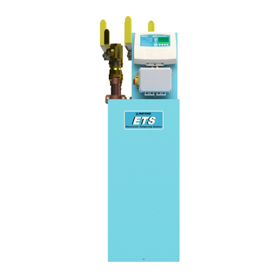
ETS
Electronic Tempering Station
WARNING
This Heat-Timer control is strictly an operating control; it should never be used as a primary limit or safety
control. All equipment must have its own certified limit and safety controls required by local codes. The installer
must verify proper operation and correct any safety problems prior to the installation of any Heat-Timer control.
059326‐00 Rev D
Advertisement
Table of Contents

Subscribe to Our Youtube Channel
Related Manuals for heat-timer ETS


Summary of Contents for heat-timer ETS
- Page 1 Electronic Tempering Station WARNING This Heat-Timer control is strictly an operating control; it should never be used as a primary limit or safety control. All equipment must have its own certified limit and safety controls required by local codes. The installer must verify proper operation and correct any safety problems prior to the installation of any Heat-Timer control.
-
Page 2: Table Of Contents
2 Table of Contents Detailed Operation. . . . . . . . . . . . . . . . . . . . . . . . . . . .3 Piping Diagrams. . . . . . . . . . . . . . . . . . . . . . . . . . . . . 44 Overview. . . . . . . . . . . . . . . . . . . . . . . . . . . . . . . . . .3 ETS Simplex . . . . . . . . . . . . . . . . . . . . . . . . . . . . . . 44 Controls, Indicators, and Connections . . . . . . . . . . . .4 ETS Duplex. . . . . . . . . . . . . . . . . . . . . . . . . . . . . . . 45 Specifications . . . . . . . . . . . . . . . . . . . . . . . . . . . . . . . .7 Troubleshooting . . . . . . . . . . . . . . . . . . . . . . . . . . . . 46 ETS Simplex (ETS‐15, ETS‐20, or ETS‐25) Specifications . . . . . . . . . . . . . . . . . . . . . . . . . . . .7 ETS Duplex (ETS‐30 or ETS‐40) Specifications . . . .8 ETS Sizing . . . . . . . . . . . . . . . . . . . . . . . . . . . . . . . . .9 ETV Platinum Plus Control Module. . . . . . . . . . . .10 ETV Platinum Plus Actuator. . . . . . . . . . . . . . . . . .10 ETV Platinum Plus Valve Body. . . . . . . . . . . . . . . .10 Motorized Safety Valve . . . . . . . . . . . . . . . . . . . . .11 Actuator Specifications. . . . . . . . . . . . . . . . . . .11 2‐Way Valve Specifications . . . . . . . . . . . . . . . . . .11 Installation Instructions. . . . . . . . . . . . . . . . . . . . . . .12 Supplied Materials . . . . . . . . . . . . . . . . . . . . . . . . .12 Required Materials (Not Supplied) . . . . . . . . . . . .12 Design Considerations . . . . . . . . . . . . . . . . . . . . . .12 ETS Assembly Handling Guidelines . . . . . . . . .12 Selecting a Location for the ETS Assembly . . .13... -
Page 3: Detailed Operation
ETV valve(s) to a full COLD position and close the TMC valve on the hot water supply to the mixing valve. In this Alarm condition the ETV module will close the alarm contacts tiggering the ETS audible alarm and enter into a manual reset condition. -
Page 4: Ets Simplex
4 ETS Installation and Operation Manual Controls, Indicators, and Connections Figure 1: ETS Simplex (ETS‐15, ETS‐20, or ETS‐25) Controls, Indicators, and Connections Item Description Item Description Electronic Temperature Controller Recirculation Water Line (ETV Platinum Plus) Disconnect Box with Transformer and Audible Alarm Boiler Feed Line Motorized Safety Valve Cold Water Line ETV Valve Body with Actuator Tempered Water Line Temperature Sensor 10 Hot Water Line 059326‐00 Rev D Heat‐Timer Corp. -
Page 5: Ets Duplex
Controls, Indicators, and Connections 5 Figure 2: ETS Duplex (ETS‐30 or ETS‐40) Controls, Indicators, and Connections Item Description Item Description Electronic Temperature Controller Hot Water Line (ETV Platinum Plus) Disconnect Box with Transformer and Audible Alarm Boiler Feed Line Temperature Gauge Cold Water Line ETV Valve Body with Actuator Recirculation Water Line Motorized Safety Valve 10 Tempered Water Line 059326‐00 Rev D Heat‐Timer Corp. - Page 6 6 ETS Installation and Operation Manual Figure 3: ETV Platinum Plus Controls, Indicators, and Connections Item Description Item Description Output Status LEDs Prove Input Connection See “ETV Platinum Plus Control Module Output Status LEDs” on page 22. Digital Display EMS Remote Setpoint Connection See “Display and Variable‐Function Buttons” on page 22. Variable‐Function Buttons Program/Run Switch See “Display and Variable‐Function Buttons” on Places the ETV Platinum Plus in programming page 22. mode or run (normal operation) mode. NOTE: Programming mode may be password protected. Internet/BACnet/Modbus Connection Communication Modem Reset Communications interface NOTE: Used if internet communication is lost for more than one hour. 059326‐00 Rev D Heat‐Timer Corp.
-
Page 7: Specifications
Specifications 7 Specifications ETS Simplex (ETS‐15, ETS‐20, or ETS‐25) Specifications Figure 4: ETS Simplex Dimensions Table 1: ETS Simplex Dimensions (in inches) Model ETS‐15 18.25 30.50 59.75 41.75 12.00 54.00 8.00 2.88 2.75 9.25 15.50 6.50 10.00 ETS‐20 18.25 30.50 59.75 41.75 12.00 55.00 8.00 2.88 2.75 9.25 15.50 6.50 10.00 ETS‐25 18.25 30.50 59.75 41.75 12.00 58.00 8.00... -
Page 8: Ets Duplex (Ets-30 Or Ets-40) Specifications
8 ETS Installation and Operation Manual ETS Duplex (ETS‐30 or ETS‐40) Specifications Figure 5: ETS Duplex Dimensions Table 2: ETS Duplex Dimensions (in inches) Model ETS‐30 36.00 30.50 59.75 41.75 12.00 60.00 70.00 14.25 3.50 4.25 11.75 20.25 26.50 32.75 ETS‐40 36.00 30.50 59.75 41.75 12.00 61.00 71.00 14.25 3.50 4.25 11.75 20.25 26.50 32.75 059326‐00 Rev D Heat‐Timer Corp. -
Page 9: Ets Sizing
Specifications 9 ETS Sizing ETS Model Pressure Drop (PSI) ETS‐15 ETS‐20 ETS‐25 ETS‐30 ETS‐40 Gallons Per Minute Pipe Size Part ETV Valve Safety Valve Heat Source Weight Model Number Size Size Mixed Cold Recirc Cold Supply (approx.) ETS‐15 915800‐15 1 1/2" 1 1/2" 1 1/2" 1 1/2" 1 1/2" 1 1/4" 1 1/2" ETS‐20 915800‐20 2" 2" 2"... -
Page 10: Etv Platinum Plus Control Module
10 ETS Installation and Operation Manual ETV Platinum Plus Control Module Voltage Input: . . . . . . . . . . . . . . . . . . . . . . . . . . . . . . . . . . . . . . . . . . . . . . . . . . . . . . . . . . . . . . . . . . . . . . .120Vac 60Hz Maximum Input Rating:. . . . . . . . . . . . . . . . . . . . . . . . . . . . . . . . . . . . . . . . . . . . . . . . . . . . . . . . . . . . . . . . . 48VA max Dimensions (W x H x D): . . . . . . . . . . . . . . . . . . . . . . . . . . . . . . 11” x 9” x 3 ¾” (279.4mm x 228.6mm x 95.25mm) Weight: . . . . . . . . . . . . . . . . . . . . . . . . . . . . . . . . . . . . . . . . . . . . . . . . . . . . . . . . . . . . . . . . . . . . . . . . . . 2.5lbs (1.13kg) Modes of Operation: . . . . . . . . . . . . . . . . . . . . . . . . . . . . . . . . . . . . . . . . . . . . . . . . . . . . . . . . . ETV, TMC, ETV + TMC ETV Setpoint:. . . . . . . . . . . . . . . . . . . . . . . . . . . . . . . . . . . . . . . . . . . . . . . . . . . . . . . . . . . . 40°F to 200°F (4°C to 93°C) Alarm Setpoint:. . . . . . . . . . . . . . . . . . . . . . . . . . . . . . . . . . . . . . . . . . . . . . . . . . . . . . . . . . 40°F to 200°F (4°C to 93°C) Modulation Output Signal: . . . . . . . . . . . . . . . . . . . . . . . . . . . . . . . . . . .0‐10V (default), 2‐10V, 0‐5V, 1‐5V, 4‐20mA Output Relays: . . . . . . . . . . . . . . . . . . . . . . . . . . . . . . . . . . . . . . . . . . . . . . . . . . . . . . . . . . . . . . . . . . . . 1 TMC Lockout 1 Modem Reset 1 Valve Output Output Relay Rating: . . . . . . . . . . . . . . . . . . . . . . . . . . . . . . . . . . . . . . . . . . . . . . . .TMC Lockout: 3A at 120Vac 60Hz Modem Reset: 5A resistive at 120Vac 60Hz Valve Output: 1A inductive at 120Vac 60Hz Inputs: . . . . . . . . . . . . . . . . . . . System Temperature, Aux Temp 1 (Temp or Switch), Aux Temp 2 (Temp or Switch) Flow Prove, Remote Setpoint (4‐20mA) User Interface:. . . . . . . . . . . . . . . . . . . . . . . . . . . . . . . . . . . . . . . . . . . . . . . . . . . . . . . . . . . . . . . . . . . . . Digital Display Display Units: Temperature (°F and °C) Status Indicators (3 LEDs) Variable‐Function Buttons (4) ETV Platinum Plus Actuator Voltage Input: . . . . . . . . . . . . . . . . . . . . . . . . . . . . . . . . . . . . . . . . . . . . . . . . . . . . . . . . . . . . . . . . . . . . . . . .24Vac 60Hz Power Consumption: . . . . . . . . . . . . . . . . . . . . . . . . . . . . . . . . . . . . . . . . . . . . . . . . . . . . . . . . . . . . . . . . . . . 18VA max Input Signal: . . . . . . . . . . . . . . . . . . . . . . . . . . . . . . . . . . . . . . . . . . . . . . . . . . . . . . . . . . . . . . . . . . . . . . . . . . . . . 0‐10V Weight: . . . . . . . . . . . . . . . . . . . . . . . . . . . . . . . . . . . . . . . . . . . . . . . . . . . . . . . . . . . . . . . . . . . . . . . . . . 2.6 lbs (1.2 kg) -
Page 11: Motorized Safety Valve
Specifications 11 Motorized Safety Valve Actuator Specifications 2‐Way Valve Specifications Construction:. . . . . . . . . . . . . . . . . . . . . . . . . . . . . . . . . . . . . . . . . . . . . . . . . . . AISI 316 Stainless 2‐Piece Valve Body Port Size: . . . . . . . . . . . . . . . . . . . . . . . . . . . . . . . . . . . . . . . . . . . . . . . . . . . . . . . . . . . . 1/2" – 3" (12.7mm – 76.2mm) Pressure Rating: . . . . . . . . . . . . . . . . . . . . . . . . . . . . . . . . . . . . . . . . . . . . . . . . . . . . . . . . . . . 1000 psi / 150 psi Steam Temperature Rating:. . . . . . . . . . . . . . . . . . . . . . . . . . . . . . . . . . . . . . . . . . . . . . . . . . .–4°F to 366°F (–20°C to 186°C) Packing: . . . . . . . . . . . . . . . . . . . . . . . . . . . . . . . . . . . . . . . . . . . . . . . . .P.T.F.E. Seals and Double O‐ring Stem Packing Blowout‐Proof Valve Stem Actuator Mount:. . . . . . . . . . . . . . . . . . . . . . . . . . . . . . . . . . . . . . . . . . . . . . . . . . . . . . . . . . . . . . . . . . . . ISO 5211 Pad 059326‐00 Rev D Heat‐Timer Corp. -
Page 12: Installation Instructions
12 ETS Installation and Operation Manual Installation Instructions The installation process for ETS consists of the following basic steps: 1. Initial installation (see “Design Considerations” on page 12). 2. Installing the ETS assembly (see page 16). 3. Connecting the ETS assembly power wiring (page 18). 4. Wiring the ETV Platinum Plus (see page 41). 5. Starting up the ETS (page 22). Supplied Materials The following materials are supplied with the control module: • Installation and Operation Manual (p/n 059326‐00) • Warranty Card (p/n 059115‐00) Required Materials (Not Supplied) The following materials/tools are required for installation, but are not supplied: • General tool kit (screwdrivers, wire strippers, power drill, etc.) • 14 AWG cable (used for incoming 120Vac power) • 18 AWG cable (Heat‐Timer p/n 703001‐01 or equivalent #18/2 cable) for actuator wiring • Electrical conduit • Piping and fitting material Design Considerations When installing the system, certain design considerations must be taken into account. These include: • ETS Assembly Handling Guidelines (see page 12) •... -
Page 13: Selecting A Location For The Ets Assembly
Installation Instructions 13 Selecting a Location for the ETS Assembly Select an appropriate location to install the ETS assembly. The location must meet the following minimum requirements: • The ETS assembly is not intended for outdoor installation. • Keep the distance between the ETS assembly and the water heating source to a minimum. This reduces piping heat loss and provides minimal friction loss. • The ETS assembly location should be where leakage from the piping field connections will not cause damage to the surrounding area. • Consider the location of new or existing piping and electrical. Recommended Clearances To ensure serviceability of the ETS assembly, the following minimum clearances must be met: • Left and Right Sides: 18 inches • Top: 24 inches • Front: 24 inches • Rear: 0 inches General Electrical Guidelines All assemblies require a 120Vac line voltage dedicated circuit with a 12 Amp circuit breaker. 059326‐00 Rev D Heat‐Timer Corp. -
Page 14: General Piping Guidelines
14 ETS Installation and Operation Manual General Piping Guidelines • All piping must meet or exceed all applicable local, state, and/or federal guidelines, codes, regulations, and laws. • Support all piping using hangers. DO NOT support piping by the unit or its components. • Use isolation valves (provided) to isolate the ETS assembly. • Use unions (provided) to allow for servicing and, if required, removal of the valve and other components. • Include drain valves (provided) to assist in servicing of the ETS assembly. • Use a generous amount of pipe thread sealant. DO NOT use pipe thread tape. When using the valve in a domestic water application, ensure the thread sealant is compliant with domestic water application and meets NSF 61 requirements. Isolation Valves Isolation Valves Unions Unions Drain Valve Drain Valve Figure 6: ETS Assembly (Rear View) Isolation Valves, Unions, and Drain Valves 059326‐00 Rev D Heat‐Timer Corp. -
Page 15: Recirculation Pump Sizing
Installation Instructions 15 Recirculation Pump Sizing For proper operation of the ETS, the assembly must be installed in a system with constant recirculation. The ETS provides a dedicated recirculation connection. For optimum valve function, it is recommended that the building recirculation temperature is at least 7°F lower than the desired setpoint temperature. In addition, it is recommended that the HOT water supplied to the ETV valve is at least 20°F above the desired setpoint. The recirculation pump (not provided) must be properly sized for the following recirculation rates: Table 3: ETS Recommended Recirculation Flow Rates Recirculation Model Flow Rate ETS‐15 10 gpm ETS‐20 15 gpm ETS‐25 15 gpm ETS‐30 30 gpm ETS‐40 30 gpm In systems without a building recirculation line, it is recommended that a flow switch (not provided) is installed. WARNING HEALTH RISK! Any domestic hot water system that does not utilize a constant building recirculation line poses a potential risk of stagnant water in the system. Stagnant water provides ideal conditions for the growth of bacteria, such as Legionella. The flow switch should be located on the MIXED outlet field piping above the ETS assembly. Activation of the flow switch should be at the lowest potential draw of the system. Refer to “Wiring the Flow Prove” on page 42 for wiring to the ETV Platinum Plus module for a flow switch (Prove). Refer to “Flow Switch” on page 28 for proper STARTUP menu settings for installations using a flow switch. 059326‐00 Rev D Heat‐Timer Corp. -
Page 16: Installing The Ets Assembly
13). 3. Ensure the ETS assembly is level. Use shims (not provided) if necessary. 4. If required by local codes, secure the ETS assembly frame to the floor and/or wall: a. Drill into the floor and/or wall through holes in the ETS assembly frame (Figure 7 and Figure 8). b. Install the appropriate anchors (not provided) and secure the frame to the floor and/or wall. NOTE: The assembly may be secured to the floor and/or the wall using the holes in the cross members of the frame. Anchor bolts are supplied by others. - Page 17 Installation Instructions 17 NOTE: The assembly may be secured to the floor and/or the wall using the holes in the cross members of the frame. Anchor bolts are supplied by others. Figure 8: ETS Duplex – Floor Mounting Anchor Locations 059326‐00 Rev D Heat‐Timer Corp.
-
Page 18: Connecting The Ets Assembly Power Wiring
18 ETS Installation and Operation Manual Connecting the ETS Assembly Power Wiring WARNING ELECTRICAL SHOCK HAZARD! For your safety, to avoid the risk of electric shock, disconnect electrical power to the device before servicing or making any electrical connections. DO NOT re‐connect electrical power until ALL wiring is completed. Failure to do so may result in severe personal injury or death. Use a separate circuit breaker for the control. Do not share the control power with any other major equipment, pumps, or motors. Heat‐Timer recommends the installation of a surge suppressor and a power switch before the power line connection. All wiring must meet or exceed all applicable local, state, and/or federal guidelines, codes, regulations, and laws. 1. De‐energize the circuit that will provide power to the ETS by turning off the appropriate circuit breaker. 2. Remove the Disconnect Panel front plate by removing the four mounting screws. Disconnect Panel 3. Run the 120Vac power wiring through one of the knockouts located on the bottom of the ETS Disconnect Panel. CAUTION The input power wires must be N.E.C. Class 1. Class 1 voltage wiring must use a different enclosure knockout and conduit than any sensor wiring. 4. Connect the HOT line to the BLACK wire pigtail using the provided wire nut. 5. Connect the NEUTRAL line to the WHITE wire pigtail using the provided wire nut. 059326‐00 Rev D Heat‐Timer Corp. - Page 19 41 before proceeding to Step 9. 9. Apply power to the ETS assembly. NOTE: Once power is supplied to the ETS it will take approximately 2 minutes to fully charge the Lost of Power (LOP) capacitor in the ETV valve actuator(s). Once fully charge the LOP capacitor will be able to power the actuator and position the valve to a full COLD position during a loss of power condition.
- Page 20 20 ETS Installation and Operation Manual Figure 9: ETS Simplex Factory Wiring Diagram 059326‐00 Rev D Heat‐Timer Corp.
- Page 21 Installation Instructions 21 Figure 10: ETS Duplex Factory Wiring Diagram 059326‐00 Rev D Heat‐Timer Corp.
-
Page 22: Ets Startup
22 ETS Installation and Operation Manual ETS Startup ETS startup consists of the following steps: 1. Programming the ETV Platinum Plus. 2. Calibrating the Actuator. Programming the ETV Platinum Plus ETV Platinum Plus Control Module Output Status LEDs The ETV Platinum Plus has three output status LEDs: Description Actuator Signal Indicates the change in the mixing valve opening. Any time the ETV Platinum Plus changes the valve opening, the LED will turn on for approximately one second. If the LED remains lit, the control is sending the Actuator a “fully open” or “fully close” signal. No Flow Indicates no flow exists when lit. NOTE: This indicator is only applicable when using a Flow Switch as PROVE of flow in applications without a building recirculation system. TMC Lockout Indicates the control is in lockout mode when lit. System temperature rises above the (High Temperature Alarm Limit for the Trigger Delay period, or a sensor has been disconnected. See “Alarm Limit) Messages” on page 24. After the alarm condition has been corrected, the ETV Platinum Plus must be manually reset to resume normal operation. Display and Variable‐Function Buttons The ETV Platinum Plus display shows the system sensor temperature and operation messages. By default, the display shows the current Setpoint, Alarm Limit, or the Modulation Output percentage. See “Display Icons and Messages” on page 24 for more information. The area above the variable‐function buttons displays the current function for each button. This area may not be displayed if button activity is stopped for 30 seconds in the ... - Page 23 ETS Startup 23 The display button functions vary based on the current screen displayed, as described in the following table: Button Screen ▲ ▼ Left Right Default Has no function MENU LOCKOUT In Lockout Enters the menu mode. Enters the Lockout Reset Menu. Has no function RESET Lockout Reset Ends current alarm. SELECT Menu Scrolls through the menu. BACK Selects current menu item. SAVE Goes back one menu step. Setting Changes the current setting value. Saves current setting. NEXT or EXIT Configuration Jumps to next view or exits. Default Display NOTE: The area above the variable function buttons that describe the button’s function may not be displayed due to inactivity. Pressing the far‐right button in the default display will enter into the Menu screen. 059326‐00 Rev D Heat‐Timer Corp.
- Page 24 24 ETS Installation and Operation Manual Display Icons and Messages The following icons and messages may be displayed by the ETV Platinum Plus. Message Description The battery icon blinks when the battery is weak. 2 TMC Limit = 160°F The alarm is set to be triggered when the system temperature exceeds the displayed setting for the specified Delay Alarm period. See “TMC Setpoint” on page 33. Valve Close! See Log The system temperature exceeded the alarm limit. TMC lockout has occurred (the control closed the TMC valve). View the alarm logs (see “Alarm Log” on page 38). When in the ETV + TMC mode, this message will alternate with the “TMC Limit = 160°F” message. 4 No Flow! The Flow Switch option is enabled and no flow is detected. See “Wiring the Flow Prove” on page 42. 6 Target Temperature The control target temperature setting. EMS Open/Short When EMS is used and the signal fails, “EMS Open/Short” is shown. 7 Value or Switch Icon When Aux 1 is configured as Temperature input, the value is shown. When Aux 1 is configured as Switch, the switch status icon is shown. 8 Value or Switch Icon When Aux 2 is configured as Temperature input, the value is shown. When Aux 2 is configured as Switch, the switch status icon is shown. 9 Communication Lost! Internet Communication (ICMS) option only. ...
- Page 25 ETS Startup 25 Setting the Display Contrast NOTE: The display contrast can only be changed when no alarm is active. 1. At the default screen, press and hold the left‐most button for 5 seconds. Continue to hold the button while making adjustments. 2. Use the up and down buttons to change the contrast setting (0–30, default = 20). 3. Release the left‐most button when the desired setting is reached. Resetting to Factory Default To set the ETV Platinum Plus back to its original factory default settings: 1. Remove power from the ETV Platinum Plus. 2. Press and hold the two right‐most buttons on the ETV Platinum Plus while powering the control on. 3. Release the buttons when instructed to do so on the display. After resetting the control, the ETV Platinum Plus will go to the Startup menu (see “System Startup Menu” on page 26). 059326‐00 Rev D Heat‐Timer Corp.
-
Page 26: Etv Platinum Plus Programming Menus
26 ETS Installation and Operation Manual ETV Platinum Plus Programming Menus System Startup Menu When the ETV Platinum Plus is first powered‐on and initialization is complete, the System Startup menu screens appear. Follow the System Startup menu screens to program the unit. NOTE: If the System Startup menu screens to not appear, the ETV Platinum Plus has already been configured. To check the configuration or to make changes, select System Startup from the Main menu. 059326‐00 Rev D Heat‐Timer Corp. - Page 27 ETS Startup 27 Display Unit Selections: °F, °C Default: °F Menu Path: /System Startup > Display Unit Description: This option changes the sensors' display and all temperature settings standard to Fahrenheit or Celsius. Setpoint Input Selections: Local Input, Remote 4-20mA Default: Local Input If Remote 4-20mA is selected: 4mA range: Default: 60°F/16°C (40°F/4.5°C to 200°F/93°C) Default: 180°F/82°C 20mA range: (40°F/4.5°C to 200°F/93°C) Menu Path: /System Startup > Display Unit > Setpoint Input Description: The ETV Platinum Plus can maintain a setpoint temperature either by selecting the temperature locally at the control or by receiving a remote setpoint temperature as a 4‐20mA signal from EMS. See “Wiring the 4‐20mA Remote Setpoint” on page 42. If Remote 4‐20mA was selected, the temperature range must be selected using the 4mA and 20mA settings. If the Control Mode is set to ETV or ETV + TMC options, the Remote 4‐20mA will always apply to the ETV Setpoint. However, if the Control Mode is set to TMC, the Remote 4‐20mA will apply to the Alarm Limit. Any signal below 2mA or above 22mA will close the motorized mixing valve in ETV or ETV + TMC mode. In the TMC mode, it will close the TMC valve and trigger the alarm. The display will show the message “EMS Open” or “EMS Short” to indicate this status. 059326‐00 Rev D Heat‐Timer Corp.
- Page 28 28 ETS Installation and Operation Manual Aux1/Aux2 Input Selections: None, Temperature, Default: None Switch Menu Path: /System Startup > Display Unit > Setpoint Input > AUX1 Input > AUX2 Input Description: AUX1 and AUX2 inputs can be configured as a Switch sensor (which detects open or close conditions) or as a Temperature sensor (which can be used for anything that is temperature‐related, including return and hot supply). Return Comp. Selections: None, Aux1, Aux2 Default: None Menu Path: /System Startup > Display Unit > Setpoint Input> AUX1 Input > AUX2 Input > Return Comp. Description: If AUX1 or AUX2 input is configured as “Temperature”, Return Comp can be used (Feed Forward). This is useful for improving the recovery when the Return temperature changes rapidly. Hot Supply Comp. Selections: None, Aux1, Aux2 Default: None Menu Path: /System Startup > Display Unit > Setpoint Input> AUX1 Input > AUX2 Input > Return Comp. > Hot Supply Comp. Description: If AUX1 or AUX2 input is configured as “Temperature”, Hot Supply Comp can be used. This is useful for improving the recovery when the Hot Supply temperature changes rapidly. Flow Switch Selections: No, Yes Default: No Menu Path: /System Startup > Display Unit > Setpoint Input> AUX1 Input > AUX2 Input > Return Comp. > Hot Supply Comp. > Flow Switch Description: All mixing valves require constant flow for accurate temperature control. The ETS can accept a dry‐contact ...
- Page 29 ETS Startup 29 Limit Valve POS. Selections: 0% to 100% Default: 50% Menu Path: /System Startup > Display Unit > Setpoint Input> AUX1 Input > AUX2 Input > Return Comp. > Hot Supply Comp. > Flow Switch = Yes > Limit Valve POS. Description: When Flow Switch = Yes and no flow is detected, the control will adjust the mixing valve to the defined opening percentage if the valve is currently open more than the set value. If the current valve opening percentage is less than the set value, the valve will remain in its current position. For example, if Limit Valve POS. is 30% and no flow is detected when the current valve opening percentage is 50%, the control adjusts the mixing valve down to the 30% open position. If the current valve opening percentage is 20% when no flow is detected, the valve will remain at the 20% open position. Modulation Type Selections: 0-10V, 2-10V, 0-5V, Default: 0-10V 1-5V, 4-20mA Menu Path: /System Startup > Display Unit > Setpoint Input> AUX1 Input > AUX2 Input> ... > Modulation Type Description: The ETV is capable of operating a variety of 3‐way valve Actuators. Heat‐Timer factory‐supplied Actuators are set to 0‐10V signal. The selection must match the Actuator modulation signal. Network Communication Options Selections: Network communications settings Menu Path: /System Startup > ... > Modulation Type > {comm options} Description: During startup, the ETV Platinum Plus detects an installed network option. If no network is detected, network configuration screens are bypassed. • RINET–Internet ID (Solo, 1–32, or Custom) •...
- Page 30 30 ETS Installation and Operation Manual Set Present Date and Time Selections: Numerical values for Month, Day, Year, and Time Menu Path: /System Startup > ... > Modulation Type > {comm options} > Set Present Date > Set Present Time Description: Sets the present date and time on the control. The date and time are used to regulate the Schedule. The ETV battery is used to maintain the date and time during power outages. Daylight Saving Selections: Enable, Disable Default: Enable Menu Path: /System Startup > ... > Set Present Date > Set Present Time > Daylight Saving Description: Enables or disables Daylight Saving mode. When enabled, the present time on the control will be automatically adjusted for Daylight Savings Time. 059326‐00 Rev D Heat‐Timer Corp.
-
Page 31: Main Menu
ETS Startup 31 Main Menu The main Menu is used to configure setpoints, TMC high temperature limits, and modulating gain. 059326‐00 Rev D Heat‐Timer Corp. - Page 32 32 ETS Installation and Operation Manual Setpoint Selections: 40°F to 200°F/ Default: 100°F/38°C (ETV) (4.5°C to 93°C) 110°F/43°C (TMC) Menu Path: /Setpoint Description: The Setpoint is the mixed valve outlet temperature the ETV will hold during normal operation. The temperature may fluctuate slightly around the Setpoint. The amount of fluctuation is controlled by the Gain setting (see “Modulating Gain” on page 34.) If the Setpoint Input was set to EMS 4‐20mA, the setpoint will be available as read‐only and can only be changed remotely using the 4‐20mA input signal (see “Setpoint Input” on page 27). If a schedule is set, the schedule overrides the Setpoint (see “Schedules Menu” on page 35). If the Setpoint is set to a value higher than 125°F (52°C), a scald warning is displayed. Select OK to acknowledge the warning and keep the current temperature setting. Select EDIT to return to the Setpoint screen to enter a lower temperature setting. WARNING SCALD HAZARD! Water temperatures over 125°F (52°C) can instantly cause severe burns. Children, disabled, and the elderly are at highest risk of being scalded. If anyone using hot water in the building fits the above description, or if local codes or state laws require specific water temperatures at the outlet, it is recommended to not exceed at Setpoint limit of 125°F (52°C). Water drained from system drain valves may also be extremely hot. Make sure all connections are tight and direct all water flow away from personnel. 059326‐00 Rev D Heat‐Timer Corp.
- Page 33 ETS Startup 33 TMC Setpoint Selections: 40°F/4.5°C to 200°F/93°C Default: 110°F/43°C Menu Path: /TMC Setpoint Description: The TMC Setpoint is the mixed valve outlet temperature above which the ETV Platinum Plus will close the TMC valve and trigger an alarm (high temperature limit). This action prevents the mixed outlet from reaching excessive temperatures. An alarm message is displayed (see “Alarm Messages” on page 24) and the event will be recorded in the Alarm Log (see “Alarm Log” on page 38). If the Setpoint Input was set to EMS 4‐20mA, the TMC Setpoint can only be changed remotely using the 4‐20mA input signal. It will be available as read‐only through the control (see “Setpoint Input” on page 27). A TMC Trigger Delay can be adjusted to help eliminate false alarms (see “TMC Trigger Delay” on page 33). WARNING SCALD HAZARD! Water temperatures over 125°F (52°C) can instantly cause severe burns. Children, disabled, and the elderly are at highest risk of being scalded. If anyone using hot water in the building fits the above description, or if local codes or state laws require specific water temperatures at the outlet, it is recommended to not exceed at Setpoint limit of 125°F (52°C). Water drained from system drain valves may also be extremely hot. Make sure all connections are tight and direct all water flow away from personnel. TMC Trigger Delay Default: 15 sec Selections: 0 to 60 seconds Menu Path: /TMC Setpoint > TMC Trigger Delay Description: The TMC Trigger Delay prevents the alarm from being triggered immediately and the TMC valve from closing unless the alarm situation is maintained for the full delay period. This helps eliminate false alarm situations that normally may only last for a few seconds. 059326‐00 Rev D Heat‐Timer Corp.
- Page 34 34 ETS Installation and Operation Manual Modulating Gain Selections: -10 to +10 Default: +0 Menu Path: /Mod. Gain Description: The Modulating Gain adjusts the PID aggressiveness of the control. The higher the gain, the more aggressive the ETV Platinum Plus adjusts the mixing valve based on changes in water temperature. If the water temperature tends to oscillate quickly above and below the desired setpoint, reduce the gain. If the water temperature tends to stay consistently below or above the Set Point, increase the gain. Start with a gain of “0”. Before making any additional gain changes, always wait at the least ten minutes after adjusting the gain to determine its affect on the system. 059326‐00 Rev D Heat‐Timer Corp.
-
Page 35: Schedules Menu
ETS Startup 35 Schedules Menu The Schedules menu is used to configure schedules that are used to set an absolute temperature. Up to four periods can be configured per day. Each period can have its own start time and temperature setting, and will maintain that temperature setting until the next scheduled period start time. NOTE: If a schedule is set, the schedule overrides the Setpoint setting (see “Setpoint” on page 32). 059326‐00 Rev D Heat‐Timer Corp. - Page 36 36 ETS Installation and Operation Manual Select Days Selections: Weekdays, Weekends, Everyday, or specific days Menu Path: /Schedules > Temp. Schedules > Select Days Description: Select the days or group of days (weekends, weekdays, or everyday) to apply the schedule. Set Schedule Start Time Selections: Numerical values for Time Menu Path: /Schedules > Temp. Schedules > Select Days > Set SCH‐1 Start Time Description: Specifies the schedule start time. Four Schedule Start Times can be set for each day. Each start time has its own temperature setting (see “Set Schedule Temperature” on page 36). Set Schedule Temperature Selections: 40°F/4.5°C to 200°F/93°C Default: 0°F/-18°C Menu Path: /Schedules > Temp. Schedules > Select Days > Set SCH‐1 Start Time > Set SCH‐1 Override Description: The the Temp. setting overrides the Setpoint and sets the system temperature to the entered value. The new Schedule Setpoint temperature is displayed on the screen with an asterisk (for example, 130F*). All Temp. settings for each day of the week must be set to guarantee that the default setting is replaced. 059326‐00 Rev D Heat‐Timer Corp.
-
Page 37: Maintenance Menu
ETS Startup 37 Maintenance Menu The Maintenance menu is used to modify critical system behavior and view previous alarm conditions. It should only be used by system installers. Password Enable Selections: No, Yes Default: No Menu Path: /Maintenance > Password Enable Description: When set to Yes, a password must be entered in order to access the ETV Platinum Plus programming menus. When enabled, the password can be set or changed. When setting/changing the password, it must be entered twice and both entries must match. If the password entries do not match, an error is displayed and the password must be re‐entered. 059326‐00 Rev D Heat‐Timer Corp. - Page 38 38 ETS Installation and Operation Manual Alarm Log Selections: Scroll list Menu Path: /Maintenance > Alarm Log Description: The ETV Platinum Plus keeps a log of the last 99 alarms, including their date and time. For a list of possible alarms included in the Alarm Log, see “Alarm Messages” on page 24. Use the two middle buttons to scroll through the alarm list. Single‐press the Erase button to delete the currently displayed alarm. Long‐press (at least 5 seconds) the Erase button to delete all alarm entries. Configuration Selections: None Menu Path: /Maintenance > Configuration Description: The Configuration menu provides access to screens that display the current configuration of the ETV Platinum Plus. Available information includes: software version, serial number, startup settings, communication settings, and battery level. Press the Next button to advance through the configuration screens. 059326‐00 Rev D Heat‐Timer Corp.
-
Page 39: Lockout Menu
ETS Startup 39 Lockout Menu The Lockout menu is used to reset system lockouts. NOTE: Under specific conditions, the control triggers the alarm and logs the event in the Alarm Log (see “Alarm Log” on page 38). Reset Lockout Selections: RESET Default: N/A Menu Path: Lockout Description: The TMC Lockout outputs energize whenever the System Temperature rises above the Alarm Limit for the Trigger Delay period. To reset the lockout, the conditions causing the lockout must be corrected first. Then, the lockout can be reset using the Reset Lockout menu. If the lockout was reset before the conditions are corrected, the lockout output will immediately be re‐activated. 059326‐00 Rev D Heat‐Timer Corp. -
Page 40: Calibrating The Actuator
40 ETS Installation and Operation Manual Calibrating the Actuator NOTE: Each time the Actuator is assembled to the valve, the Actuator must be calibrated. 1. Close the valve feeding the tempering valve HOT port. 2. Ensure the Actuator Manual Tab is in the Normal Operation position (UP). 3. Remove the Actuator cover and ensure DIP switch 7 is in the ON (MAN) position. 4. Change DIP switch 7 to the OFF (AUTO) position then back to the ON (MAN) position. The green and red LEDs start blinking, indicating calibration has started. The Actuator moves the valve stem up and down. Calibration is complete when the green LED is steady‐on or blinking. 5. Replace the Actuator cover. 6. Open the valve feeding the tempering valve HOT port. 059326‐00 Rev D Heat‐Timer Corp. -
Page 41: Etv Platinum Plus Wiring
ETV Platinum Plus Wiring 41 ETV Platinum Plus Wiring ETV Platinum Plus - Upgrade Wiring & Replacement NOTE: The information in this section is intended only for field replacement of the ETV Platinum Plus or for upgrading the ETS assembly for communications options. 1. Remove the Enclosure Wiring Cover (1) by removing the two lower screws (2) holding it to the base (3), and then remove the Display Module (4) by removing the two middle screws (5) holding it to the base. 059326‐00 Rev D Heat‐Timer Corp. -
Page 42: Ets Optional Field Wiring
42 ETS Installation and Operation Manual 2. Turn the ETV Platinum Plus display module (1) over to reveal the battery (2) circuit board. Remove the plastic tab to activate the battery. NOTE: The battery is a coin lithium battery (CR2032 ‐ Heat Timer p/n 020002‐00) that is used to maintain the control’s date and time during power outages. The battery can maintain the clock for up to a total of 100 days. CAUTION Do not remove the battery unless you plan to keep the control continuously powered. If the control has no power, the battery will lose its charge in 100 days. 3. Position the Display Module into the base and secure it in place using the middle screws removed in Step 1 above. NOTE: Do not replace the Enclosure Wiring Cover until all wiring is completed. 4. Continue with “ETS Optional Field Wiring”. ETS Optional Field Wiring Wiring the Flow Prove NOTE: The Flow Prove switch must be an isolated contact switch. 1. Run the Flow Prove wires through a knockout located on the bottom of the ETV Platinum Plus enclosure. 2. Connect one wire to terminal 28 on the ETV Platinum Plus. 3. Connect the other wire to terminal 29 on the ETV Platinum Plus. Wiring the 4‐20mA Remote Setpoint NOTE: The ETV Platinum Plus control module does not source power to the 4‐20mA terminals. The EMS system must provide the excitation voltage. 1. Run the 4‐20mA Setpoint wires through a knockout located on the bottom of the ETV Platinum Plus enclosure. 2. Connect the positive (+) wire to terminal 26 on the ETV Platinum Plus. 3. Connect the negative (–) wire to terminal 27 on the ETV Platinum Plus. 059326‐00 Rev D Heat‐Timer Corp. -
Page 43: Etv Platinum Plus Communications Wiring
1. Run a CAT5 cable through a knockout located on the bottom of the ETV Platinum Plus enclosure. 2. Connect the CAT5 cable to the Ethernet connector on the ETV Platinum Plus. 3. Run the BACnet connection wires through a knockout located on the bottom of the CAT5 ETV Platinum Plus enclosure. BMS - BACnet 4. Connect the positive (+) wire to terminal 30 on the ETV Platinum Plus. 5. Connect the ground wire to terminal 31 on the ETV Platinum Plus. 6. Connect the negative (–) wire to terminal 32 on the ETV Platinum Plus. ModBUS Communications Wiring To connect the ETV Platinum Plus to a ModBUS interface: 1. Run the ModBUS connection wires through a knockout located on the bottom of the ETV Platinum Plus enclosure. 2. Connect the positive (+) wire to terminal 30 on the ETV Platinum Plus. 3. Connect the ground wire to terminal 31 on the ETV Platinum Plus. 4. Connect the negative (–) wire to terminal 32 on the ETV Platinum Plus. BMS - ModBUS Completing the ETS Optional Field Wiring 1. After all wiring to the ETV Platinum Plus is complete, replace the Enclosure wiring cover and secure it in place with two screws. 2. Optionally secure the enclosure using a padlock with a maximum shank diameter of ⅛". 059326‐00 Rev D Heat‐Timer Corp. - Page 44 44 ETS Installation and Operation Manual Piping Diagrams ETS Simplex Figure 11: ETS Simplex Piping Diagram 059326‐00 Rev D Heat‐Timer Corp.
- Page 45 Piping Diagrams 45 ETS Duplex Figure 12: ETS Duplex Piping Diagram 059326‐00 Rev D Heat‐Timer Corp.
- Page 46 46 ETS Installation and Operation Manual Troubleshooting Symptom Possible Cause Recommended Action(s) No display or distorted No power to the ETV Platinum Verify the ETV Platinum Plus Control Module is display. Plus Control Module, incorrect receiving power, all power wiring is in good or defective wiring. condition and connected. The ETV Platinum Plus Control Module requires 120Vac power to terminal 1 and 2, and earth ground wiring to terminal 3. Turn power to the ETV Platinum Plus Control Module off then back on. Display shows sensor Sensor disconnected. Verify the sensor is properly connected to the ETV “Open”. Platinum Plus Control Module. Defective sensor, wires, or ETV Short the sensor input wires. The display should Platinum Plus Control Module. read “Short”. • If the display still reads “Open”, the device is defective. Replace the ETV Platinum Plus Control Module. • If the display reads “Short”, test the sensor wiring for continuity. Replace the sensor/ wiring. Display shows sensor Defective sensor, wires, or ETV Remove the sensor wires from the input terminals. “Short”. Platinum Plus Control Module.
- Page 47 Troubleshooting 47 Symptom Possible Cause Recommended Action(s) ETV Platinum Plus Valve wiring defective. Verify all wiring is in good condition and connected. Control Module does Verify voltage at the Actuator power terminals is not move the Floating between 20–24Vac. Voltage levels outside this Motorized Valve. range may cause the Actuator to not move or result in damage to the Actuator. Valve modulating signal Verify the ETV modulating signal is set to 0–10V to incorrect. match the Actuator’s signal. Use a DC voltmeter to read the modulation signal on terminals 13 and 15. If the Modulation Output % was at 40% (see “Default Display” on page 23), the signal should read 4Vdc. If it did not, the ETV control is damaged. Replace the ETV Platinum Plus. Actuator manual override Ensure the actuator is not in manual override. engaged. Outlet temperature The ETV Platinum Plus requires Verify proper operation of the recirculation pump. fluctuates. the use of a circulating loop with a constantly running pump. Output temperature Improper piping. If the Valve Modulation is at 0% during the time the exceeds setpoint. outlet temperature exceeds the setpoint and does not decrease, check for heat migration from the water heating source through the COLD inlet piping to the valve.
- Page 48 Heat-Timer Corporation shall not be responsible for any maladjustments of any control installed by Heat-Timer Corporation. It is the user’s responsibility to adjust the settings of the control to provide the proper amount of heat or cooling required in the premises and for proper operation of the heating or cooling system. Heat-Timer Corporation...
Need help?
Do you have a question about the ETS and is the answer not in the manual?
Questions and answers