Advertisement
Table of Contents
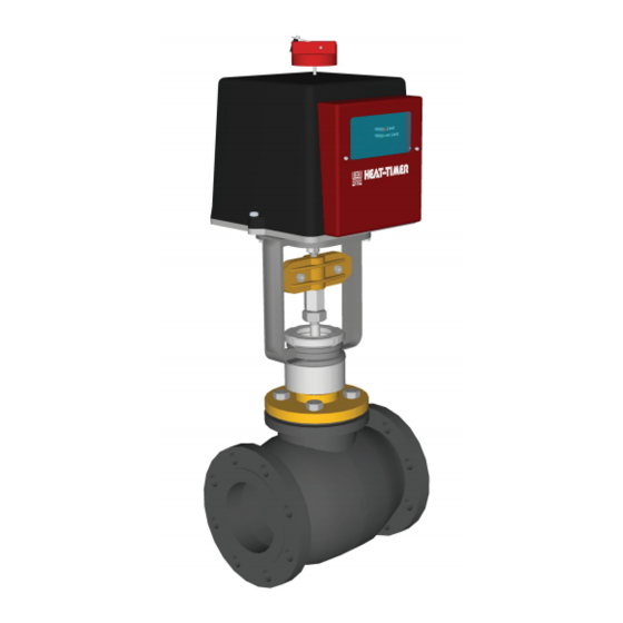
installation and Operation Manual
2-Way Motorized Valves
for Vacuum and Subatmospheric Steam Heating Systems
All Heat-Timer controls and valves are strictly operating controls and
valves; they should never be used as a primary limit or safety control. All
equipment must have its own certified limit and safety controls required
by local codes. The installer must verify proper operation and correct any
safety problems prior to the installation of any Heat-Timer equipment.
with Feedback
Warning
Advertisement
Table of Contents

Subscribe to Our Youtube Channel
Related Manuals for heat-timer 928051-50-VM


Summary of Contents for heat-timer 928051-50-VM
- Page 1 Vacuum and Subatmospheric Steam Heating Systems Warning All Heat-Timer controls and valves are strictly operating controls and valves; they should never be used as a primary limit or safety control. All equipment must have its own certified limit and safety controls required by local codes.
-
Page 2: Installation
Heating applications The 2-Way Floating Motorized Valves are used to modulate or turn on or off the vacuum (subatmospheric steam) to a building or process applications. They are used with Heat-Timer steam heating controls (MPC Platinum and SRC Platinum controls). - Page 3 Mounting alignment • T o avoid valve problems, all dirt, metal shavings, and debris inside the piping must be removed or flushed out prior to installing the valve. • T he preferred installation position of the valve and actuator is upright. However, where space restrictions dictate, the valve assembly can be mounted diagonally. • T he installation should account for an additional clearance of 4 to 6” above the actuator. This space is needed for the manual operation of the actuator. See "Actuator Manual Operation" on page 4. Warning Motorized Valves MUST NOT be installed upside down or horizontally. Warranty is void if valve installation position was installed incorrectly. Valve actuator assembly • F or smaller valves, it is usually easier to assemble the valve and actuator before the installation of the valve on...
- Page 4 • T urn the Crank Handle counter-clockwise to move the Actuator Shaft up (Open Valve). 1) turn power switch Off Wiring • T he Heat-Timer Motorized Valve can be used with virtually any floating motor controller. However, it is designed to work with Heat-Timer controls. • T he actuator/motor uses a floating type signal (R. W. B.). • T he actuator must be powered using the provided 24 VAC transformer. A single transformer can only power a single actuator. The transformer is supplied with every complete valve package. • R emove the Red Actuator cover to reveal the wiring terminals.
- Page 5 2-Way Motorized Valve with Feedback installation Manual...
-
Page 6: Valve Dimensions
2-Way single-seat Motorized Valve Flow Dimensions Medium Valve catalog Coefficient Mount Body trim shipping temp size number Weight range °F 1 ½” 928051-50-VM 19” Bronze 32 to 400 5 ¾ 3 ¼ S. Steel 2” 928052-00-VM 6 ½“ 3 ⅝ ” 19 ¼” Bronze 32 to 400 S. Steel 2 ½” 928052-50-VM 9”... -
Page 7: Warranty
Heat-timer corporation shall not be responsible for any maladjustments of any control installed by Heat-timer corporation. it is the users responsibility to adjust the settings of the control to provide the proper amount of heat or cooling required in the premises and for proper operation of the heating or cooling system. - Page 8 ........(1 ½” -2” Valves) +32ºF to 400ºF Temperature: (2 ½” - 10” Valves) +32ºF to 350ºF 20 New Dutch Lane, Fairfield, NJ 07004 Ph: (973) 575-4004 • Fax: (973) 575-4052 http://www.heat-timer.com...
Need help?
Do you have a question about the 928051-50-VM and is the answer not in the manual?
Questions and answers