Table of Contents
Advertisement
Quick Links
InstallatIon and operatIon InstructIons
Mini-Mod & Mini-Mod extension
sequencIng ModulatIng control
for HydronIc HeatIng systeMs
E
G
ENCLOSED
ENERGY
I
MANAGEMENT
EQUIPMENT
99RA
Comm
ENCLOSED
ENERGY
MANAGEMENT
EQUIPMENT
99RA
PWR
E
K
F
L
G
M
H
N
I
O
J
L N
1 2
3 4
5 6
7 8
9 10
11 12
13 14
the Mini-Mod is strictly an operating control. It cannot be used as a limit control. all
boilers must have all safety and limit controls required by code. It is the responsibility
of the installer to verify that all the safety and limits are working properly.
Extension Module
Full Modulation Sequencing Extension
K
F
L
OUTPUT RATINGS:
120VAC, 6A RESISTIVE
1A PILOT DUTY, 15A TOTAL
M
H
N
FOR ALL CIRCUITS
INPUT RATINGS:
O
J
P
115VAC 60Hz, 12VA MAX
Use Copper Conductors Only.
Power
CAUTION:
Risk of Electric Shock.
More than one disconnect switch may be required
to de-energize the equipment before servicing.
Ext A
Ext B
E
K
F
L
G
M
H
N
I
O
J
P
P
CUR / VLT
CUR / VLT
CUR / VLT
CUR / VLT
CUR / VLT
CUR / VLT
GND
mA
VLT
GND
GND
mA
VLT
GND
GND
mA
VLT
GND
GND
mA
VLT
GND
mA
VLT
GND
GND
mA
15
16
17
18
16
19
20
19
21
22
23
22
24
25
26
27
28
29
30
16
31
WarnIng
this control must be installed by a licensed electrician.
OUTPUT RATINGS:
120VAC, 6A RESISTIVE
1A PILOT DUTY, 15A TOTAL
FOR ALL CIRCUITS
INPUT RATINGS:
115VAC 60Hz , 12VA MAX
USE COPPER CONDUCTORS ONLY
ENCLOSED
ENERGY
CAUTION
: RISK OF ELECTRIC SHOCK
MANAGEMENT
More than one disconnect switch may be required
EQUIPMENT
to de-energize the equipment before servicing.
99RA
PROGRAM
EXTENSION
MODULE
VLT
RS-485
32
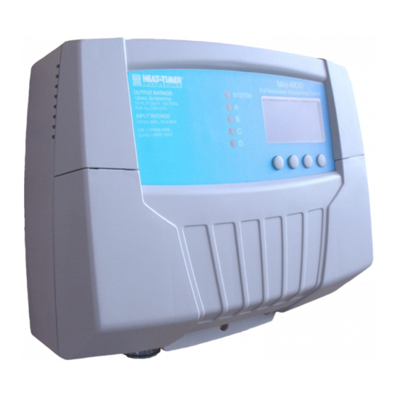
Mini-MOD
Full Modulation Sequencing Control
SYSTEM
A
B
C
D
DO NOT APPLY ANY VOLTAGE
RUN
TO INPUT TERMINALS
Advertisement
Table of Contents

Related Manuals for heat-timer Mini-MOD


Summary of Contents for heat-timer Mini-MOD
- Page 1 13 14 WarnIng the Mini-Mod is strictly an operating control. It cannot be used as a limit control. all boilers must have all safety and limit controls required by code. It is the responsibility of the installer to verify that all the safety and limits are working properly.
-
Page 2: Table Of Contents
... 36 Setting the Control to Factory Defaults . . . 19 Mini-MOD Extension Specifications ..36 Operating Settings ....20... -
Page 3: Mini-Mod Overview
Rotating the first stage to be activated on a call for output promotes even wear on each stage. The Mini-MOD has three modes of rotation: Manual, Last On, or Time. The Time rotates the lead stage every selected time period from every hour to every 60 days. -
Page 4: Modulating Logic Overview
When the Mini-MOD PID requires reduced output, it will reduce the modulation of the lag boiler until it reaches its Ignition %. That shall be followed by the reduction of modulation of the lead boiler until it reaches 40% percent of the Modulation Start %. This shall trigger the control to turn off the lag boiler. -
Page 5: Understanding Operation Concept
1:1.25 its stages to achieve an adjustable fixed Set Point. In Outdoor Reset, the Mini-MOD controls a hot water heating system to provide a building with comfortable and even heat levels. The Mini-MOD varies the temperature of the circulating 1.25:1 heating water in response to changes in the outdoor temperature. -
Page 6: Mini-Mod Layout
Each is wired in series Sensors, no Polarity is observed. with each boiler's limit circuit. Prove terminals must be connected for Mini-Mod to operate boilers. System Output controls Four modulation outputs can be 0-5V, Connect Extension panels to pumps, valves, or other 0-10V, 1-5V, 2-10V, or 4-20ma. -
Page 7: Mini-Mod-Extension Layout
Mini-MOD & Mini-Extension Installation Manual MInI-Mod-extensIon layout Extension Selection Switch to determine Stage letters and LED colors. Ext-A Stages E - J and all LEDs are Green Ext-B Stages K - P and all LEDs are Red LED indicates the This switch is covered with the Wiring Enclosure. -
Page 8: Make Sure You Have The Right Control
• The Mini-MOD can be configured to control up to 4 modulating boilers. It can control up to 16 boiler stages using a maximum of two Mini-MOD Extension Panels ModulatIon Mode •... -
Page 9: Mounting The Enclosure
• This feature lets the Mini-MOD run the SYS relay for a longer period after the boilers have been turned off. When this relay is used to control a pump, it helps in dissipating the excess heat from the boilers combustion chamber. -
Page 10: Install The Sensors
Mini-Mod is installed. Immersion Sensor alert determining the proper location of the outdoor sensor is very important. the Mini-Mod will base the heat on Well Locknut System Sensor the outdoor temperature information it receives from this location. If the sensor is in the sun, or covered with In Well ice, its reading will be different from the actual outdoor temperature (od). -
Page 11: Wiring
"Shutdown/Tstat/Setback Mode" on page 18.. This will provide the user with a customizable Day/Night Schedule. See "Day/Night Schedules" on page 25.. • The Shutdown feature can be used whenever it is desirable to turn off the Mini-MOD stage outputs from a remote location or another controller (i.e. EMS input). -
Page 12: Wiring The Prove
USE COPPER WIRE, CLASS 1 WIRE ONLY. • If the PROVE input is open on a call, the Mini-MOD will enable only the System Output. All boiler outputs will be off when the PROVE input is open. • A factory-installed jumper provides the System Prove signal. Do not remove the jumper unless it will be replaced by a System Prove signal or use the terminals for DHW call. -
Page 13: Wiring The Boilers
• The Mini-MOD and the Mini-MOD Extension sources 24VDC excitation voltage for the 4-20mA signal. ENCLOSED ENERGY • Wire the (-) from the modulating motor to the boiler terminal on the Mini-MOD marked (GND). That is for boiler MANAGEMENT CAUTION... -
Page 14: Menu Sequence
Heat-Timer Corp. Menu sequence -------- SETTINGS ---- ----- SEASON ----- - OUTDOOR CUTOFF - Season Winter Winter Set Point Summer <System Settings> ▲ ▼ BACK SAVE ▲ ▼ BACK SAVE <Maintenance> <History> Reset <System Startup> ------ SET POINT ---- MINIMUM WATER TEMP... - Page 15 SAVE -- STAGE A TRIM -- Output Trim +0.0 <Prev Stage> alert <Next Stage> To be able to change the Mini-MOD ▲ ▼ SELECT BACK settings the Program/Run Switch must be set to Program. The switch ------- STAGE A -------...
-
Page 16: Connecting Extension Panels
• The Mini-MOD is equipped with a 6-pin phone socket (RS485) to connect to extension panels. The Mini-MOD Extension is equipped with two 6-pin phone sockets to connect to Mini-MOD and an additional Mini-MOD Extension. • Set each Extension to a different letter (EXT-A or EXT-B). The Mini-MOD will assign the stage letters based on the extension letter selected. -
Page 17: Startup Settings
USE COPPER CONDUCTORS ONLY prograM cHange settIngs alert To be able to change the Mini-MOD settings the Program/Run Switch must be set to Program. A good practice after performing The switch is located under the Enclosure Wiring Cover for security. The Enclosure Wiring any Startup menu modifications Cover can be securely closed using a lock. -
Page 18: Modulating Mode
However, a call for DHW will bring the boilers on. • When Setback is selected, the External Signal option will switch the Mini-MOD to Setback mode when terminals 31 and 32 are shorted. This allows an external device or control to provide the setback signal. No scheduling or boost menu options will be... -
Page 19: Boost Mode
Mode • When All-On is selected, the Mini-MOD will turn all boilers On to 100% when the System reads Short or Open and the outdoor temperature is below Outdoor Cutoff. However, when the Outdoor reads Short or Open, the Mini-MOD will try to maintain the Maximum Water Temperature. -
Page 20: Operating Settings
Message Display Line will not display any season information when in Winter. Summer. • When the heating season is over, it is a good practice to switch the Mini-MOD to Summer setting. This will allow DHW calls to operate the boilers when needed. -
Page 21: Outdoor Cutoff Temperature
(Note: The lowest water temperature the Mini-MOD will circulate is 70°F. If the Outdoor Cutoff is turned ON and the Season is set to Winter, the Mini-MOD will circulate at least 70°F water even in the hottest of weather.) In the OFF position, the system pump will always be off and all burner stages will be off. -
Page 22: Maximum Water Temp
-------- GAIN --------- Adjustable from -10 to +10 Default: 0 Button: MENU/<System Settings>/Gain • The Gain adjusts the aggressiveness of the Mini-MOD PID logic. It controls how much ▲ ▼ BACK SAVE modulation is changed when the system temperature is different from the Set Point. -
Page 23: Lead Boiler Rotation
▼ BACK SAVE • When the Mini-MOD activates a boiler, it does not start to calculate its output until the Purge Delay is over. This allows the boiler to fully come online and begin producing output. alert • The Purge Delay helps prevent short cycling of any newly activated burner. Once the burner is activated, it MUST run through the entire Purge Delay period. -
Page 24: Standby Delay
In general, when setting the Run-On consult boiler and pump manufacturer. setback ------ SETBACK ------- Adjustable from 0F°/0C° to 75F°/42C° Default: 0F°/0C° Button: MENU/<System Settings>/<More Settings>/Setback • The Setback feature can be used to provide the Mini-MOD with a lower temperature Set ▲ ▼ BACK SAVE Point when less load is required. -
Page 25: Day/Night Schedules
Button: MENU/<System Settings>/<More Settings>/Day/Night Schedules ▲ ▼ SELECT • The Mini-MOD has two levels of heat. The Day (Normal) level is used when a building is BACK occupied and people are active. • The Night (Setback) level is used when a building is not occupied, or when people are sleeping. -
Page 26: History
F, 10:57Am- Button: MENU/<Histories> The Mini-MOD provides users with a graphical history of the System and Outdoor temperatures for the previous 24 hours. The temperatures are sampled every 12 minutes. That is, readings of both System and Outdoor temperatures are recorded and stored every 12 minutes for the last ▲... -
Page 27: Maintenance
• The display will show a percent that is equal to the Ignition % for the stage in Soft-Off delay. That number will blink for the Soft-Off delay period. • If during the Soft-Off delay period the Mini-Mod needed that stage to turn back on, the stage will be released from the Soft-Off delay and resume normal operation. -
Page 28: Configuration
STAGE MENU dIsplay Messages The Mini-MOD normal display layout reserved the second line for message indications. The following is a list of the most common Message Display Line information: • DHW Call (171˚F) There is a DHW (Domestic Hot Water) call. The Mini-MOD will Raise the system Set Point to the indicated temperature. -
Page 29: Boiler Stage Settings
• The following list describes the MODE options: Auto - The Mini-MOD will control the boiler’s operation to maintain the desired Set Point. Only boilers set to Auto can be Lead boilers. Standby Standby boilers can only be activated when all boilers in Auto have been at 100% modulation for a selectable period of time. -
Page 30: Ignition
However, the Modulation Start % should still be set correctly, because it will be valid when modulation is decreasing. • Heat-Timer suggests that when Parallel is selected as the Modulation Mode (See "Modulating Mode" on page 18.) to set the Modulation percent equal to or slightly higher than double the Ignition %. -
Page 31: Troubleshooting
Incorrect temperature Remove the wires from the sensor terminals. The display should change to read OPEN. If it does not, the Mini-MOD may be damaged. Take an ohm reading across the detached sensor wires. The ohm reading should correspond to the Temperature sensor Table. -
Page 32: Direct Heating Piping Diagram
Building Heating Loop system: The Mini-MOD controls 4 modulating boilers. The boilers are piped in Reverse Return on the primary loop. The System output is controlling the System Pump. Heat-Timer Corp. is aware that each installation is unique. Thus, Heat-Timer Corp. is not responsible for any installation related to any electrical or plumbing diagram generated by Heat-Timer Corp.. -
Page 33: Direct Heating Wiring Diagram
Mini-MOD & Mini-Extension Installation Manual MultIple ModulatIng boIlers dIrect HeatIng WIrIng dIagraM Mini-MOD Full Modulation Sequencing Control SYSTEM OUTPUT RATINGS: 4-20ma Modulating 120VAC, 6A RESISTIVE 1A PILOT DUTY, 15A TOTAL FOR ALL CIRCUITS INPUT RATINGS: outputs 115VAC 60Hz , 30VA MAX USE COPPER WIRE, CLASS 1 WIRE ONLY. -
Page 34: 4-20Ma Ems Interface
Heat-Timer Corp. MultIple ModulatIng boIlers external 4-20Ma set poInt usIng 4-20Ma eMs Interface Mini-MOD Full Modulation Sequencing Control SYSTEM OUTPUT RATINGS: 120VAC, 6A RESISTIVE 1A PILOT DUTY, 15A TOTAL FOR ALL CIRCUITS INPUT RATINGS: 115VAC 60Hz , 30VA MAX USE COPPER WIRE, CLASS 1 WIRE ONLY. -
Page 35: Warranty
WARRANTIES AND LIMITATIONS OF LIABILITY AND DAMAGE: Heat-Timer Corporation warrants that it will replace, or at its option, repair any Heat-Timer Corporation manufactured product or part thereof which is found to be defective in material workmanship within one year from the date of installation only if the warranty registration has been properly filled out and returned within 30 days of the date of installation. -
Page 36: Mini-Mod Specifications
(5) 1 Amp inductive (⅛ HP), 6Amp resistive at 120 VAC 60 Hz, 15 A total for all circuits Add-On Mini-MOD Extension Panels: ....up to two Mini-MOD Extension Panels using RS485 Ignition Point %: .
Need help?
Do you have a question about the Mini-MOD and is the answer not in the manual?
Questions and answers