Table of Contents
Advertisement
Quick Links
Installers and Users Installation
and Operation Manuals
Operates a Modulating Motorized Valve, a
Modulating Boiler, or Multi-Boiler Control
This Heat-Timer control is strictly an operating control; it should never
be used as a primary limit or safety control. All equipment must have its
own certified limit and safety controls required by local codes. The installer
must verify proper operation and correct any safety problems prior to the
installation of this Heat-Timer control.
With Optional BACnet Communication
WARNING
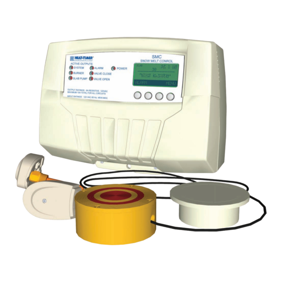
SMC
Snowmelt Control
Advertisement
Table of Contents

Related Manuals for heat-timer SMC


Summary of Contents for heat-timer SMC
- Page 1 With Optional BACnet Communication WARNING This Heat-Timer control is strictly an operating control; it should never be used as a primary limit or safety control. All equipment must have its own certified limit and safety controls required by local codes. The installer must verify proper operation and correct any safety problems prior to the installation of this Heat-Timer control.
-
Page 2: Table Of Contents
Display Unit ..... 23 SMC Controlling a Modulating Water Boiler - Piping . 42 ....23... -
Page 3: Smc Function Chart
Dry-contact inputs. Outdoor Sensor Power modulating valve. System Output operates Boiler or Motorized Valve Connect to the system pump or valve. modulation output signal or 4-20mA BACnet Interface Ext. Interface Set Point. Module SMC Installation and Operation Manual... -
Page 4: Definitions
In Slab Sensor Type mode, the slab sensor base and its conduit must be installed before the slab installation. However, in some sites where the concrete slab is old and cannot be altered, the SMC can operate based on the Outdoor Sensor using the Outdoor Sensor Type mode. This method does not provide any moisture detection and requires the purchase of the optional Outdoor Sensor (HT# 904220-00). -
Page 5: Typical Slab Sensor Mode Installation Steps
• Wire the power to the SMC. But do not power it. See "Wiring the Power" on page 12. • Wire the SMC outputs to the System and Slab Pumps, Motorized Valve, and Boiler. See "Output Wiring" on page 12. - Page 6 (and a heat-exchanger) or a 3-way hydronic mixing motorized valve. Select "Boiler" if the slab loop is heated directly by a modulating boiler. Select "Ext. Interface" if the SMC is connected to a Heat-Timer multi-boiler control (Multi-MOD Platinum, Mini-MOD, SQ-Elite, etc..). Then set the EMS 4 and 20mA set points to match the boiler control 4-20mA set points.
-
Page 7: Typical Outdoor Mode Installation Steps
The higher the Slab ΔT, the more energy is being input to the slab. If the Slab ΔT is set larger than its design ΔT (Max ΔT), the slab itself may be damaged. The SMC provides a Maximum Slab ΔT adjustment. -
Page 8: Typical Snowmelt Piping Configuration
The solution can be heated either directly using a condensing boiler or indirectly using a heat-exchanger. See "SMC Modulating a 3-Way Motorized Valve - Piping" on page 44 and pg 46. In this scenario set the following startup settings: ○... -
Page 9: Installation
INSTALLATION Enclosure Display Module MOUNTING ThE ENCLOSURE The SMC consists of three primary enclosure components. • The Enclosure Display Module: contains the control electronic board, display, buttons, LEDs, and wiring terminals. It has two screws to hold it to the base. -
Page 10: Sensor Installation
Plastic Plug Sensor SLAB SENSOR INSTALLATION Screws (Used Only when Sensor Type is set to Slab) • The supplied Slab Sensor is an integral part of the SMC Slab operation. It provides the SMC with the slab temperature O Ring Sensor and detects precipitation. -
Page 11: Outdoor Sensor Installation
(Used Only when Sensor Type is set to Outdoor) Outdoor Sensor • The SMC does not come with the Outdoor Sensor (HT# 904220- snap-in location 00). It must be ordered separately. See "Outdoor Sensor Operation Overview" on page 6. -
Page 12: Wiring The Power
OUTPUT WIRING WARNING • The SMC outputs do not source any power. If power is needed to a specific Each of the pump relays can output, a separate power source must be wired in series with the output. operate a maximum of ¼ HP •... -
Page 13: Wiring To A Floating Motorized Valve
Terminals (13) through (15) • The SMC is capable of modulating a floating motorized valve. • In this case use the SMC output terminal 14 as the Common. Wire it to the 24 VAC power source (transformer). • Connect the transformer's other wire to the actuator Common terminal. -
Page 14: Wiring To An On/Off Boiler
OUTPUT OUTPUT OUTPUT OUTPUT Terminals (22) and (23) • Wire the boiler or valve (V or +) terminal to the SMC terminal 22 (V+). 20 21 22 23 24 25 20 21 22 23 24 25 • Wire the boiler or valve (-) terminal to the SMC terminal 23 (-). -
Page 15: Wiring Alarm Output To Bms
WIRING ALARM OUTPUT TO BMS Terminals (11) and (12) • The SMC is designed to enable the Alarm output whenever any of the sensors fail or the heating system fails. This output can be connected to a Building management System (BMS) to enable remote alarming and reporting. -
Page 16: Wiring The Outdoor Sensor
3/8 ID well (HT# 904011-00) is required. Both the sensor and well must be purchased separately. See "Boiler Return Sensor" on page 11. • If the Boiler Return Sensor is connected, the SMC will display its temperature during melting and below the ISP temperature. -
Page 17: Wiring The Shutdown / Enable
The System Pump and slab pump relays will remain energized for the Run-On delay period and then turn off. • Bring the two dry contact wires to the SMC 32 and 33 terminals. WIRING ThE PROVE Terminals (34) and (35) •... -
Page 18: Wiring To Bacnet Mstp
WIRING TO BACNET MSTP • For the SMC to communicate over the BACnet MSTP network, the use of the BACnet Interface Module is required. The BACnet Interface Module must be ordered separately (HT# 926781-00). • Connect the provided CAT-5 cable to both the BACnet Interface Module (Product Comm Ethernet port) and the SMC's (RS485 port). -
Page 19: Display And Buttons
DISPLAy AND BUTTONS Display The SMC display layout provides information that gives an immediate picture of the operation status. All the information is brightly displayed. It can be viewed in virtually any light. • Each of the button functions is presented on the bottom of the display. -
Page 20: Display Messages
The SMC closes the valve to increase the boiler return temperature. "Minimum Boiler Return" on page 29. • Hold Idle at 34°F The slab temperature is below the ISP. The SMC modulates the outputs to maintain the slab at 34°F. "Idle Set Point (ISP)" on page 26. • Idle State The slab temperature is between the WWC and the ISP with no precipitation or moisture detected. -
Page 21: System Startup Menus
Boiler Return 142 Warm W.Cutoff 38 F MENU Idle Set Point 34 F ALERT Heating Curve To be able to change the SMC <System Settings> Hold MENU button settings the Program/Run <Maintenance> for 5 seconds Switch must be set to Program. -
Page 22: System Startup
Hold MENU Button: <Settings>/<System Startup>/../Sensor Type outdoor ▲ ▼ • If Slab is selected, the SMC shall use the Slab sensor logic and BACK SAVE measure the slab temperature and detect precipitation. See "Slab Sensor Operation Overview" on page 4. -
Page 23: Display Unit
• The control has a coin Lithium battery (CR2032) (HT# 020002-00) that is used to maintain the control's time during power outages. This battery can maintain the clock for up to a total of 100 days. See "Activate the Battery" on page 18. SMC Installation and Operation Manual... -
Page 24: Bacnet Communication
BACNET COMMUNICATION Available for Installers Only • The SMC control can be configured to communicate over BACnet MSTP. A BACnet Interface Module is required and must be ordered separately (HT# 926781-00). • See "BACnet Variable List" on page 37 BACNET OPTION... -
Page 25: Operating Menus
▼ SELECT BACK PROGRAM SWITCh SETTING DO NOT PROGRAM To be able to change the SMC settings the Program/Run Switch must be set to Program. The switch is located under the Enclosure Wiring Cover for security. SMC Installation and Operation Manual... -
Page 26: Season
• The Season setting controls whether the SMC heats the slab. When set BACK SAVE to Summer, the SMC does not provide any heat to the slab. When set to Winter, the SMC shall heat the slab whenever necessary. • Set the control to Winter mode during the heating season. -
Page 27: Heating Curve Table
• Repeat the above procedure as necessary until the lowest Curve value that still melts the snow is determined. hEATING CURVE TABLE Return Target Temperature based on the Outdoor Temperature and Heating Curve Outdoor Temperature °F SMC Installation and Operation Manual... -
Page 28: System Settings
WWC. • The Minimum Runtime starts a timer once slab heat is activated. The SMC will continue melting until either all the moisture has evaporated off the sensor or until the Minimum Runtime has ended, whichever comes last. -
Page 29: Maximum Delta Temperature (Max ∆T)
(Slab Return) . This is called the Slab ΔT. • If the SMC calculates that the Slab ΔT may exceed the Max ΔT, the SMC will begin closing the slab motorized valve or decreasing the boiler modulation to help prevent excess heat from entering the slab. -
Page 30: Pump Exercise
BACK SAVE period when idling above the ISP or when the SMC is in CWC. It does this to help reduce the possibility of freezing the slab solution. • In addition to having a timed setting the Antifreeze option can be set to ON. -
Page 31: Maintenance Menu
Hold MENU Button: <Settings>/<Maintenance> Boiler Runtime 840hr <Sensors Trim> <Histories> PROGRAM SWITCh SETTING <Configurations> To be able to change the SMC settings the Program/Run Switch must be ▲ ▼ BACK SELECT set to Program. The switch is located under the Enclosure Wiring Cover DO NOT for security. -
Page 32: Boiler Runtime
• The setting adjusts the Slab Sensor's water detection sensitivity. After cleaning the sensor, set the • The Slab Sensor and the SMC are calibrated to detect moisture at the water sensitivity to zero for proper proper level, however Water Sensitivity can be temporarily adjusted to operation. -
Page 33: User Menus
• The Season setting controls whether the SMC heats the slab. When BACK SAVE set to Summer, the SMC does not provide any heat to the slab. When set to Winter, the SMC shall heat the slab whenever necessary. • Set the control to Winter mode during the heating season. -
Page 34: Cold Weather Cutoff (Cwc)
WWC, melting begins. At this point, the WWC will serve as the set point at which the slab temperature will be held. Using the previous example, once a melting cycle has begun, the SMC will maintain the slab at 38° until the moisture is evaporated, or the minimum run time is exceeded, whichever comes last. -
Page 35: Heating Gain
WWC. • The Minimum Runtime starts a timer once slab heat is activated. The SMC will continue melting until either all the moisture has evaporated off the sensor or until the Minimum Runtime has ended, whichever comes last. -
Page 36: Alarms Menu
• The Slab Temperature did not reach its target within 24 hours. See "Troubleshooting" on • Slab Temp. low page 39. • Supply Temp. low • The Slab Supply Temperature did not reach its target within 2 hours. SMC Installation and Operation Manual... -
Page 37: Bacnet Variable List
0 = De-Energized, 1 = Energized 3400 SPUMP Slab Pump Relay 3500 Modulation Output Percent % Modulation (0 - 100%) 3600 TIME Time Minutes Time since midnight(1,2,3…1440) ♦ AV=Analog-Value, BV= Binary-Value, MV=MultiState-Value. Only required BACnet object properties are supported. SMC Installation and Operation Manual... -
Page 38: Bacnet Pics Statement
VENDOR ID ADDRESS AND PhONE 20 New Dutch Ln.Fairfield, NJ 07004 - (973)575-4004 Heat-Timer Corporation PRODUCT DESCRIPTION The SMC is a Snow Melt Control BaCnet Standardized Device Profile (annex l) PRODUCT DEVICE PROFILE BACnet Application Specific Controller (B-ASC) SMC BACnet Control... -
Page 39: Troubleshooting
• Remove the wires from the sensor terminals. The display should change to 42683 read --- or open. If it does not, the SMC may be damaged. Using a multi- 31215 meter set to measure resistance, take an ohm reading across the detached 23089 sensor wires. - Page 40 • The Slab Temperature did not reach its target for a continuous 24 hours: ○ The weather is too cold for the system capability. The SMC is producing heat but may need more time due to extreme temperatures. ○ The heating system may be malfunctioning. Check the heating system components (boiler, pumps, valves).
-
Page 41: Warranty
WARRANTIES AND LIMITATIONS OF LIABILITY AND DAMAGE: Heat-Timer Corporation warrants that it will replace, or at its option, repair any Heat-Timer Corporation manufactured product or part thereof which is found to be defective in material workmanship within one year from the date of installation only if the warranty registration has been properly filled out and returned within 30 days of the date of installation. -
Page 42: Slab Sensor Diagrams
• Control Mode = Boiler ALERT Due to the uniqueness of each installation, Heat-Timer Corp. is not responsible for any installation that is based on any electrical or piping diagram generated. The provided illustrations are to demonstrate the control operating concept only. -
Page 43: Smc Controlling A Modulating Water Boiler - Wiring
SMC CONTROLLING A MODULATING WATER BOILER - WIRING SNOW MELT CONTROL ACTIVE OUTPUTS SLAB SYSTEM ALARM POWER __________________________ BURNER VALVE CLOSE Melting in Progress SLAB PUMP VALVE OPEN ALARM MENU ENCLOSED OUTPUT RATINGS: 6A RESISTIVE, 120VAC ENERGY MAXIMUM 15A TOTAL FOR ALL CIRCUITS... -
Page 44: Smc Modulating A 3-Way Motorized Valve - Piping
• Control Mode = Motorized Valve ALERT Due to the uniqueness of each installation, Heat-Timer Corp. is not responsible for any installation that is based on any electrical or piping diagram generated. The provided illustrations are to demonstrate the control operating concept only. -
Page 45: Smc Modulating A 3-Way Motorized Valve - Wiring
SMC MODULATING A 3-WAy MOTORIzED VALVE - WIRING using Water to Glycol heat-Exchanger and System Pump SNOW MELT CONTROL ACTIVE OUTPUTS SLAB SYSTEM ALARM POWER __________________________ BURNER VALVE CLOSE Melting in Progress Boiler Return = 142 o F SLAB PUMP... -
Page 46: Smc Modulating A 3-Way Motorized Valve - Piping
• Control Mode = Motorized Valve ALERT Due to the uniqueness of each installation, Heat-Timer Corp. is not responsible for any installation that is based on any electrical or piping diagram generated. The provided illustrations are to demonstrate the control operating concept only. -
Page 47: Smc Modulating A 3-Way Motorized Valve - Wiring
SMC MODULATING A 3-WAy MOTORIzED VALVE - WIRING using Water Boiler without a heat-Exchanger SNOW MELT CONTROL ACTIVE OUTPUTS SLAB SYSTEM ALARM POWER __________________________ BURNER VALVE CLOSE Melting in Progress Boiler Return = 142 o F SLAB PUMP VALVE OPEN... -
Page 48: Smc Modulating A 2-Way Motorized Valve - Piping
• Control Mode = Motorized Valve ALERT Due to the uniqueness of each installation, Heat-Timer Corp. is not responsible for any installation that is based on any electrical or piping diagram generated. The provided illustrations are to demonstrate the control operating concept only. -
Page 49: Smc Modulating A 2-Way Motorized Valve - Wiring
SMC MODULATING A 2-WAy MOTORIzED VALVE - WIRING using Steam to Water heat-Exchanger SNOW MELT CONTROL ACTIVE OUTPUTS SLAB SYSTEM ALARM POWER __________________________ BURNER VALVE CLOSE Melting in Progress SLAB PUMP VALVE OPEN ALARM MENU OUTPUT RATINGS: 6A RESISTIVE, 120VAC... -
Page 50: Smc Controlling Multi-Boiler Control - Piping
SMC Installation and Operation Manual... -
Page 51: Smc Controlling Multi-Boiler Control - Wiring
SMC Installation and Operation Manual... -
Page 52: Specifications
..........5 pound 20 New Dutch Lane, Fairfield, NJ 07004 Ph: (973) 575-4004 • Fax: (973) 575-4052 http://www.heat-timer.com SMC Installation and Operation Manual...
Need help?
Do you have a question about the SMC and is the answer not in the manual?
Questions and answers