heat-timer Mini-Extension Installation And Operations
Sequencing modulating control
for hydronic heating systems
Hide thumbs
Also See for Mini-Extension:
- Manual (4 pages) ,
- Installation and operation manual (56 pages)
Table of Contents
Advertisement
Quick Links
INSTALLATION AND OPERATION INSTRUCTIONS
Mini-MOD & Mini-Extension
SEQUENCING MODULATING CONTROL
FOR HYDRONIC HEATING SYSTEMS
Table of Contents
MINI-MOD LAYOUT . . . . . . . . . . . . . 3
MINI-MOD OVERVIEW . . . . . . . . . . . 4
INITIAL SETUP . . . . . . . . . . . . . . . 6
Selecting the System Features. . . . . . . 6
INSTALLATION . . . . . . . . . . . . . . . 7
Mounting the Enclosure . . . . . . . . . . 7
Install the Sensors . . . . . . . . . . . . . 8
Wiring. . . . . . . . . . . . . . . . . . . . 9
MENU SEQUENCE . . . . . . . . . . . . . 12
Startup Settings . . . . . . . . . . . . . . 14
Operating Settings . . . . . . . . . . . . . 16
System Settings . . . . . . . . . . . . . . 18
History . . . . . . . . . . . . . . . . . . . 21
Maintenance . . . . . . . . . . . . . . . . 22
Display . . . . . . . . . . . . . . . . . . . 23
Boiler Stage Settings . . . . . . . . . . . . 24
TROUBLESHOOTING . . . . . . . . . . . . 26
APPLICATION DIAGRAMS . . . . . . . . . 28
SPECIFICATIONS . . . . . . . . . . . . . . 32
The Mini-Mod is strictly an operating control. It CANNOT be used as a limit control. All boilers must have all
safety and limit controls required by code. It is the responsibility of the installer to verify that all the safety and
limits are working properly before the Mini-Mod is installed.
This control must be installed by a licensed electrician.
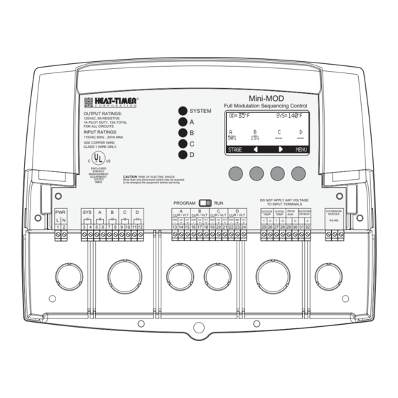
OUTPUT RATINGS:
120VAC, 6A RESISTIVE
1A PILOT DUTY, 15A TOTAL
FOR ALL CIRCUITS
INPUT RATINGS:
115VAC 60Hz , 30VA MAX
USE COPPER WIRE,
CLASS 1 WIRE ONLY.
ENCLOSED
ENERGY
MANAGEMENT
EQUIPMENT
CAUTION
LISTED
More than one disconnect switch may be required
99RA
to de-energize the equipment before servicing.
This manual attempted to be complete and accurate at the time of
publication. Additional upgrades and new features may change Mini-
MOD functions. Upgrades to this manual may occur at any time.
Contact the factory for further details.
WARNING
R
Mini-MOD
Full Modulation Sequencing Control
SYSTEM
A
B
C
D
: RISK OF ELECTRIC SHOCK
DO NOT APPLY ANY VOLTAGE
PROGRAM
RUN
TO INPUT TERMINALS
---
---
Advertisement
Table of Contents

Related Manuals for heat-timer Mini-Extension


Summary of Contents for heat-timer Mini-Extension
-
Page 1: Table Of Contents
INSTALLATION AND OPERATION INSTRUCTIONS Mini-MOD & Mini-Extension SEQUENCING MODULATING CONTROL FOR HYDRONIC HEATING SYSTEMS Table of Contents MINI-MOD LAYOUT ... . . 3 Mini-MOD Full Modulation Sequencing Control SYSTEM OUTPUT RATINGS: MINI-MOD OVERVIEW . - Page 2 Output Trim....22 Connecting to the Mini-Extension Panels . . 11 Configuration ....23 MENU SEQUENCE .
-
Page 3: Mini-Mod Layout
Mini-MOD & Mini-Extension Installation Manual MINI-MOD LAYOUT Program Switch to restrict access to The digital display shows the system status, set point, function changes. This switch is lead stage <in brackets>, and status of each stage. covered with Wiring Enclosure. -
Page 4: Mini-Mod Overview
Heat-Timer Corp. MINI-MOD OVERVIEW SEQUENCES UP TO 4 FULLY MODULATING STAGES. The Mini-MOD is the perfect control whenever multiple fully modulating stages are required for hydronic heating applications. The Mini-MOD controls the on/off and the modulation of each stage to maintain precise system set point control. -
Page 5: Understanding Operation Concept
Mini-MOD & Mini-Extension Installation Manual UNDERSTANDING OPERATION CONCEPT 1:1.5 The Mini-MOD has multiple operating modes that satisfy most hydronic systems. It can 1:1.25 change the System Set Point based on outdoor temperature (Outdoor Reset) or it can modulate its stages to achieve an adjustable fixed Set Point. -
Page 6: Making Sure You Have The Right Control
MAKE SURE YOU HAVE THE RIGHT CONTROL If you need the Mini-MOD to do additional tasks that either are not listed or do not know how to configure them, contact Heat-Timer Corp. Sales Department either by Phone (973)575-4004, Fax (973) 575-4052, or by E-mail support@heat-timer.com. -
Page 7: Installation
INSTALLATION Each of the Mini-MOD or Mini-Extension consists of three primary enclosure components. The Enclosure Display Module: contains the display, buttons, LEDs and electric wiring terminals. It has two screws to hold •... -
Page 8: Install The Sensors
OUTDOOR SENSOR INSTALLATION • Only use the Heat-Timer sensor included with the unit. • Locate the sensor in the shade on the north side of the building. The sensor should never be in direct sunlight. -
Page 9: Wiring
Connect the neutral line to the terminal marked N. • Heat-Timer recommends installing a surge suppressor on the power source to the Mini-MOD. WARNING Class 1 voltages must enter the enclosure through a different opening from any Class 2 voltage wiring. -
Page 10: Wiring The Prove (Terminals 29, 30)
Heat-Timer Corp. WIRING THE PROVE (TERMINALS 29, 30) • The Prove feature is provided to check system component operation and must be selected in the Startup Menu. • A typical use of this feature is to check for flow before firing any boiler. -
Page 11: Wiring To Modulating Motors
• The Mini-MOD is equipped with a 6-pin phone socket to connect to extension panels. • The Mini-Extension is equipped with two 6-pin phone sockets to connect to Mini-MOD and an additional Mini-Extension panel. • Only 6-wire phone cable must be used for proper operation. -
Page 12: Menu Sequence
Heat-Timer Corp. MENU SEQUENCE ----------- SETTINGS ------------ ------------- SEASON -------------- ------- OUTDOOR CUTOFF ------- Season Winter Winter Set Point 70 F Summer <System Settings> <Maintenance> <Histories> <System Startup> BACK SAVE BACK SAVE BACK SELECT ------------ SET POINT ---------- --- MINIMUM WATER TEMP ----... - Page 13 Mini-MOD & Mini-Extension Installation Manual ---- ---- ----- --- GA IN -- ----- ----- -- ---- ----- -- SETT INGS - ----- ----- - Seas on Wint er Set Point 70 F <S ystem S ettin gs> SYSTEM SETTINGS1 <M aint enanc e>...
-
Page 14: Startup Settings
Reset mode is only available if an outdoor sensor is connected to terminals 25 and 26. Reset DO NOT select Reset without an outdoor sensor. • The same Heat-Timer temperature sensor can display in either °F or °C. BACK SAVE •... -
Page 15: Selecting The Modulating Mode
Mini-MOD & Mini-Extension Installation Manual SELECTING THE MODULATING MODE ------ MODULATION MODE ------ Normal Normal, Parallel Default: Normal Parallel Button: MENU/<System Startup>/../Modulating Mode • Some boilers run more efficiently as their modulation increases. For these units, it is more energy efficient to run one unit in high than several units at lower modulation. If your units are of this type, select Normal. -
Page 16: Operating Settings
Heat-Timer Corp. RESET MODE • When All-On is selected, the Mini-MOD will turn all boilers On to a 100% when System reads Short or Open and Outdoor is below Outdoor Cutoff. When Outdoor reads Short or Open, the Mini-MOD will turn all boilers On to a 100%. -
Page 17: Outdoor Cutoff Temperature
Mini-MOD & Mini-Extension Installation Manual will only be 125°F, and at 24°F outside, the system water will be 112°F. Such a low Reset Ratio might be used with radiant floor heating applications. • With most baseboard heating applications, a 1.00 (OD):1.00 (SYS) setting is a good place to start. -
Page 18: System Settings
Heat-Timer Corp. MAXIMUM WATER TEMP --- MAXIMUM WATER TEMP ---- Adjustable 90ºF - 240ºF Default: 240ºF Button: MENU/Set Point/Offset/../Maximum Water Temperature in Reset only • This is the highest temperature heating water the Mini-MOD will circulate through the heating system. It is available in Reset mode only. -
Page 19: Purge Delay
Mini-MOD & Mini-Extension Installation Manual PURGE DELAY --- --- --- PURG E DEL AY -- --- --- - Adjustable 0.0min to 10.0min Default: 1.0min Button: MENU/<System Settings>/Purge Delay • Many boilers go through a purge cycle before they are brought on line. -
Page 20: Setback
Heat-Timer Corp. • A common use for the System Run-On is to control a system pump in a heating system. The extra time helps transfer the heat from the boilers to the heating system. • The System Run-On time should be set based on the size and type of the boilers and pumps. In general, a boiler with low water content and high horsepower will need a longer System Run-On than a boiler with the same horsepower and more water content. -
Page 21: History
Mini-MOD & Mini-Extension Installation Manual read by the Mini-MOD sensor, the Last Stage Hold setting must be accounted for. The boiler limit must be set above the Set Point PLUS the Last Stage Hold PLUS the normal drop experienced in the piping. -
Page 22: Maintenance
Default: 0°F Button: MENU/<Maintenance>/System Trim Button: MENU/<Maintenance>/Outdoor Trim • The Heat-Timer thermistor type sensors are very accurate, and normally require no BAC K SA VE calibration. Sometimes it may be desirable to make small adjustments to the displayed value for either the Outdoor temperature (OD) or the System temperature (SYS). The Trim setting can adjust the displayed value by ±... -
Page 23: Display
Mini-MOD & Mini-Extension Installation Manual -- --- - CO NFI GUR ATIO N 1 - --- -- CONFIGURATION v1 .00 c Button: MENU/<Maintenance>/<Configuration> Re set F • This menu option provides a consolidated view of the Startup settings the Mini-MOD... -
Page 24: Boiler Stage Settings
If a Mini-Extension is connected to the Mini-MOD, scrolling through stages using the the modulation calculation and Next and Prev Stage menu options will scroll through the Mini-Extension stages as well. rotation. That might have dire effects on system response. -
Page 25: Ignition
Mini-MOD & Mini-Extension Installation Manual IGNITION % ------------ STAGE A ------------ IGNITION POINT Adjustable 1% to 50% Default: 1% Button: STAGE/Ignition % • The Ignition Point is the percent of modulation that must be attained before the unit can be activated. -
Page 26: Troubleshooting
Heat-Timer Corp. TROUBLESHOOTING TEMPERATURE INPUTS Temperature Sensor Chart TEMPERATURE Value Display shows Sensor OPEN (in Degrees °F) (in Ohms) Check the sensor is connected and the wires are continuous to the Mini-MOD. Finally follow 117720 the procedure for Incorrect Temperature Display. - Page 27 Mini-MOD & Mini-Extension Installation Manual TROUBLESHOOT - NO HEAT Does the control have Turn control power START power? Is the control in Select WINTER from SUMMER mode? the Season menu. Check the wiring Is the SYSTEM from control to the...
-
Page 28: Application Diagrams
Return on the primary loop. The System output is controlling the System Pump. Heat-Timer Corp. is aware that each installation is unique. Thus, Heat-Timer Corp. is not responsible for any installation related to any electrical or plumbing diagram generated by Heat-Timer Corp.. The provided illustrations are to... - Page 29 Mini-MOD & Mini-Extension Installation Manual MULTIPLE MODULATING BOILERS DIRECT HEATING WIRING DIAGRAM 4-20mA Modulating Outputs Voltage Modulating Outputs...
- Page 30 Heat-Timer Corp. MULTIPLE MODULATING BOILERS EXTERNAL 4-20MA SET POINT USING 4-20MA EMS INTERFACE 4-20mA EMS Interface 4-20 mA EMS 4-20mA INPUT RS485 Signal GND EXTENSION CONNECTORS...
- Page 31 Mini-MOD & Mini-Extension Installation Manual...
-
Page 32: Specifications
(5) 1 Amp inductive, 6Amp resistive at 120 VAC 60 Hz, 15A total for all circuits Add-On Mini-Extension Panels: ..... . . up two Mini-Extension Panels using RS485 Ignition Point %: .
Need help?
Do you have a question about the Mini-Extension and is the answer not in the manual?
Questions and answers