Table of Contents
Advertisement
Quick Links
Advertisement
Table of Contents

Related Manuals for D-Link DES-1210/ME Series


Summary of Contents for D-Link DES-1210/ME Series
- Page 1 DES-1210/ME Series Metro Ethernet Managed Switch Version: 1 00 (Release 20.01)
-
Page 3: Table Of Contents
Table of Contents DES-1210/ME Series Metro Ethernet Managed Switch User Manual Table of Contents Table of Contents ............................. i About This Guide ............................. 1 Terms/Usage ..............................1 Copyright and Trademarks ..........................1 Product Introduction ........................... 2 Switch Description ............................2 Front Panel Description.......................... -
Page 4: Table Of Contents
Table of Contents DES-1210/ME Series Metro Ethernet Managed Switch User Manual System > IPv6 Neighbor Settings ......................20 System > DHCP Auto Configuration ......................21 System > DHCP Auto Image ........................21 System > Port Configuration > Port Settings ................... 21 System >... - Page 5 Table of Contents DES-1210/ME Series Metro Ethernet Managed Switch User Manual Configuration > IGMP Snooping > Host Table ..................48 Configuration > IGMP Snooping > IP Multicast Profile Settings .............. 48 Configuration > IGMP Snooping > Limited Multicast Range Settings ............49 Configuration >...
- Page 6 Table of Contents DES-1210/ME Series Metro Ethernet Managed Switch User Manual Security > CPU Protect ..........................79 Security > ARP Spoofing Prevention ....................... 79 Security > Gratuitous ARP ........................80 Security > Port Security ..........................81 Security > SSL Settings ..........................81 Security >...
- Page 7 Table of Contents DES-1210/ME Series Metro Ethernet Managed Switch User Manual Monitoring > IGMP Snooping > IGMP Snooping Group ................ 111 Monitoring > IGMP Snooping > IGMP Snooping Host ................112 Monitoring > Port Access Control > RADIUS Authentication ..............112 Monitoring >...
-
Page 9: About This Guide
Reproduction in any manner whatsoever without the written permission of D-Link Corporation is strictly forbidden. Trademarks used in this text: D-Link and the D-LINK logo are trademarks of D-Link Corporation; Microsoft and Windows are registered trademarks of Microsoft Corporation. Other trademarks and trade names may be used in this document to refer to either the entities claiming the marks and names or their products. -
Page 10: Product Introduction
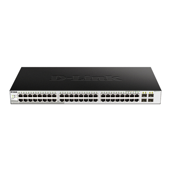
Gigabit Combo Ports Switch Description DES-1210/ME Series is D-Link’s Metro Ethernet Managed switch which provides 48 copper ports (10/100Mbps) and 4 combo Copper/SFP (100/1000Mbps) that can be used to attach various networking devices to the network like Computers, Notebooks, Print Servers, Network Attached Storage devices, IP Cameras, VoIP PBX devices, and other Switches. -
Page 11: Led Indicators
1 Product Introduction DES-1210/ME Series Metro Ethernet Managed Switch User Manual LED Indicators The Switch supports LED indicators for Power, Console, and Link/Act or Link/Act/Speed for each port. The following shows the LED indicators for the DES-1210-52/ME Metro Ethernet Managed Switch along with an explanation of each indicator. -
Page 12: Rear Panel Description
1 Product Introduction DES-1210/ME Series Metro Ethernet Managed Switch User Manual When there is a secure 100Mbps Solid Light Ethernet connection (or link) at any of the ports. Amber When there is reception or transmission (i.e. Activity—Act) of Blinking data occurring at a 100Mbps Ethernet connected port. - Page 13 1 Product Introduction DES-1210/ME Series Metro Ethernet Managed Switch User Manual Figure 1.5 - Inserting the SFP modules into the Switch Figure 1.6 - Installing the SFP Module The Switch is equipped with SFP ports, which are to be used with fiber-optical transceiver cabling in order to uplink various other networking devices for a gigabit link that may span great distances.
-
Page 14: Hardware Installation
DES-1210/ME Series Metro Ethernet Managed Switch User Manual Hardware Installation This chapter provides unpacking and installation information for the D-Link Metro Ethernet Switch. Safety Cautions To reduce the risk of bodily injury, electrical shock, fire and damage to the equipment, observe the following precautions: ... -
Page 15: Step 1: Unpacking
2 Hardware Installation DES-1210/ME Series Metro Ethernet Managed Switch User Manual When connecting or disconnecting power to hot-pluggable power supplies, if offered with your system, observe the following guidelines: Install the power supply before connecting the power cable to the power supply. -
Page 16: Step 3 - Plugging In The Ac Power Cord
2 Hardware Installation DES-1210/ME Series Metro Ethernet Managed Switch User Manual Figure 2.2 – Attach the mounting brackets to the Switch Then, use the screws provided with the equipment rack to mount the switch in the rack. Figure 2.3 – Mount the Switch in the rack or chassis... -
Page 17: Power Failure
As a precaution, the switch should be unplugged in case of power failure. When power is resumed, plug the switch back in. Grounding the Switch This section describes how to connect the DES-1210/ME Series Switch to ground. You must complete this procedure before powering your switch. Required Tools and Equipment ... -
Page 18: Introduction To Switch Managemant
This chapter introduces the management interface of D-Link Metro Ethernet Switch. Management Options The D-Link Metro Ethernet Switch can be managed out-of-band through the console port on the front panel or in-band using Telnet. The user may also choose the Web-based management, accessible through a web browser. -
Page 19: Web-Based Management
D-Link smart switches and D-Link Discover Protocol (DDP) supported devices (for a list of supported models, refer to the D-Link Network Assistant (DNA) User Guide), that are in the same subnet as the PC, collect traps and log messages, and provide quick access to basic configurations of the switch. -
Page 20: Configuration
Logout button first, then it will be seen as an abnormal exit and the login session will still be occupied. Finally, by clicking on the D-Link logo at the upper-left corner of the screen you will be redirected to the local D-Link website. -
Page 21: Tool Bar > Save Menu
4 Configuration DES-1210/ME Series Metro Ethernet Managed Switch User Manual Tool Bar > Save Menu The Save Menu provides Save Configuration and Save Log functions. Figure 4.2 – Save Menu Save Configuration Select to save the entire configuration changes you have made of the device to switch’s non-volatile RAM then click Save Config button to take effect. -
Page 22: Reboot Device
4 Configuration DES-1210/ME Series Metro Ethernet Managed Switch User Manual Reboot Device Provide a safe way to reboot the system. Click Reboot to restart the switch. Figure 4.7 – Tool Menu > Reboot Device Configuration Backup & Restore Allow the current configuration settings to be saved to a file (not including the password), and if necessary, you can restore configuration settings from this file. -
Page 23: Firmware Backup & Upgrade
4 Configuration DES-1210/ME Series Metro Ethernet Managed Switch User Manual FTP password: Enter the password which you want to save/restore from for the configuration. FTP Port: Enter the port which you want to save/restore from for the FTP server. FTP Path: Enter the path which you want to save/restore from for the FTP server. -
Page 24: Tool Bar > Online Help
The Online Help provides two ways of online support: Figure 4.10 – Online Help D-Link Support Site: This will lead you to the D-Link website where you can find online resources such as updated firmware images. User Guide: This can offer an immediate reference for the feature definition or configuration guide. -
Page 25: System > System Settings
4 Configuration DES-1210/ME Series Metro Ethernet Managed Switch User Manual It also offers an overall status of common software features: STP: Click Settings to link to Configuration > Spanning Tree > STP Bridge Global Settings. Default is disabled. Port Mirroring: Click Settings to link to Configuration > Port Mirroring. Default is disabled. -
Page 26: System > Firmware Information
4 Configuration DES-1210/ME Series Metro Ethernet Managed Switch User Manual Figure 4.13 – System > System Settings System > Firmware Information The Firmware Information page displays the information of firmware. The user can specify configuration and image file to boot up when power on the Switch next time. -
Page 27: System > Ip Interface
4 Configuration DES-1210/ME Series Metro Ethernet Managed Switch User Manual Baud Rate: Set the serial bit rate used to communicate with a management station. The console baud rate is 9600 bits per seconds. Auto Logout: This sets the time the interface can be idle before the seitch automatically logs-out the user. -
Page 28: System > Ipv6 Route Settings
4 Configuration DES-1210/ME Series Metro Ethernet Managed Switch User Manual NS Retransmit Time Settings: NS Retransmit Time (1-3600): Enter the Neighbor solicitation’s retransmit timer in second here. Specifies the NS retransmit time for IPv6. The field range is 1-3600, and default is 1 second. -
Page 29: System > Dhcp Auto Configuration
4 Configuration DES-1210/ME Series Metro Ethernet Managed Switch User Manual State: Use the drop-down menu to select All, Address, Static or Dynamic. When the user selects address from the drop-down menu, the user will be able to enter an IP address in the space provided next to the state option. -
Page 30: System > Port Configuration > Port Description
4 Configuration DES-1210/ME Series Metro Ethernet Managed Switch User Manual State: Enable or disable the state of specified ports. Speed: Gigabit Fiber connections can operate in 1000M Full Force Mode, Auto Mode or Disabled. Copper connections can operate in Forced Mode settings (1000M Full, 100M Full, 100M Half, 10M Full, 10M Half), Auto, or Disabled. -
Page 31: System > Port Configuration > Port Media Type
4 Configuration DES-1210/ME Series Metro Ethernet Managed Switch User Manual Connection Status: This field will read the uplink status of the individual ports, whether Enabled or Disabled. Reason: Describes the reason why the port has been error-disabled, such as a STP loopback occurrence. -
Page 32: System > Snmp Settings > Snmp Group Table
4 Configuration DES-1210/ME Series Metro Ethernet Managed Switch User Manual Figure 4.27 – System > SNMP Settings > SNMP User Table User Name: Enter a SNMP user name of up to 32 characters. Group Name: Specify the SNMP group of the SNMP user. -
Page 33: System > Snmp Settings > Snmp Community Table
4 Configuration DES-1210/ME Series Metro Ethernet Managed Switch User Manual Figure 4.29 – System > SNMP Settings > SNMP View Table View Name: Name of the view, up to 32 characters. Subtree OID: The Object Identifier (OID) Subtree for the view. The OID identifies an object tree (MIB tree) that will be included or excluded from access by an SNMP manager. -
Page 34: System > Snmp Settings > Snmp Engine Id
4 Configuration DES-1210/ME Series Metro Ethernet Managed Switch User Manual Figure 4.31– System > SNMP Settings > SNMP Host Table Click Apply to create a new SNMP host, Delete to remove an existing host. System > SNMP Settings > SNMP Engine ID The Engine ID is a unique identifier used to identify the SNMPv3 engine on the Switch. -
Page 35: System > User Accounts
4 Configuration DES-1210/ME Series Metro Ethernet Managed Switch User Manual Port Security Violation: Information of Port Security Violation. IMPB Violation: IMPB Violation information. Loopback Detection occurring / recovery: Specify the device to send SNMP Trap when Loopback Detection occurring and recovery. -
Page 36: System > Pppoe Circuit Id Insertion Settings
4 Configuration DES-1210/ME Series Metro Ethernet Managed Switch User Manual Figure 4.36 – System > ARP Aging Time Settings ARP Aging Time (0-65535): Specifies the ARP aging time on the Switch. The range is from 0 to 65535 with a default setting of 5 minutes. -
Page 37: System > Telnet Settings
4 Configuration DES-1210/ME Series Metro Ethernet Managed Switch User Manual Figure 4.38– System > Web Settings Port (1-65535): Specifies the Port number. The range is between 1 and 65535 with the well-known default is System > Telnet Settings Telnet configuration is Enabled by default. If user does not want to allow the Telnet configuration, they only need to disable the Telnet State. -
Page 38: System > Mac Notification Settings
4 Configuration DES-1210/ME Series Metro Ethernet Managed Switch User Manual System > MAC Notification Settings MAC Notification page is used to monitor MAC addresses learned and entered into the forwarding database. To globally set MAC notification on the Switch, user should enabled or disabled state, input the Time Interval between notification and History Size then click the Apply button. -
Page 39: System > System Log Configuration > System Log Server
4 Configuration DES-1210/ME Series Metro Ethernet Managed Switch User Manual System > System Log Configuration > System Log Server The user can send Syslog messages to up to four designated servers using the System Log Server. It supports maximum 500 system log entries. To set the System Log Server configuration, click Apply. -
Page 40: System > Power Saving
4 Configuration DES-1210/ME Series Metro Ethernet Managed Switch User Manual NOTE: The time must be set after current time, otherwise it will take effect on the next cycle time. System > Power Saving The Power Saving mode feature reduces power consumption automatically when the RJ-45 port is link down or the connected devices are turned off. -
Page 41: System > Smtp Service > Smtp Server Settings
4 Configuration DES-1210/ME Series Metro Ethernet Managed Switch User Manual Figure 4.47 – System > IEEE802.3az EEE Settings From Port / To Port: A consecutive group of ports may be configured starting with the selected port. State: Enabled or Disabled the IEEE802.3az EEE for the specified ports. By default, all ports are enabled. -
Page 42: System > Smtp Service > Smtp Service
Once the message is ready, click Send to send this mail to all recipients configured on the Switch for SMTP. System > D-Link Discover Protocol Settings For the D-Link Discovery Protocol (DDP) supported device, this page is an option for you to disable DDP or configure the DDP packet report timer. -
Page 43: Configuration > 802.1Q Vlan
4 Configuration DES-1210/ME Series Metro Ethernet Managed Switch User Manual larger payloads per packet. The Jumbo Frame page allows network managers to enable Jumbo Frames on the device. The Jumbo Frame default is disabled, Select Enabled then click Apply to turn on the jumbo frame support. - Page 44 4 Configuration DES-1210/ME Series Metro Ethernet Managed Switch User Manual Figure 4.53 – Configuration > 802.1Q VLAN > Add VLAN After click Apply, the 802.1Q VLAN Configuration Table will displayed with updates. Figure 4.54 - Configuration > 802.1Q VLAN > Example VIDs Click the VID number, the configuration of VLAN group which selected by user will displayed.
-
Page 45: Configuration > Vlan Status
4 Configuration DES-1210/ME Series Metro Ethernet Managed Switch User Manual Figure 4.56 - Configuration > 802.1Q VLAN > VID Assignments Configuration > VLAN Status The VLAN Status page is for user to search the VLAN which has already existed on the Switch. -
Page 46: Configuration > Gvrp Settings
4 Configuration DES-1210/ME Series Metro Ethernet Managed Switch User Manual Configuration > GVRP Settings The GVRP Settings page allows user to determine whether the Switch will share its VLAN configuration information with other GARP VLAN Registration Protocol (GVRP) enabled switches. In addition, Ingress Checking can be used to limit traffic by filtering incoming packets whose PVID does not match the PVID of the port. -
Page 47: Configuration > Qinq > Qinq Settings
4 Configuration DES-1210/ME Series Metro Ethernet Managed Switch User Manual Figure 4.60 - Configuration >GVRP Timer Settings Join Time (100-100000): Indicates the time in milliseconds that PDUs are transmitted. The default value is 200ms. Leave Time (100-100000): Indicates the amount of time in milliseconds that the device waits before leaving its GARP state. -
Page 48: Configuration > Qinq > Vlan Translation Cvid Entry Settings
4 Configuration DES-1210/ME Series Metro Ethernet Managed Switch User Manual NNI – To select a network-to-network interface specifies that communication between two specified networks will occur. Outer TPID (hex: 0x1-0xffff): The Outer TPID is used for learning and switching packets. The Outer TPID constructs and inserts the outer tag into the packet based on the VLAN ID and Inner Priority. -
Page 49: Configuration > 802.1V Protocol Vlan > 802.1V Protocol Vlan Settings
4 Configuration DES-1210/ME Series Metro Ethernet Managed Switch User Manual Figure 4.63 - Configuration > 802.1v Protocol VLAN > 802.1v Protocol Group Settings Group ID (1-16): Select an ID number for the group. The value is between 1 and 16. -
Page 50: Configuration > Vlan Trunk Settings
4 Configuration DES-1210/ME Series Metro Ethernet Managed Switch User Manual Configuration > VLAN Trunk Settings The VLAN Trunk Settings is used to combine a number of VLAN ports together to create VLAN trunks. To create VLAN Trunk Port settings on the Switch, enter the ports to be configured, change the state to Enabled and click Apply, the new settings will appear in the VLAN Trunk Port Settings Table below. -
Page 51: Configuration > Link Aggregation > Lacp Port Settings
4 Configuration DES-1210/ME Series Metro Ethernet Managed Switch User Manual Configuration > Link Aggregation > LACP Port Settings The LACP Port Settings is used to create port trunking groups on the Switch. The user may set which ports will be active and passive in processing and sending LACP control frames. -
Page 52: Configuration > Igmp Snooping > Igmp Snooping
4 Configuration DES-1210/ME Series Metro Ethernet Managed Switch User Manual Figure 4.68 – Configuration > BPDU Protection Settings Trap Status: Specify to send trap packet when Attack Detected, Attack Cleared, None or Both. Log Status: Specify the Log Status when Attack Detected, Attack Cleared, None or Both. - Page 53 4 Configuration DES-1210/ME Series Metro Ethernet Managed Switch User Manual Figure 4.69 – Configuration > IGMP Snooping > IGMP Snooping By default, IGMP is disabled. If enabled, the IGMP Global Settings will need to be entered: Host Timeout (130-153025 sec): This is the interval after which a learned host port entry will be purged. For each host port learned, a 'Port Purge Timer' runs for 'Host Port Purge Interval'.
-
Page 54: Configuration > Igmp Snooping > Igmp Access Control Settings
4 Configuration DES-1210/ME Series Metro Ethernet Managed Switch User Manual the moment the last host leaves a group and when the multicast server is notified that there are no more members. It also allows adjustments for controlling the frequency of IGMP traffic on a subnet. Default is 10 seconds. -
Page 55: Configuration > Igmp Snooping > Ism Vlan Settings
4 Configuration DES-1210/ME Series Metro Ethernet Managed Switch User Manual Figure 4.73 – Configuration > IGMP Snooping > IGMP Access Control Settings From Port/To Port: Select the port ranges to be configured. Status: Enable or disable the IGMP Access Control of specified ports. -
Page 56: Configuration > Igmp Snooping > Host Table
4 Configuration DES-1210/ME Series Metro Ethernet Managed Switch User Manual Member Ports: Enter a port or list of ports to be added to the Multicast VLAN. Member ports shall be the untagged members of the multicast VLAN. Tagged Member Ports: Enter a port or list of ports that will become tagged members of the Multicast VLAN. -
Page 57: Configuration > Igmp Snooping > Limited Multicast Range Settings
4 Configuration DES-1210/ME Series Metro Ethernet Managed Switch User Manual Figure 4.77 - Configuration > IGMP Snooping > IP Multicast Profile Settings Profile Type: Specify the profile type to be IPv4 or IPv6. Profile ID: Specify the Profile ID. Profile Name: Specify the Profile Name. -
Page 58: Configuration > Mld Snooping > Mld Snooping Settings
4 Configuration DES-1210/ME Series Metro Ethernet Managed Switch User Manual Figure 4.79- Configuration > IGMP Snooping > Max Multicast Group Settings From Port / To Port: Specify the port ranges to be configured. IP Type: Specify the IP type is IPv4 or IPv6. - Page 59 4 Configuration DES-1210/ME Series Metro Ethernet Managed Switch User Manual Click Apply to implement changes made. Click MLDEdit button to enter the MLD Parameters Settings page, and the parameters to be configured in the following page. Figure 4.81 – Configuration > MLD Snooping > MLD Snooping – MLDEdit page Robustness Variable (2-255): The Robustness Variable allows adjustment for the expected packet loss on a subnet.
-
Page 60: Configuration > Mld Snooping > Mld Host Table
4 Configuration DES-1210/ME Series Metro Ethernet Managed Switch User Manual Figure 4.82 – Configuration > MLD Snooping > MLD Snooping-Router Port Settings To view the Multicast Entry Table for a given VLAN, press the View button. Figure 4.83 – Configuration > IGMP Snooping > IGMP Snooping-Multicast Entry Table Router Timeout (60-600): Specifies the time interval in seconds the Multicast router waits to receive a message before it times out. -
Page 61: Configuration > Port Mirroring
4 Configuration DES-1210/ME Series Metro Ethernet Managed Switch User Manual Figure 4.84 - Configuration > MLD Snooping > MLD Host Table Configuration > Port Mirroring Port Mirroring is a method of monitoring network traffic that forwards a copy of each incoming and/or outgoing packet from one port of the Switch to another port, where the packet can be studied. -
Page 62: Configuration > Sntp Settings > Time Settings
4 Configuration DES-1210/ME Series Metro Ethernet Managed Switch User Manual Figure 4.86 – Configuration > Loopback Detection Loopback Detection State: Use the drop-down menu to enable or disable loopback detection. The default is Disabled. Mode: Specify the Loopback Detection to be Port-based or VLAN-based. -
Page 63: Configuration > Sntp Settings > Timezone Settings
4 Configuration DES-1210/ME Series Metro Ethernet Managed Switch User Manual If choosing SNTP for the clock source, then the following parameters will be available: SNTP First Server: Select IPv4 or IPv6 and specify the IP address of the primary SNTP server from which the system time is retrieved. -
Page 64: Configuration > Dhcp/Bootp Relay > Dhcp/Bootp Relay Global Settings
4 Configuration DES-1210/ME Series Metro Ethernet Managed Switch User Manual To: Which Week of the Month Month / Day of the Week: Enter the month DST and date DST will end on, each year. To: Time in HH MM: Enter the time of day that DST will end on, each year. -
Page 65: Configuration > Dhcp/Bootp Relay > Dhcp/Bootp Relay Interface Settings
4 Configuration DES-1210/ME Series Metro Ethernet Managed Switch User Manual relayed to the server by the relay agent. The switch verifies that it originally inserted the option 82 data. Finally, the relay agent removes the option 82 field and forwards the packet to the switch port that connects to the DHCP client that sent the DHCP request. -
Page 66: Configuration > Dhcp Local Relay Settings
4 Configuration DES-1210/ME Series Metro Ethernet Managed Switch User Manual Figure 4.90 - Configuration > DHCP/BOOTP Relay > DHCP/BOOTP Relay Interface Settings Interface: The IP interface on the Switch that will be connected directly to the Server. Server IP: Enter the IP address of the DHCP/BOOTP server. Up to four server IPs can be configured per IP Interface. -
Page 67: Configuration > Dhcpv6 Relay Option38 Settings
4 Configuration DES-1210/ME Series Metro Ethernet Managed Switch User Manual DHCPv6 Relay Hops Count Limit (1-32): The field allows and entry between 1 and 32 to define the maximum number of router hops DHCPv6 messages can be forwarded. The default hop count is 4. - Page 68 4 Configuration DES-1210/ME Series Metro Ethernet Managed Switch User Manual The IEEE 802.1w Rapid Spanning Tree Protocol (RSTP) evolved from the 802.1D STP standard. RSTP was developed in order to overcome some limitations of STP that impede the function of some recent switching innovations.
-
Page 69: Configuration > Spanning Tree > Stp Port Settings
4 Configuration DES-1210/ME Series Metro Ethernet Managed Switch User Manual Hello Time (1-10 sec): The user may set the time interval between transmissions of configuration messages by the root device, thus stating that the Switch is still functioning. The default is 2 seconds. -
Page 70: Configuration > Spanning Tree > Mst Configuration Identification
4 Configuration DES-1210/ME Series Metro Ethernet Managed Switch User Manual 0 (auto) - Setting 0 for the external cost will automatically set the speed for forwarding packets to the specified port(s) in the list for optimal efficiency. Default port cost: 100Mbps port = 200000. Gigabit port = 20000. -
Page 71: Configuration > Spanning Tree > Stp Instance Settings
4 Configuration DES-1210/ME Series Metro Ethernet Managed Switch User Manual Figure 4.96 - Configuration > Spanning Tree > MST Configuration Identification MST Configuration Identification Settings: Configuration Name: A previously configured name set on the Switch to uniquely identify the MSTI (Multiple Spanning Tree Instance). -
Page 72: Configuration > Ethernet Oam > Ethernet Oam Port Settings
4 Configuration DES-1210/ME Series Metro Ethernet Managed Switch User Manual Figure 4.98 - Configuration > Spanning Tree > MST Port Information Instance ID: Displays the MSTI ID of the instance being configured. An entry of 0 in this field denotes the CIST (default MSTI). -
Page 73: Configuration > Ethernet Oam > Ethernet Oam Event Configuration
4 Configuration DES-1210/ME Series Metro Ethernet Managed Switch User Manual Ignore – Select to ignore the received Ethernet OAM remote loopback command. Click Apply to take effect. Configuration > Ethernet OAM > Ethernet OAM Event Configuration The Ethernet OAM Event Configuration page allows user to configure the Ethernet OAM configuration settings. -
Page 74: Configuration > Ddm > Ddm Temperature Threshold Settings
4 Configuration DES-1210/ME Series Metro Ethernet Managed Switch User Manual Power Unit: Specifies the power unit for DDM. The options are mW (milliwatts) and dBm (decibel-milliwatts). From Port / To Port: Specifies a port or range of ports to be configured. -
Page 75: Configuration > Ddm > Ddm Bias Current Threshold Settings
4 Configuration DES-1210/ME Series Metro Ethernet Managed Switch User Manual High Alarm: Specifies the high threshold for the alarm. When the operating Voltage rises above the configured value, the action associated with the alarm is taken. Low Alarm: Specifies the low threshold for the alarm. When the operating Voltage falls below the configured value, the action associated with the alarm is taken. -
Page 76: Configuration > Ddm > Ddm Rx Power Threshold Settings
4 Configuration DES-1210/ME Series Metro Ethernet Managed Switch User Manual Port: Specifies the port to be configured. Type: Specifies the type for the operating parameter, the options are High Alarm, Low Alarm, High Warning and Low Warning. High Alarm: Specifies the high threshold for the alarm. When the TX power threshold rises above the configured value, the action associated with the alarm is taken. -
Page 77: Configuration > Duld > Duld Global Settings
4 Configuration DES-1210/ME Series Metro Ethernet Managed Switch User Manual Figure 4.105 - Configuration > DDM > DDM Status Table Configuration > DULD > DULD Global Settings The DULD Global Settings page allows user to configure the DULD recover time. -
Page 78: Configuration > Multicast Forwarding & Filtering > Multicast Filtering
4 Configuration DES-1210/ME Series Metro Ethernet Managed Switch User Manual Figure 4.108 - Configuration > Multicast Forwarding & Filtering > Multicast Forwarding VID: The VLAN ID of the VLAN to which the corresponding MAC address belongs. Multicast MAC Address: The MAC address of the static source of multicast packets. This must be a multicast MAC address. - Page 79 4 Configuration DES-1210/ME Series Metro Ethernet Managed Switch User Manual Figure 4.110 – QoS > Traffic Control From Port/To Port: A consecutive group of ports may be configured starting with the selected port. Drop Threshold (64Kbps * N): If storm control is enabled (default is disabled), the threshold is from of 64 ~ 1,024,000 Kbit per second, with steps (N) of 64Kbps.
-
Page 80: Qos > Traffic Control
4 Configuration DES-1210/ME Series Metro Ethernet Managed Switch User Manual NOTE: Ports that are in rest mode will be seen as link down in all windows and screens until it enters the auto-recovery mode or the user recovers these ports by configuring the port state. -
Page 81: Qos > Bandwidth Control
4 Configuration DES-1210/ME Series Metro Ethernet Managed Switch User Manual NOTE: Traffic Control cannot be implemented on ports that are set for Link Aggregation. NOTE: Ports that are in the rest mode will be seen as Discarding in Spanning Tree windows and implementations though these ports will still be forwarding BPDUs to the Switch’s CPU. -
Page 82: Qos > Cos Output Scheduling
4 Configuration DES-1210/ME Series Metro Ethernet Managed Switch User Manual Figure 4.113 - QoS > CoS Scheduling Mechanism Strict Priority: Denoting a Strict scheduling will set the highest queue to be emptied first while the other queues will follow the weighted round-robin scheduling scheme WRR: Use the weighted round-robin (WRR) algorithm to handle packets in an even distribution in priority classes of service. -
Page 83: Qos > 802.1P User Priority
4 Configuration DES-1210/ME Series Metro Ethernet Managed Switch User Manual From Port / To Port: A consecutive group of ports may be configured starting with the selected port. Priority: Defines the priority assigned to the port. The priority are 0~7. -
Page 84: Qos > Priority Settings
4 Configuration DES-1210/ME Series Metro Ethernet Managed Switch User Manual From DSCP value / To DSCP value: Specify the range of DSCP values. Class ID: Specify the priority queue for the switch. The value is from 0 to 3. Click Apply to implement changes made. -
Page 85: Rmon > Rmon History Control Configuration
4 Configuration DES-1210/ME Series Metro Ethernet Managed Switch User Manual Index (1 - 65535): Indicates the RMON Ethernet Statistics entry number. Port: Specifies the port from which the RMON information was taken. Owner: Displays the RMON station or user that requested the RMON information. -
Page 86: Rmon > Rmon Event Configuration
4 Configuration DES-1210/ME Series Metro Ethernet Managed Switch User Manual Absolute value – Compares the values directly with the thresholds at the end of the sampling interval. Falling Threshold (0 ~ 2^31-1): Displays the falling counter value that triggers the falling threshold alarm. -
Page 87: Security > Safeguard Engine
To delete the IP address, simply click the Delete button. Check the unwanted address, and then click Apply. Security > Safeguard Engine D-Link’s Safeguard Engine is a robust and innovative technology that automatically throttles the impact of packet flooding into the switch's CPU. This function helps protect the Switch from being interrupted by malicious viruses or worm attacks. -
Page 88: Security > Gratuitous Arp
4 Configuration DES-1210/ME Series Metro Ethernet Managed Switch User Manual ARP to the network claiming to be the gateway, so that the whole network operation is turned down as all packets to the Internet will be directed to the wrong node. -
Page 89: Security > Port Security
4 Configuration DES-1210/ME Series Metro Ethernet Managed Switch User Manual Learn received Gratuitous ARP: This is used to enable/disable updating ARP cache based on the received gratuitous ARP packet. If a switch receives a gratuitous ARP packet and the sender’s IP address in its ARP table, it should update the ARP entry. -
Page 90: Security > Smart Binding > Smart Binding Settings
4 Configuration DES-1210/ME Series Metro Ethernet Managed Switch User Manual This page allows you to configure the SSL global state and the Ciphersuite settings. Select Enable or Disable and then click Apply to change the SSL state or the Ciphersuite settings of the Switch. By default, SSL is Disabled and all Ciphersuites are Enabled. -
Page 91: Security > Smart Binding > Smart Binding
4 Configuration DES-1210/ME Series Metro Ethernet Managed Switch User Manual Figure 4.131 – Security > Smart Binding > Smart Binding Settings The Smart Binding Settings page contains the following fields: From Port/ To Port: Select a range of ports to set for IP-MAC-port binding. -
Page 92: Security > Smart Binding > White List
4 Configuration DES-1210/ME Series Metro Ethernet Managed Switch User Manual Figure 4.132 – Security > Smart Binding > Smart Binding The Manual Binding Settings contains the following fields: IP Address: Specifies the IP address to bind to the MAC address set below. -
Page 93: Security > Smart Binding > Dhcp Snooping List
4 Configuration DES-1210/ME Series Metro Ethernet Managed Switch User Manual Figure 4.134 – Security > Smart Binding > Black List By giving conditions, desired devices information can be screened out below then click Find to search for a list of the entry: VID: Enter the VLAN ID number of the device. -
Page 94: Security > 802.1X > 802.1X User
4 Configuration DES-1210/ME Series Metro Ethernet Managed Switch User Manual By default, 802.1X is disabled. To use EAP for security, select enabled and set the Authentication Mode and Authentication Protocol then click Apply. Authentication Mode: Indicates the 802.1X mode enabled on the device. The possible field values are: Port Based –... -
Page 95: Security > 802.1X > 802.1X Authentication Radius
4 Configuration DES-1210/ME Series Metro Ethernet Managed Switch User Manual Figure 4.137 - Security > 802.1X > 802.1X User Click Add to add a new 802.1X user. Security > 802.1X > 802.1X Authentication RADIUS The 802.1X Authentication RUAIUS of the Switch allows you to facilitate centralized user administration as well as providing protection against a sniffing, active hacker. -
Page 96: Security > Mac Address Table > Static Mac
4 Configuration DES-1210/ME Series Metro Ethernet Managed Switch User Manual Figure 4.139 - Security > 802.1X > 802.1X Guest VLAN Security > MAC Address Table > Static MAC This feature provides two distinct functions. The Disable Auto Learning table allows turning off the function of learning MAC address automatically, if a port isn't specified as an uplink port (for example, connects to a DHCP Server or Gateway). -
Page 97: Security > Mac Address Table > Dynamic Forwarding Table
4 Configuration DES-1210/ME Series Metro Ethernet Managed Switch User Manual Figure 4.141 - Security > MAC Address Table > Static Mac Address-add MAC Security > MAC Address Table > Dynamic Forwarding Table This allows the Switch’s dynamic MAC address forwarding table to be viewed. When the Switch learns an association between a MAC address and a port number, it makes an entry into its forwarding table. -
Page 98: Security > Mac Address Table > Auto Learning Vlan Settings
4 Configuration DES-1210/ME Series Metro Ethernet Managed Switch User Manual VID: The VLAN ID of the VLAN of which the port is a member. MAC Address: The MAC address entered into the address table. Port: The port to which the MAC address above corresponds. -
Page 99: Security > Access Authentication Control > Authentication Server Group
4 Configuration DES-1210/ME Series Metro Ethernet Managed Switch User Manual Figure 4.145 – Security > Access Authentication control > Application Authentication Settings Application: Lists the configuration applications on the Switch. The user may configure the Login Method List and Enable Method List for authentication for Console, Telnet application, SSH and the WEB (HTTP) application. -
Page 100: Security > Access Authentication Control > Authentication Server
4 Configuration DES-1210/ME Series Metro Ethernet Managed Switch User Manual Select Group Name, Protocol and IP address then click Add to implement the changes. NOTE: The user must configure Authentication Server Hosts using the Authentication Server Hosts page before adding hosts to the list. -
Page 101: Security > Access Authentication Control > Login Method Lists
4 Configuration DES-1210/ME Series Metro Ethernet Managed Switch User Manual Security > Access Authentication Control > Login Method Lists This feature will configure a user-defined or default Login Method List of authentication techniques for users logging on to the Switch. Successful login using any of these techniques will give the user a "User" privilege only. -
Page 102: Security > Access Authentication Control > Local Enable Password Settings
4 Configuration DES-1210/ME Series Metro Ethernet Managed Switch User Manual Priority 1, 2, 3, 4: The user may add one, or a combination of up to four of the following authentication methods to this method list: none – Adding this parameter will require an authentication to access the Switch. -
Page 103: Security > Dos Prevention Settings
4 Configuration DES-1210/ME Series Metro Ethernet Managed Switch User Manual Click Select All to select all port maps or click Clear button to uncheck port maps. Security > DoS Prevention Settings The DoS is a malicious attack against a network. This attack is designed to stop a network from functioning by flooding it with useless traffic. -
Page 104: Security > Dhcp Server Screening > Dhcp Server Screening Vlan Settings
4 Configuration DES-1210/ME Series Metro Ethernet Managed Switch User Manual State: Specifies the DHCP server screening port to be enabled or disabled. Click Apply to makes effects. Security > DHCP Server Screening > DHCP Server Screening Vlan Settings The DHCP Server Screening VLAN Settings page allows the user to view and configure the VLAN state for the DHCP Server Screening. -
Page 105: Security > Ssh Settings > Ssh Settings
4 Configuration DES-1210/ME Series Metro Ethernet Managed Switch User Manual Figure 4.156 – Security > DHCP Server Screening > Filter DHCPv6 Server Log State: Specifies the log state of filter DHCPv6 server is enabled or disabled. Click Apply to implement the changes made. -
Page 106: Security > Ssh Settings > Ssh Authmode And Algorithm Settings
4 Configuration DES-1210/ME Series Metro Ethernet Managed Switch User Manual Figure 4.157 – Security > SSH Settings > SSH Settings To configure the SSH server on the Switch, modify the following parameters and click Apply: SSH State: Enabled or Disabled SSH on the Switch. The default is Disabled. -
Page 107: Security > Ssh Settings > Ssh User Authentication Lists
4 Configuration DES-1210/ME Series Metro Ethernet Managed Switch User Manual Password: Allows user to use a locally configured password for authentication on the Switch. Public Key: This parameter may be enabled if the administrator wishes to use a public key configuration set on a SSH server, for authentication on the Switch. -
Page 108: Monitoring > Session Table
4 Configuration DES-1210/ME Series Metro Ethernet Managed Switch User Manual Figure 4.160 – Monitoring > Statistics Refresh All: Renews the details collected and displayed. Clear All: To reset the details displayed. TxOK: Number of packets transmitted successfully. RxOK: Number of packets received successfully. -
Page 109: Monitoring > Cpu Utilization
4 Configuration DES-1210/ME Series Metro Ethernet Managed Switch User Manual Monitoring > CPU Utilization The CPU Utilization displays the percentage of the CPU being used, expressed as an integer percentage and calculated as a simple average by time interval. The window will automatically refresh with new updated statistics. -
Page 110: Monitoring > Port Utilization
4 Configuration DES-1210/ME Series Metro Ethernet Managed Switch User Manual The information is described as follows: Time Interval: Select the desired setting between 1s and 60s, where "s" stands for seconds. The default value is one second. Record Number: Select number of times the Switch will be polled between 20 and 200. The default value is 200. - Page 111 4 Configuration DES-1210/ME Series Metro Ethernet Managed Switch User Manual Figure 4.166 – Monitoring > Packet Size To view the Packet Size Analysis Table, click the link View Table, which will show the following table: Figure 4.167 – Monitoring > Packet Size Table The following fields can be set or viewed: Time Interval: Select the desired setting between 1s and 60s, where “s”...
-
Page 112: Monitoring > Packets > Transmitted (Tx)
4 Configuration DES-1210/ME Series Metro Ethernet Managed Switch User Manual Monitoring > Packets > Transmitted (TX) The Transmitted (TX) page displays the following graph of packets transmitted from the Switch. To select a port to view these statistics for, use the Port pull-down menu. The user may also use the real-time graphic of the Switch at the top of the web page by simply clicking on a port. -
Page 113: Monitoring > Packets > Received (Rx)
4 Configuration DES-1210/ME Series Metro Ethernet Managed Switch User Manual View Line Chart: Clicking this button instructs the Switch to display a line graph rather than a table. Monitoring > Packets > Received (RX) The Received (RX) page displays the following graph of packets received on the Switch. To select a port to view these statistics for, use the Port pull-down menu. -
Page 114: Monitoring > Packets > Umb Cast (Rx)
4 Configuration DES-1210/ME Series Metro Ethernet Managed Switch User Manual View Table: Clicking this button instructs the Switch to display a table rather than a line graph. View Line Chart: Clicking this button instructs the Switch to display a line graph rather than a table. -
Page 115: Monitoring > Errors > Received (Rx)
4 Configuration DES-1210/ME Series Metro Ethernet Managed Switch User Manual View Line Chart: Clicking this button instructs the Switch to display a line graph rather than a table. Monitoring > Errors > Received (RX) This page displays the following graph of error packets received on the Switch. To select a port to view these statistics for, select the port by using the Port pull-down menu. -
Page 116: Monitoring > Errors > Transmitted (Tx)
4 Configuration DES-1210/ME Series Metro Ethernet Managed Switch User Manual Show/Hide: Check whether or not to display CRC Error, Under Size, Over Size, Fragment, Jabber, and Drop errors. Clear: Clicking this button clears all statistics counters on this window. View Table: Clicking this button instructs the Switch to display a table rather than a line graph. -
Page 117: Monitoring > Cable Diagnostics
4 Configuration DES-1210/ME Series Metro Ethernet Managed Switch User Manual Clear: Clicking this button clears all statistics counters on this window. View Table: Clicking this button instructs the Switch to display a table rather than a line graph. View Line Chart: Clicking this button instructs the Switch to display a line graph rather than a table. -
Page 118: Monitoring > Browse Arp Table
4 Configuration DES-1210/ME Series Metro Ethernet Managed Switch User Manual Figure 4.179 - Monitoring > System Log ID: Displays an incremented counter of the System Log entry. The Maximum entries are 500. Time: Displays the time in days, hours, and minutes the log was entered. -
Page 119: Monitoring > Ethernet Oam > Browse Ethernet Oam Statistics
4 Configuration DES-1210/ME Series Metro Ethernet Managed Switch User Manual Figure 4.181 - Monitoring > Ethernet OAM > Browse Ethernet OAM Event Log Port: Select the port to be viewed. Port List: Enter a list of ports. Tick the All Ports check box to select all ports. -
Page 120: Monitoring > Igmp Snooping > Igmp Snooping Host
4 Configuration DES-1210/ME Series Metro Ethernet Managed Switch User Manual Figure 4.183 - Monitoring > IGMP Snooping > IGMP Snooping Group VLAN Name: Select VLAN NAME radio and enter the VLAN name. VID: Select VID radio and enter the VLAN id. -
Page 121: Monitoring > Port Access Control > Radius Account Client
4 Configuration DES-1210/ME Series Metro Ethernet Managed Switch User Manual The user may also select the desired time interval to update the statistics, between 1s and 60s, where “s” stands for seconds. The default value is one second. To clear the current statistics shown, click the Clear button in the top left hand corner. -
Page 122: Acl > Acl Configuration Wizard
4 Configuration DES-1210/ME Series Metro Ethernet Managed Switch User Manual The following fields can be viewed: Server IP Addr: The IP address assigned to each RADIUS Accounting server that the client shares a secret with. Server Port Number: The UDP port the client is using to send requests to this server. -
Page 123: Acl > Access Profile List
4 Configuration DES-1210/ME Series Metro Ethernet Managed Switch User Manual To: Specify the destination of accessible packets. The possible values are: Any - Indicates ACL action will be on packets from any source. MAC Address - Indicates ACL action will be on packets from this MAC address. The field of format is xx-xx-xx-xx-xx-xx. -
Page 124: Acl > Acl Finder
4 Configuration DES-1210/ME Series Metro Ethernet Managed Switch User Manual The contents of Access Profile List table include: Profile ID: Indicates the profile Identification number. The possible configured profile IDs are 1~10. Owner Type: The owner type of ACL profile; it can be normal ACL, Voice VLAN, Surveillance VLAN or ARP Spoofing Protection. -
Page 125: Acl > Cpu Filter Configuration Wizard
4 Configuration DES-1210/ME Series Metro Ethernet Managed Switch User Manual Figure 4.190 - ACL > ACL Finder ACL > CPU Filter Configuration Wizard The CPU Filter Configuration Wizard will aid with the creation of CPU Filter Rules. Figure 4.191 - ACL > CPU Filter Configuration Wizard From: Specify the origin of accessible packets. -
Page 126: Acl > Cpu Filter Access Profile List
4 Configuration DES-1210/ME Series Metro Ethernet Managed Switch User Manual Traffic Class - Take effect if traffic class matches. Action: Specify the CPU Filter forwarding action matching the rule criteria. Permit - Forwards packets if all other CPU Filter criteria are met. -
Page 127: Acl > Cpu Filter Finder
4 Configuration DES-1210/ME Series Metro Ethernet Managed Switch User Manual Figure 4.193 - ACL > CPU Filter Access Profile List -Add CPU Filter Profile The steps of adding a CPU Filter profile is like below: 1) After selecting the Profile ID and Frame Type (MAC, IPv4 or IPv6), specify attributes like Untagged/Tagged (for MAC), or ICMP/IGMP/TCP/UDP/Protocol ID (for IPv4), or Traffic Class (for IPv6), then click Select and a simplified frame diagram will be displayed. -
Page 128: Lldp > Lldp Global Settings
4 Configuration DES-1210/ME Series Metro Ethernet Managed Switch User Manual Figure 4.195 - ACL > ACL Flow Meter Profile ID: The pre-configured Profile ID for which to configure the Flow Metering parameter. Access ID (1-128): The pre-configured Access ID for which to configure the Flow Metering parameters. -
Page 129: Lldp > Basic Lldp Port Settings
4 Configuration DES-1210/ME Series Metro Ethernet Managed Switch User Manual Figure 4.182 – LLDP > LLDP Global Settings LLDP: When this function is Enabled, the switch can start to transmit, receive and process the LLDP packets. For the advertisement of LLDP packets, the switch announces the information to its neighbor through ports. -
Page 130: Lldp > 802.1 Extension Lldp Port Settings
4 Configuration DES-1210/ME Series Metro Ethernet Managed Switch User Manual TX_and_RX – Enables transmitting and receiving LLDP packets. This is the default. Disabled – Disables LLDP on the port. Port Description: Specifies whether the Port Description TLV is enabled on the port. The possible field values are: Enabled –... -
Page 131: Lldp > 802.3 Extension Lldp Port Settings
4 Configuration DES-1210/ME Series Metro Ethernet Managed Switch User Manual LLDP > 802.3 Extension LLDP Port Settings The 802.3 Extension LLDP Port Settings page displays 802.3 Extension LLDP port information and contains parameters for configuring 802.3 Extension LLDP port settings. -
Page 132: Lldp > Lldp Statistics Table
4 Configuration DES-1210/ME Series Metro Ethernet Managed Switch User Manual From Port/To Port: A consecutive group of ports may be configured starting with the selected port. Address Type: Specify the LLDP address type on the port. The value is always IPv4. -
Page 133: Lldp > Lldp Local Port Table
4 Configuration DES-1210/ME Series Metro Ethernet Managed Switch User Manual Figure 4.202 – LLDP > LLDP Management Address Table Management Address: Specifies IPv4 or IPv6 address then enter the address. Click Search and the table will update and display the values required. -
Page 134: Lldp > Lldp Remote Port Table
4 Configuration DES-1210/ME Series Metro Ethernet Managed Switch User Manual Figure 4.204 – LLDP > LLDP Local Port Normal Table Click View of Detailed column to display detail information. Figure 4.205 – LLDP > LLDP Local Port Detailed Table LLDP > LLDP Remote Port Table This LLDP Remote Port Table page is used to display the LLDP Remote Port Brief Table. - Page 135 4 Configuration DES-1210/ME Series Metro Ethernet Managed Switch User Manual Figure 4.206 – LLDP > LLDP Remote Port Table To view the settings for a remote port, click View Normal and the following page displays. Figure 4.207 – LLDP > LLDP Remote Port Normal Table...
-
Page 136: Lldp > Lldp-Med Settings
4 Configuration DES-1210/ME Series Metro Ethernet Managed Switch User Manual Figure 4.208 – LLDP > LLDP Remote Port Detailed Table LLDP > LLDP-MED Settings This LLDP-MED Settings page is used to configure the LLDP MED power TLV settings. Figure 4.206 – LLDP > LLDP-MED Settings From Port / To Port : Specifies the port ranges to be configured. -
Page 137: Appendix A - Ethernet Technology
Appendix A - Ethernet Technology DES-1210/ME Series Metro Ethernet Managed Switch User Manual Appendix A - Ethernet Technology This chapter will describe the features of the D-Link and provide some background information about Ethernet/Fast Ethernet/Gigabit Ethernet switching technology. Gigabit Ethernet Technology Gigabit Ethernet is an extension of IEEE 802.3 Ethernet utilizing the same packet structure, format, and... -
Page 138: Appendix B - Ethernet Technology
Appendix B - Ethernet Technology DES-1210/ME Series Metro Ethernet Managed Switch User Manual Appendix B - Ethernet Technology Hardware Specifications Key Components / Performance Switching Capacity DES-1210-52/ME: 17.6Gbps Max. Forwarding Rate DES-1210-52/ME: 13.1Mpps Forwarding Mode Store and Forward Packet Buffer memory... - Page 139 Appendix B - Ethernet Technology DES-1210/ME Series Metro Ethernet Managed Switch User Manual WDM Transceiver Supported: - DEM-330T (TX-1550/RX-1310nm), up to 10km, Single-Mode - DEM-330R (TX-1310/RX-1550nm), up to 10km, Single-Mode - DEM-331T (TX-1550/RX-1310nm), up to 40km, Single-Mode - DEM-331R (TX-1310/RX-1550nm), up to 40km, Single-Mode...
-
Page 140: Features
Appendix B - Ethernet Technology DES-1210/ME Series Metro Ethernet Managed Switch User Manual QoS (Quality of Service) Features Be able to classify packets according to L2 Features follow contents: DES-1210-52/ME: Supports up to 16K - Switch port MAC address - 802.1p priority... -
Page 141: Security
Appendix B - Ethernet Technology DES-1210/ME Series Metro Ethernet Managed Switch User Manual - Standard IP ACL is able to bind different SNMP Trap protocol types. System Log: Support log server with IPv4 or IPv6 address - IPv6 Access List:... -
Page 142: Appendix C - Rack Mount Instructions
Appendix C – Rack mount Instructions DES-1210/ME Series Metro Ethernet Managed Switch User Manual Appendix C – Rack mount Instructions Safety Instructions - Rack Mount Instructions - The following or similar rack-mount instructions are included with the installation instructions: A) Elevated Operating Ambient - If installed in a closed or multi-unit rack assembly, the operating ambient temperature of the rack environment may be greater than room ambient. -
Page 143: Appendix D - Cables And Connectors
Appendix D – Cables and Connectors DES-1210/ME Series Metro Ethernet Managed Switch User Manual Appendix D – Cables and Connectors Ethernet Cable: When connecting the Switch to another switch, a bridge or hub, a normal cable is necessary. Please review these products for matching cable pin assignment. - Page 144 Appendix – D Cables and connectors DES-1210/ME Series Metro Ethernet Managed Switch User Manual Console Cable: When connecting the Switch a PC, a Console cable is necessary. The following diagrams and tables show the standard Console-to-DJ-45 receptacle/connector and their pin assignments.
-
Page 145: Appendix E- Module Specs And Cable Lengths
Appendix E– Module Specs and Cable Lengths DES-1210/ME Series Metro Ethernet Managed Switch User Manual Appendix E– Module Specs and Cable Lengths Use the following table to as a guide for the module specs and maximum cable lengths. Standard Media Type...
Need help?
Do you have a question about the DES-1210/ME Series and is the answer not in the manual?
Questions and answers