
Related Manuals for D-Link DES-1250G


Summary of Contents for D-Link DES-1250G
- Page 1 DES-1250G D-Link™ Web Smart 48-Port 10/100Mbps+2-Port Combo 10/100/1000Mbps Copper/SFP(Mini GBIC) Gigabit Switch Manual Second Edition Building Networks for People RECYCLABLE...
- Page 2 Reproduction in any manner whatsoever without the written permission of D-Link Computer Corporation is strictly forbidden. Trademarks used in this text: D-Link and the D-LINK logo are trademarks of D-Link Computer Corporation; Microsoft and Windows are registered trademarks of Microsoft Corporation.
- Page 3 CE Mark Warning This is a Class A product. In a domestic environment, this product may cause radio interference in which case the user may be required to take adequate measures. Warnung! Dies ist ein Produkt der Klasse A. Im Wohnbereich kann dieses Produkt Funkstoerungen verursachen. In diesem Fall kann vom Benutzer verlangt werden, angemessene Massnahmen zu ergreifen.
-
Page 4: Table Of Contents
About This Guide...................................... 5 Purpose ......................................... 5 Terms/Usage ......................................5 Introduction....................................... 6 Gigabit Ethernet Technology ................................6 Fast Ethernet Technology ..................................6 Switching Technology ..................................6 VLAN (Virtual Local Area Network)..............................7 Features......................................... 8 Unpacking and Installation ..................................9 Unpacking......................................9 Installation ...................................... -
Page 5: About This Guide
ABOUT THIS GUIDE Congratulations on your purchase of the Web Smart 48+2G-Port 10/100/1000Mbps/SFP Switch. This device integrates 1000Mbps Gigabit Ethernet, 100Mbps Fast Ethernet, and 10Mbps Ethernet network capabilities in a highly flexible package. Purpose This guide discusses how to install your Web Smart 48+2G-Port 10/100/1000Mbps/SFP Switch. Terms/Usage In this guide, the term “Switch”... -
Page 6: Introduction
INTRODUCTION This chapter describes the features of the Web-Smart 48+2G-Port 10/100/1000Mbps/SFP Switch and some background information about Ethernet/Fast Ethernet/Gigabit Ethernet switching technology. Gigabit Ethernet Technology Gigabit Ethernet is an extension of IEEE 802.3 Ethernet utilizing the same packet structure, format, and support for CSMA/CD protocol, full-duplex, flow control, and management objects, but with a tenfold increase in theoretical throughput over 100-Mbps Fast Ethernet and a hundredfold increase over 10-Mbps Ethernet. -
Page 7: Vlan (Virtual Local Area Network)
VLAN (Virtual Local Area Network) A VLAN is a group of end-stations that are not constrained by their physical location and can communicate as if a common broadcast domain, a LAN. The primary utility of using VLAN is to reduce latency and the need for routers, by using faster switching instead. Other VLAN utility includes: Security, Security is increased with the reduction of opportunity in eavesdropping on a broadcast network because data will be switched to only those confidential users within the VLAN. -
Page 8: Features
Features 48×10/100Mbps Auto-negotiation Fast Ethernet RJ-45 ports 2×10/100/1000Mbps Auto-negotiation Gigabit RJ-45 ports 2×mini-GBIC/SFP ports, share with the 2 gigabit copper ports All RJ-45 ports support auto MDI/MDIX, so there is no need to use cross-over cables or an up-link port Half-duplex transfer mode for 10/100Mbps RJ45 ports Full-duplex transfer mode for 10/100/1000Mbps RJ45 ports Store-and-Forward switching scheme capability to support rate adaptation and ensure data integrity... -
Page 9: Unpacking And Installation
UNPACKING AND INSTALLATION This chapter provides unpacking and installation information for the Switch. Unpacking Open the shipping cartons of the Switch and carefully unpacks its contents. The carton should contain the following items: One Web Smart 48+2G-Port 10/100/1000Mbps/SFP Switch One AC power cord, suitable for your area’s electrical power connections Four rubber feet to be used for shock cushioning Screws and two mounting brackets CD-Rom with Web Management Utility and User’s Guide... -
Page 10: Ac Power
AC Power The Switch uses a 100-240V AC, 50-60 Hz AC power supply. The power switch is located at the rear of the unit adjacent to the AC power connector and the system fan. The Switch’s power supply will adjust to the local power source automatically and may be turned on without having any or all LAN segment cables connected. -
Page 11: Identifying External Components
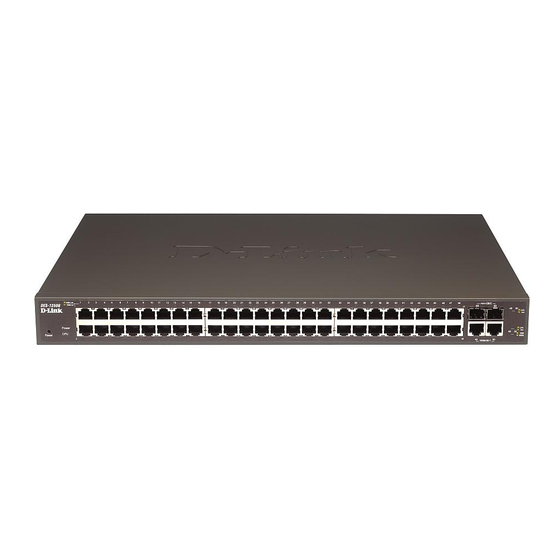
IDENTIFYING EXTERNAL COMPONENTS This chapter describes the front panel, rear panel, and LED indicators of the Switch. Front Panel The figure below shows the front panels of the Switch. Figure 3. Front panel of 48+2G-port Gigabit Ethernet Switch LED Indicator: Comprehensive LED indicators display the status of the Switch and the network (see the LED Indicators chapter below). -
Page 12: Understanding Led Indicators
UNDERSTANDING LED INDICATORS The front panel LEDs provide instant status feedback, and help monitor and troubleshoot when needed. Figure 5. LED indicators of the Switch Power and System LEDs POWER: Power Indicator : When the Power LED lights on, the Switch is receiving power. : When the Power turns off or the power cord has improper connection. -
Page 13: Ports 49~ 50 Mini-Gbic Status Leds
When the Amber light is on, the respective port is connected to a (Amber) 100Mbps Fast Ethernet network. : When the respective port is connected to a 10Mbps Ethernet or No link. Ports 49~ 50 mini-GBIC Status LEDs Link/ACT: Link/Activity : When the mini-GBIC transceiver is installed and connected to a network, the Link/ACT LED lights on. -
Page 14: Configuration
CONFIGURATION Through the Web Browser you can configure Switch settings such as VLAN, Trunking, QoS… etc. With the attached Web Management Utility, you can easily discover all Web Management Switches, assign the IP Address, change the password, and upgrade new firmware. Installing the Web Management Utility "If your utility is old version, please remove it and install v.1.01 or higher"... -
Page 15: Monitor List
Trap IP: Shows the IP where the Trap is to be sent. Subnet Mask: Shows the Subnet Mask set of the device. Gateway: Shows the Gateway set of the device. Monitor List All the Web Smart Devices in the Monitor List can be monitored; you can also receive traps and show the status of the device. System word definitions in the Monitor List: S: Shows the system symbol of the Web-Smart device, represents a device system that is not alive. -
Page 16: Toolbar
The factory default password is "admin." Figure 9. Configuration Setting Password Change: You can use this Password Change when you need to change the password, fill in the required passwords in the dialog box and press the “Set” button to process the password change immediately. Figure 10. -
Page 17: Configuring The Switch
In the “Option TAB”, there is the Refresh Time function; this function helps you to refresh the time for monitoring the device. Choose 15 secs, 30 secs, 1 min, 2 min, and 5 min to select the time for monitoring. In the “Help TAB”, there is About function, it will show out the version of the Web Management Utility. -
Page 18: Setup Menu
Figure 14. Device Status Setup Menu When the main page appears, find the Setup menu on the left side of the screen (Figure 15). Click on the setup item that you want to configure. There are eleven options: Port Settings, VLAN Settings, Trunk Setting, Device Status, Statistic, System Settings, Trap Setting, Password Setting, Backup Setting, and Reset Setting as shown in the Main Menu screen. -
Page 19: Vlan Settings (Virtual Local Area Network)
Figure 16. Port Configuration To change the port setting, click on the ID parameter to enter the selected port to configure its Speed/Disable, Flow control, and QoS setting. Figure 17. Speed: This setting has six modes—1000M Full, 100M Full, 100M Half, 10M Full, 10M Half, Auto, and Disable—for speed or port disable selections. Note: If the speed set to 100M full mode or 10M full mode, flow control should have the fixed setting set to disable. -
Page 20: Trunk Setting
VID group and press the “Remove the VID” button. To modify the VID group setting, select the VID group and change the setting, and press the “Apply” button to save the settings. Figure 18. When you select Port VLAN setting, fill in each port’s PVID value between 1 and 4094. Figure 19. -
Page 21: Device Status
Figure 1. Mirror setting Be sure that the selected trunk setting port connects to the device with a same VLAN group. Device Status Click on the “Status” button to present the device status on this screen, it will show the System Status, Port Status, VLAN Status, and Trunk Status. Press “Refresh”... -
Page 22: System Setting
System Setting The System Setting includes the System name, Location name, Login Timeout, IP Address, Subnet Mask, and Gateway. Through the Web Management Utility, you can easily recognize the device by using the System Name and the Location Name. The Login Timeout is used to set the idle time-out for security purposes. When there is no action while running the Web Smart Utility and the time is up, you must re-login to Web Smart Utility before you set the Utility. -
Page 23: Reset Setting
To restore a current setting file to the device, you must specify the backup file and press the “Restore” button to process the setting of the recorded file. Figure 28. Backup Setting Note: When restoring a recorded file, the current password will not be erased. Reset Setting The Factory Reset button helps you to reset the device back to the default setting from the factory. -
Page 24: Technical Specifications
TECHNICAL SPECIFICATIONS General Standards IEEE 802.3 10BASE-T Ethernet IEEE 802.3u 100BASE-TX Fast Ethernet IEEE 802.3z 1000BASE-SX/LX Gigabit Ethernet IEEE 802.3ab 1000BASE-T Gigabit Ethernet IEEE 802.3x Full Duplex Flow Control Protocol CSMA/CD Data Transfer Rate Ethernet: 10Mbps (half-duplex), 20Mbps (full-duplex) Fast Ethernet: 100Mbps (half duplex), 200Mbps (full-duplex) Gigabit Ethernet: 2000Mbps (full-duplex) Topology Star... - Page 25 The customer must submit with the product as part of the claim a written description of the Hardware defect or Software nonconformance in sufficient detail to allow D-Link to confirm the same, along with proof of purchase of the product (such as a copy of the dated purchase invoice for the product) if the product is not registered.
- Page 26 Warranty provides specific legal rights and you may also have other rights which vary from state to state. Trademarks: D-Link is a registered trademark of D-Link Systems, Inc. Other trademarks or registered trademarks are the property of their respective owners.
- Page 27 Product Registration Register online your D-Link product at http://support.dlink.com/register/ Product registration is entirely voluntary and failure to complete or return this form will not diminish your warranty rights.
-
Page 28: International Offices
Hsin-Tien, Taipei URL: www.dlink.dk URL: www.dlink.com.au Taiwan TEL: 886-2-2910-2626 Norway India FAX: 886-2-2910-1515 Karihaugveien 89 D-Link House, Kurla Bandra Complex Road URL: www.dlinktw.com.tw N-1086 Oslo Off CST Road, Santacruz (East) Norway Mumbai - 400098 Headquarters TEL: +47 99 300 100 India 2F, No.
Need help?
Do you have a question about the DES-1250G and is the answer not in the manual?
Questions and answers